Slash HPDC Porosity: A CFD-Based Guide to Optimizing Shot Sleeve Flow
This technical summary is based on the academic paper "Flow pattern analysis of melted aluminum in shot sleeve of pressure dies casting and minimizing the defect" by Rupesh Kumar Tiwari and Trilok Raj Chauhan, published in International Journal of Engineering Research and General Science (2015).
Keywords
- Primary Keyword: HPDC Porosity Reduction
- Secondary Keywords: Shot Sleeve Flow Analysis, Air Entrapment, Aluminum Die Casting, CFD Simulation, Plunger Velocity Control, Injection Chamber Optimization
Executive Summary
- The Challenge: High Pressure Die Casting (HPDC) of aluminum alloys is often plagued by gas porosity, a defect caused by air entrapment in the shot sleeve, which compromises the mechanical properties of the final component.
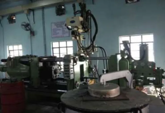
- The Method: The study utilized Computational Fluid Dynamics (CFD) simulation (GAMBIT and FLUENT) to analyze the flow behavior of molten aluminum in an HPDC injection chamber and validated the results with physical experiments on a 60-tonne HPDC machine.
- The Key Breakthrough: The research established a clear relationship between injection pressure and molten metal velocity, demonstrating that an optimum pressure range exists for a specific casting geometry to minimize turbulence and air entrapment.
- The Bottom Line: By optimizing plunger movement and injection pressure based on flow analysis, manufacturers can significantly reduce porosity defects, leading to higher quality, stronger, and more reliable die-cast parts.
The Challenge: Why This Research Matters for HPDC Professionals
In the competitive world of aluminum and magnesium alloy component production, defects are the enemy of profitability. One of the most persistent and challenging defects in High Pressure Die Casting (HPDC) is gas porosity. This issue arises when air is trapped within the molten metal in the shot sleeve during the high-speed injection phase. This entrapped air leads to voids in the final casting, severely degrading its density, tensile strength, and ductility.
For engineers and managers, this translates directly to increased scrap rates, costly post-processing, and potential field failures. While numerous strategies exist to combat porosity, finding the optimal injection parameters is a complex task. Eliminating one defect can often introduce another. This research was undertaken to move beyond trial-and-error by creating a reliable model to understand and control the root cause of air entrapment: the fluid dynamics within the injection chamber.
The Approach: Unpacking the Methodology
The researchers employed a dual approach, combining advanced simulation with real-world experimental validation to ensure the findings were both theoretically sound and industrially applicable.
Method 1: Computational Fluid Dynamics (CFD) Simulation
The core of the analysis was a CFD model designed to simulate the flow behavior of molten aluminum.
* Software: The team used GAMBIT for creating the 2D and 3D geometry and mesh of the shot sleeve and runner system. FLUENT, a state-of-the-art CFD software, was used to model the complex fluid flow and heat transfer dynamics.
* Model: The analysis was based on a shallow-water approximation model, which effectively captures wave profiles and reflections against the chamber's end wall—a critical factor in air entrapment.
* Variables Analyzed: The simulation investigated the impact of different inlet velocities (1 m/s, 3 m/s, 5 m/s) and injection pressures (40,000 kPa, 60,000 kPa, 80,000 kPa) on the flow pattern, pressure distribution, and vortex formation.
Method 2: Experimental Validation
To correlate the simulation with real-world conditions, the team conducted physical casting trials.
* Equipment: A 60-tonne cold chamber HPDC machine was used.
* Material: The experiments were performed using aluminum alloy.
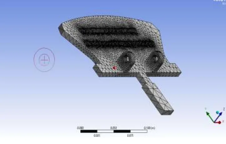
* Components Produced: Two distinct parts were manufactured: an "Engine cover" and an "automotive foot rest."
* Process Parameters: For the engine cover, an injection pressure of 80,000 kPa was required using a 40 mm diameter shot sleeve. For the footrests, 100,000 kPa was needed. These real-world parameters provided a baseline for validating the simulation's predictions.
The Breakthrough: Key Findings & Data
The combination of simulation and experimentation yielded critical insights into the relationship between injection parameters and fluid behavior, directly impacting defect formation.
Finding 1: Pressure and Velocity Have an Inverse Relationship
The study confirmed that as injection pressure increases, the velocity of the molten metal inside the chamber decreases. This aligns with Bernoulli's principle.
* When a pressure of 40,000 kPa was applied, the simulation showed high liquid aluminum velocity and significant, frequent pressure changes within the injection chamber, indicated by color variations in the pressure graph (Figure 24). This turbulence is a primary cause of air entrapment.
* When the pressure was increased to the actual operating level of 80,000 kPa (used for the engine cover), the velocity of the molten metal decreased. Crucially, the simulation showed that the large variations in pressure inside the chamber were reduced (Figure 28), leading to a more stable flow front and less opportunity for air to be folded into the melt.
Finding 2: An Optimum Pressure Range Exists for Defect Minimization
The research demonstrates that for any given casting and gating system geometry, there is an optimal pressure range, not just a minimum or maximum value.
* The analysis showed that while 40,000 kPa pressure resulted in a faster fill, it also created significant turbulence and vortex formation.
* The 80,000 kPa pressure, suitable for the engine cover model, resulted in a more controlled flow. The conclusion is that a fixed, optimized pressure range must be identified for each specific casting area to prevent both premature solidification and defect-inducing turbulence. This moves the process from "as fast as possible" to "as controlled as necessary."
Practical Implications for R&D and Operations
- For Process Engineers: This study suggests that adjusting the plunger acceleration and pressure profile is a powerful tool for minimizing air entrapment. Instead of simply increasing pressure to ensure fill, engineers should use CFD tools to identify the optimal pressure that balances fill time with flow stability to reduce porosity.
- For Quality Control Teams: The data in Figure 24 and Figure 28 of the paper illustrates the effect of injection pressure on flow stability. This connection can help QC teams trace porosity defects back to specific process parameter deviations during the injection phase, enabling more effective root cause analysis.
- For Design Engineers: The findings indicate that the geometry of the runner and gating system directly influences the pressure required and the resulting flow pattern. The paper notes that a smaller branch angle in the runner requires less pressure and reduces resistance, which is a valuable consideration in the early die design phase to promote stable flow.
Paper Details
Flow pattern analysis of melted aluminum in shot sleeve of pressure dies casting and minimizing the defect
1. Overview:
- Title: Flow pattern analysis of melted aluminum in shot sleeve of pressure dies casting and minimizing the defect
- Author: Rupesh Kumar Tiwari, Trilok Raj Chauhan
- Year of publication: 2015
- Journal/academic society of publication: International Journal of Engineering Research and General Science Volume 3, Issue 4, Part-2, July-August, 2015
- Keywords: CFD, Fluent, Gambit, Simulation, HPDC machine etc.
2. Abstract:
Cold chamber high pressure die casting, (HPDC), is a vital business process for the production of complex near net shape aluminum and magnesium alloy castings. The investigations were carried out mainly using the aluminum alloy. High Pressure Die Casting (HPDC) is a complex process that results in casting defects if organized inappropriately. Though, finding out the optimum construct is a quite uphill task as eliminating one of the casting defects (for example, porosity) can result in occurrence of other casting defects. The purpose of the project is to improve current modeling and understanding of defects formation in HPDC machines. An attempt has been made to analysis the flow behavior of metal (Aluminum) in HPDC injection chamber. The flow in the injection chamber of pressure die casting machines is analyzed using a model based on the shallow-water approximation which takes into account the effects of wave reflection against the end wall of the chamber. The results of the model for wave profiles, volume of air remaining in the injection chamber at the instant at which the molten metal reaches the gate to the die cavity, and optimum values of the parameters characterizing the law of plunger motion are observed to reduce the porosity defect. We found that, although the shallow water model does not provide a very accurate estimation of the mass of entrapped air in the injection chamber for certain ranges of working conditions, it does describe reasonably well the influence of the acceleration parameters and the initial filling fraction on the entrapped air mass, and can be of help in selecting operating conditions that reduce air entrapment while keeping the injection chamber filling time as low as possible.
3. Introduction:
Many research efforts have been conducted in areas such as technology and material development to improve the pressure die casting process. The HPDC process is now widely applied, leading researchers to focus on its use for casting complex shapes and lightweight components. The introduction reviews previous studies on related topics, including simulation of molten metal flow, the effect of vacuum assistance on reducing gas porosity, partial squeeze casting, and optimizing plunger acceleration to diminish air entrapment. These prior works establish the context and significance of analyzing flow patterns to control defects in HPDC.
4. Summary of the study:
Background of the research topic:
HPDC is a critical manufacturing process for complex aluminum and magnesium parts, but it is susceptible to defects like porosity if not properly controlled. Porosity is often caused by the entrapment of air in the molten metal during the high-speed injection phase within the shot sleeve.
Status of previous research:
Previous research has explored various aspects of HPDC, including: simulation of flow in runner systems (Sulaiman, et al., 1997), the benefits of vacuum assistance to reduce porosity (Niu et al., 1999), partial squeeze and vacuum processes (Lee et al., 2000), and optimizing plunger acceleration in the slow shot phase (Lopez et al., 2001). These studies highlight an ongoing effort to understand and control the factors leading to defects.
Purpose of the study:
The purpose of this project is to improve the modeling and understanding of defect formation in HPDC. Specifically, it aims to analyze the flow behavior of molten aluminum in the HPDC injection chamber to identify operating conditions that reduce air entrapment and porosity while maintaining a low filling time.
Core study:
The core of the study involves using a CFD model based on a shallow-water approximation to analyze the flow in the injection chamber. The model evaluates wave profiles, the volume of remaining air, and the effect of plunger motion parameters. These simulation results are then correlated with physical experiments conducted on an HPDC machine producing aluminum parts (an engine cover and footrests) under varying pressure conditions. The study analyzes the relationship between applied pressure, molten metal velocity, and flow stability to determine an optimal process window for minimizing defects.
5. Research Methodology
Research Design:
The study utilized a combined simulation and experimental research design. A computational model was first developed to simulate the fluid dynamics inside the HPDC shot sleeve. The findings from the simulation were then validated and correlated with data from physical casting trials performed on an industrial HPDC machine.
Data Collection and Analysis Methods:
- Simulation: The geometry and mesh for the shot sleeve were created using GAMBIT. The fluid flow analysis was performed using FLUENT CFD software. The simulation analyzed flow patterns, pressure contours, and velocity vectors at different inlet velocities (1, 3, 5 m/s) and pressures (40000, 60000, 80000 kPa).
- Experimentation: A 60-tonne HPDC machine was used to cast aluminum parts. Process parameters such as injection pressure (80000 kPa for engine cover) and shot sleeve diameter (40 mm) were recorded. The physical results served as a basis for validating the simulation's predictions about flow behavior under industrial conditions.
Research Topics and Scope:
The research focuses on the flow pattern of molten aluminum within the shot sleeve of a cold chamber HPDC machine. The scope includes analyzing the effects of plunger motion and injection pressure on air entrapment and porosity. The study aims to identify an optimum operating pressure range for a specific casting geometry to minimize defects.
6. Key Results:
Key Results:
- An inverse relationship between applied injection pressure and the velocity of molten metal was observed, consistent with Bernoulli's principle.
- At a lower pressure of 40,000 kPa, the molten metal velocity was high, but the flow was turbulent with significant pressure variations, increasing the risk of air entrapment.
- At a higher, optimized pressure of 80,000 kPa, the metal velocity was lower, but the flow was more stable with reduced pressure fluctuations, leading to less turbulence and a lower probability of vortex formation.
- The study concludes that for a specific casting geometry, a fixed, optimal range of pressure exists that minimizes defects by balancing the need for complete die filling with the need for a stable, non-turbulent flow front.
Figure Name List:
- Fig 1. Basic fluent structure
- Fig 2 Types of grid
- Fig 3. Grid shape in simple and complex geometry
- Fig 4. Domain type
- Fig 5. Boundary condition and velocity inlet window
- Fig 6. Grid formation in domain
- Fig 7. HPDC Machine
- Fig 8. Engine cover and footrests
- Fig 9. Grid size details
- Fig 10. Pressure plot at velocity 1m/s
- Fig 11. Velocity plot to 1m/s
- Fig 12. Zoom to runner
- Fig 13. Stream function plot
- Fig 14. Pressure plot 3 m/s
- Fig 15. Velocity plot at 3 m/s
- Fig 16. Velocity plot (zoom to runner)
- Fig 17. Stream function plot
- Fig 18. Flow behavior at 5 m/s
- Fig 19. Velocity plot
- Fig 20. Zoom to runner
- Fig 21. Stream function plot
- Fig 22. Model of engine cover
- Fig 23. Fully meshed model
- Fig 24. Pressure graph when the pressure is 40000 Kpa
- Fig 25. Velocity plot
- Fig 26. Pressure based plot at 60000 Kpa
- Fig 27. Velocity plot
- Fig 28. Pressure based plot
- Fig 29. Velocity plot
- Fig 30. 3d model of footrest
- Fig 31. Meshing of structure
- Fig 32. Contour of Residual
- Fig 33. Solidification of casting
- Fig 33. Plot between pressure and velocity
7. Conclusion:
An analysis of the flow behavior of molten aluminum in an HPDC injection chamber was conducted. The study observed the formation of vortexes due to pressure variations using CFD simulations with GAMBIT and FLUENT. Simulations with different plunger speeds and movements demonstrated the importance of correct plunger profiles. The results show that for every change in pressure, there is a corresponding change in the flow behavior of the liquid aluminum. This leads to the conclusion that for a specific size of injection chamber, there is an optimum value of pressure that minimizes defects. Future work will involve improving casting quality by minimizing entrapped air and optimizing the entire process by controlling filling with optimal plunger movement.
8. References:
- [1] Sulaiman, Shamsuddin, and Tham Chee Keen. "Flow analysis along the runner and gating system of a casting process." Journal of materials processing technology 63.1 (1997): 690-695.
- [2] Niu, X. P., et al. "Vacuum assisted high pressure die casting of aluminium alloys." Journal of Materials Processing Technology 105.1 (2000): 119-127.
- [3] Kim, E. S., K. H. Lee, and Y. H. Moon. "A feasibility study of the partial squeeze and vacuum die casting process." Journal of Materials Processing Technology 105.1 (2000): 42-48.
- [4] Faura, F., J. Lopez, and J. Hernandez. "On the optimum plunger acceleration law in the slow shot phase of pressure die casting machines." International Journal of Machine Tools and Manufacture 41.2 (2001): 173-191. Thompson, Joe F. "Grid generation techniques in computational fluid dynamics." AIAA journal 22.11 (1984): 1505-1523.
- [5] Mao, Haijing. A numerical study of externally solidified products in the cold chamber die casting process. Diss. The Ohio State University, 2004.
- [6] Kallien, Lothar H. "Using Gas Injection in High Pressure Die Casting Technology." 113th Metalcasting Congress, Las Vegas, Nevada. (2009).
- [7] Sahu, M., et al. "Developed laminar flow in pipe using computational fluid dynamics." 7th International R &D Conference on Development and Management of Water and Energy Resources, 4-6 February 2009, Bhubaneswar, India. 2009.
- [8] Kuriyama, Y., K. Yano, and S. Nishido. "Optimization of Pouring Velocity for Aluminium Gravity Casting." Fluid Dynamics, Computational Modeling and Applications (2012).
- [9] Sirviö, M. and Martikainen, H. “Simultaneous engineering between workshops and foundries”. Int. Conf. on Best Practices in the Production, Processing and Thermal Treatment of Castings. Singapore,
- [10] Kuo, T.-H., and Hwang, W.-S., 1998, "Flow Pattern Simulation in Shot Sleeve During Injection of Diecasting,” AFS Transactions, Vol. 106, pp. 497-503.
- [11] www.castool.com/sites/default/files/publications/vacuum_assisted_die_casting_todays_most_significant_technology_print.pdf, Paul Robbin: 2012.
- [12] Brevick, J. R., Armentrout, D. J., and Chu, Y., 1994, “Minimization of Entrained Gas Porosity in Aluminum Horizontal Cold Chamber Die Casting,” Transactions of NAMRI/SME, Vol. 22, pp. 41-46.
- [13] Duran, M., Karni, Y., Brevick, J., Chu, Y., and Altan, T., 1991, “Minimization of Air Entrapment in the Shot Sleeve of a Die Casting Machine to Reduce Porosity,” Technical Report ERC/NSM-C-91-31, The Ohio St ate University.
- [14] Thome, M. C., and Brevick, J. R., 1993, "Modeling Fluid Flow in Horizontal Cold Chamber Die Casting Shot Sleeves,” AFS Transactions, Vol. 101, pp. 343-348.
- [15] Sekhar, J. A., G. J. Abbaschian, and R. Mehrabian. "Effect of pressure on metal-die heat transfer coefficient during solidification." Materials Science and Engineering 40.1 (1979): 105-110, 10 - 12 Oct. 1995. Paper 17-1-6
Expert Q&A: Your Top Questions Answered
Q1: Why did the researchers use a "shallow-water approximation" for their model?
A1: The abstract states the shallow-water approximation was used because it effectively takes into account the effects of wave reflection against the end wall of the injection chamber. This wave action is a primary mechanism for folding air into the molten metal. While the model may not be perfectly accurate for estimating the total mass of entrapped air, it is very effective for understanding the influence of acceleration and fill fraction on air entrapment, making it a valuable tool for selecting better operating conditions.
Q2: What specific software tools were central to this study's simulation work?
A2: The study relied on two key pieces of software. GAMBIT was used as the pre-processor to generate the 2D and 3D geometry of the shot sleeve and create the computational mesh. The core fluid flow simulation and analysis were then performed using FLUENT, a powerful and widely-used commercial CFD program for modeling fluid flow and heat transfer.
Q3: The paper says higher pressure leads to lower velocity. Isn't that counterintuitive?
A3: While it might seem so, this finding is consistent with Bernoulli's principle for fluid dynamics. The applied pressure is a form of potential energy. As the fluid is forced through the system, this potential energy is converted into kinetic energy (velocity). However, the simulation shows that the stability of the flow front is a more critical factor for preventing air entrapment than raw speed. The higher pressure (80,000 kPa) created a more controlled, less turbulent flow, which is ultimately better for reducing porosity.
Q4: What was the key takeaway from the experimental validation using the engine cover part?
A4: The experiment with the engine cover, which required 80,000 kPa of pressure, served as a crucial real-world data point. The simulations confirmed that at this specific pressure, the pressure fluctuations inside the shot sleeve were minimized compared to lower pressures. This correlation between the simulation and a successful physical casting process validates the model's conclusion: there is an optimal pressure for a given part that minimizes defect-causing turbulence.
Q5: How can a die casting facility apply these findings without running complex CFD simulations for every part?
A5: The core principle is that plunger speed and pressure profiles must be optimized for flow stability, not just for fill speed. Even without a full simulation, process engineers can apply this knowledge by methodically testing and documenting the effects of incremental changes to the slow and fast shot profiles. The study reinforces that a "one size fits all" injection profile is suboptimal; profiles should be tailored to the part geometry to achieve a stable flow front, which can be observed through short-shot analysis and final part quality inspection.
Conclusion: Paving the Way for Higher Quality and Productivity
The persistent challenge of gas porosity in aluminum die casting directly impacts production costs and component reliability. This research provides a clear, actionable framework for tackling the problem at its source. By moving beyond a simple "faster is better" approach to injection, the study demonstrates that optimizing pressure for flow stability is the key to HPDC Porosity Reduction. The breakthrough finding—that an optimal pressure range exists to minimize turbulence and air entrapment—empowers engineers to make more informed decisions about process parameters.
At CASTMAN, we are committed to applying the latest industry research to help our customers achieve higher productivity and quality. If the challenges discussed in this paper align with your operational goals, contact our engineering team to explore how these principles can be implemented in your components.
Copyright Information
This content is a summary and analysis based on the paper "Flow pattern analysis of melted aluminum in shot sleeve of pressure dies casting and minimizing the defect" by "Rupesh Kumar Tiwari, Trilok Raj Chauhan".
Source: https://www.ijergs.org/files/documents/Flow-11.pdf
This material is for informational purposes only. Unauthorized commercial use is prohibited.
Copyright © 2025 CASTMAN. All rights reserved.