by Daliang Yu 1,Wen Yang 2,Wanqing Deng 2,Songzhu Zhu 2,Qingwei Dai 1,3,* andDingfei Zhang 31School of Metallurgy and Materials Engineering, Chongqing University of Science and Technology, Chongqing 401331, China2Chongqing Zhicheng Machinery Co., LTD, Chongqing 400039, China3College of Materials Science and Engineering, Chongqing University, Chongqing 400045, China*Author to whom correspondence should be addressed.Metals2021, 11(1), 97; https://doi.org/10.3390/met11010097Received: 27 November 2020 / Revised: 25 December 2020 / Accepted: 1 January 2021 / Published: 6 January 2021
Abstract
Hot tears were frequently formed in Aluminum (Al) parts with complex structure. In this study, OM (optical microscope), SEM (scanning electron microscope), EDS (energy dispersive spectrometer), and FDM (finite difference method) were used to reveal the hot tears mechanisms in the casted AC4B Al engine. Shrinkage porosities with the size of 300–500 μm were found in casted specimens near the parts’ surface. Many cracked brittle Fe-bearing phase were also found in crack section. The secondary dendrite arm spacing observation in five typical positions showed that the cooling rate in position 5 was faster than that in position 1. The impropriety solidification sequence in position 5 and position 1 impeded the solidification feeding of position 1, and it might lead to casting defects or even casting cracks. Numerical simulation also showed that solidification sequence promoted casting defects, which was accordant with microstructure observation. Impurity may concentrate at position 5 during filling. It is concluded that large β-Fe intermetallics and improper solidification sequence together contributed to crack initiation in the engine.
Keywords: aluminum alloy; casting defects; casting sequence; microstructure
Korea
복잡한 구조를 가진 알루미늄 (Al) 부품에서 뜨거운 눈물이 자주 형성되었습니다. 이 연구에서는 OM (광학 현미경), SEM (주사 전자 현미경), EDS (에너지 분산 분광계) 및 FDM (유한 차이 방법)을 사용하여 주조 된 AC4B Al 엔진의 뜨거운 눈물 메커니즘을 밝혀 냈습니다. 300–500 μm 크기의 수축 다공성은 부품 표면 근처의 주조된 시편에서 발견되었습니다. 균열 부에서 많은 균열이 있는 취성 철 함유 상도 발견되었다.
5 개의 일반적인 위치에서 2 차 수상 돌기 암 간격 관찰은 위치 5의 냉각 속도가 위치 1의 냉각 속도보다 빠르다는 것을 보여주었습니다. 위치 5와 위치 1의 부적절한 응고 시퀀스는 위치 1의 응고 공급을 방해하고 캐스팅으로 이어질 수 있습니다. 결함 또는 주조 균열. 수치 시뮬레이션은 또한 응고 순서가 미세 구조 관찰과 일치하는 주조 결함을 촉진한다는 것을 보여주었습니다. 충전 중에 불순물이 위치 5에 집중 될 수 있습니다. 큰 β-Fe 금속 간 화합물과 부적절한 응고 순서가 함께 엔진의 균열 발생에 기여한 것으로 결론지었습니다.
1. Introduction
In an effort to improve vehicle fuel efficiency, Al alloys have been increasingly used as engineering components in the automotive industry [1,2]. Al-Si-Cu series cast alloys were widely used as engine and engine blocks in the automotive industry for its good castability and excellent mechanical properties in ambient and elevated temperature [3,4]. The service performance of cast Al alloys components can be affected by many factors, such as alloying elements, casting methods, technological parameters, and so on [5,6,7]. Casting defects, such as hot tearing, embrittling secondary phases, porosity, and solidification shrinkage frequently cause performance deterioration in applications [8].AC4B alloys is a typical Al-Si-Cu series cast Al alloy that has been used in engines for decades. When using as engine parts, AC4B alloys were usually manufactured by low pressure casting for their good formability, high corrosion resistance, and good comprehensive mechanical properties. The solidification of AC4B alloys occurs in a temperature range. The certain solidification ranges were influenced by compositions, processing parameters and so on. As the result, the occurrence of casting defects are sensitive to thermal gradients, solidification shrinkage, and filling flow [6,9,10]. Generally, a fast cooling rate leads to fine grain size and decreased dendrite spacing; the fine microstructure is a benefit to mechanical properties [11]. When the dendrite spacing become finer, the liquid films between grains will also become more homogenous and thinner, which can result in higher strength and ductility [12]. Casting defects have a great influence on material properties and product quality. The prominent casting defects in components would lead to premature failure in service [13,14]. To obtain a higher functional performance of an engine, some engine structure was quite complex. However, the complex structural design changed the heat dissipation and filling flow of components, which bring a great challenge in engine manufacturing. The same casting parameters may lead to a different microstructure and casting defects in different engines. Microstructure and casting defects have a great influence on service performance; thus, the casting parameters should be modified in different engineering components.The newly designed casted Al engine has a specific complex structure, and hot cracks were frequently found in these engines in the same position. Studying hot cracks initiation mechanisms in these casted engines can not only improve products’ quality but also give us a further understanding of the relationship between components’ structure and casting defects.In this study, the microstructure in five typical positions of engines were observed to reveal the microstructure variation during the casting process. Crack surface was also observed to study the crack initiation during manufacturing process. Numerical modeling methods were used to study temperature field and solidification sequence in casting. The microstructure and solidification sequence of cast alloys was discussed to evaluate the relationship of microstructure and crack initiation mechanisms.
2. Experiments
The materials used in this study were AC4B Al alloys. The chemical compositions of the alloys were measured by the optical emission spectrometer (SPECTRO, Kleve, Germany). The results were 9.26 wt.% Si, 2.89 wt.% Cu, 0.65 wt.% Mg, 0.78 wt.% Zn, 0.86 wt.% Fe, 0.12 wt.% Mn, and the balance Al. The Al alloy were melted at 800 °C, and the melt was stirred by high purity nitrogen. When the melt passed the chemical composition tests, the melt was transferred to a maintaining furnace (Sinfor Equipment, Foshan, China) and kept at the temperature range of 700–900 °C for refinement and degasification. Some hexachloroethane degasser (Nuoyu Chenistry, Jinan, China) was added to the melt and kept aerating with high purity nitrogen for 9–12 min; the rotate speed was 500–600 r/min. When the Al melt passed the final chemical composition tests, the melt were left to set for 10 min. Then the Al melt were casted by low pressure die casting. The casted engines were successively processed by decore, solution treatment, quenching, and aging treatment. Solution treatment was conducted at 490 °C for 4 h. After solution treatment, the engines were quenched to hot water with temperature of 70 °C within 20 s. Aging treatment was conducted at 240 °C for 4 h. The casted, quenched and aging treated specimens were chosen for microstructure observation. These specimens were cut into two parts, microstructure observation was carried out on the cross section in different positions. Scanning electron microscope (SEM) and optical microscope were used for microstructure observation. The equipment for microstructure observation are ZEISS GeminiSEM 300 field emission scanning electron microscopy (Oberkochen, Germany) and Leica DM2500 optical microscope (Wetzlar, Germany). The specimens and positions that were selected for microstructure are illustrated in Figure 1. Five typical positions were chosen. Position 3 is in the button of the engine and position 4 is in the top of the engine. The casted, quenched, and aged engine were tested by eddy current inspection. If macro cracks were detected, then the crack area were cut off and specimens were broken into two parts along cracks for crack surface observation.
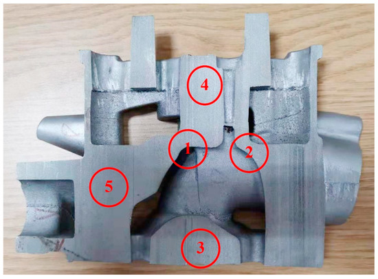
Figure 1. Sketches of selected specimens for microstructure observation.Numerical simulation of solidification and filling flow were carried out by Any Casting to help study the distribution of inclusions and gas in the casting process. The casting temperature is 700 °C, the temperature of the bottom die and upper die were 450 °C and ~300 °C, and the temperature of the side die and sand cores were ~370 °C and 25 °C. The material parameter of AC4B alloy is listed in Table 1.Table 1. Material parameter of AC4B alloy.
Table 1. Material parameter of AC4B alloy.
| Materials | Density kg/m3 | Specific Heat J/kg·k | Heat Conductivity W/m·k | Liquidus Temperature °C | Solidus Temperature °C | Shrinkage of Volume % |
|---|---|---|---|---|---|---|
| AC4B | 2770 | 963 | 96 | 590 | 520 | 7.14 |
3. Results
3.1. Optical Microstructure
Figure 2 shows optical microscope (OM) microstructure of casted and quenched specimens in position 1, position 3, and position 4, respectively. Since hot cracks were frequently found in position 1, and position 3, position 4 were at the bottom and at the top of the engine, Position 1, position 3, and position 4 were chosen as three typical positions. The secondary dendrite spacing of casted specimens in position 1, position 3, and position 4 were ~43 μm, ~48 μm, and ~20 μm, respectively. The secondary dendrite spacing of quenched specimens in position 1, position 3, and position 4 were ~44 μm, ~47 μm, and ~21 μm, respectively. Position 4 showed much finer microstructure than that in position 1 and position 3. It can also be found that solution treatment and quenching treatment almost has no effect on secondary dendrite spacing.
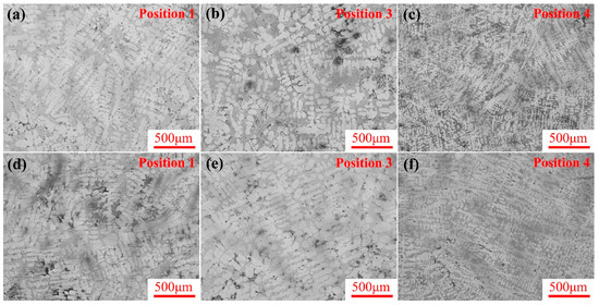
Figure 2. Optical microstructure of casted specimens in different positions: (a) position 1, (b) position 3, (c) position 4. Optical microstructure of quenched specimens in different positions: (d) position 1, (e) position 3, (f) position 4.
3.2. Typical Casting Defects
SEM was used to observe the casted microstructure. Five typical positions (position 1 to 5, as illustrated in Figure 1) were chosen for SEM observation. Casting defects were mainly found in position 1 and position 3. Figure 3 shows the typical casting defects in components. Casting defects in position 1 are shown in Figure 3a–c, and casting defects in position 3 are shown Figure 3d.
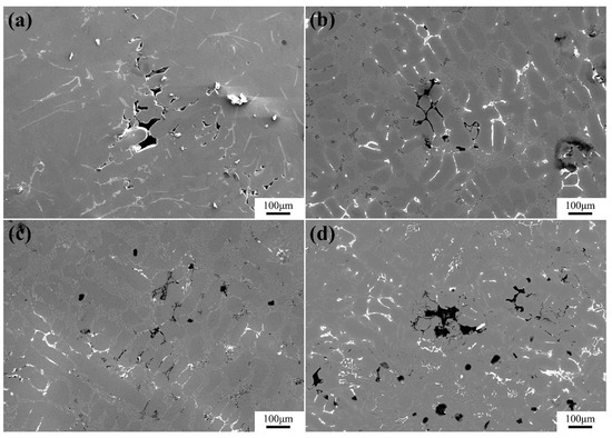
Figure 3. Typical casting defects (a–c) in position 1 and (d) in position 3.Figure 3a–c shows typical casting defects of position 1. The backscattered electron images showed that oxide was not prominent around these casting defects. It can be concluded that the casting defects in position 1 were mainly shrinkage porosities. The casting defects in position 1 were mainly caused by solidification feeding. Position 3 also had many casting defects; the morphology of observed casting defects in position 3 was slight different from that in position 1. The dark contrast in casting defects of position 3 indicated that many oxide embedded in position 3. These oxide in position 3 means the casting defects may result from inclusions and gas.
3.3. Crack Surface
Based on specimens’ inspection, macro cracks can only be found in position 1. The specimens that have macro cracks were cut into two parts along the crack and then were observed by SEM. The crack surfaces of casted specimens are shown in Figure 4. As shown in Figure 4, there were two kinds of defects that could be seen in casted specimens. Casting flaws are shown in Figure 4a,b. Cracked big intermetallics are shown in Figure 4b–d. The size of the casting flaw is 300–500 μm, and these casting defects could only be found near the surface of specimens. While the distribution of big intermetallics was more random, big intermetallics with the size of ~300 μm embed in position 1 even far away from the specimens’ surface. The cracked big intermetallics with many cleavage-liked features, and the fracture surface of big intermetallics is more flat than matrix.
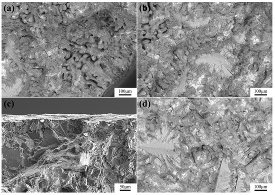
Figure 4. The crack surface of casted specimens, typical casting flaws in position 1 (a,b), typical cracked intermetallics in position 1 (c,d).Energy dispersive spectrometer (EDS) map scanning was carried out on casting flaw areas in casted specimens, as shown in Figure 5. Inclusions and shrinkage porosities were two typical casting defects. The presence of inclusions often accompanied by lots of oxide, shrinkage porosities were always resulted from un-directional solidification and insufficient feeding of melt [15]. As a consequence, shrinkage porosities were always cavities and didn’t contain oxygen [16]. As can be seen in Figure 5, oxygen cannot be found in casting flaw areas. It means that the casting flaws in position 1 are shrinkage porosities [17].
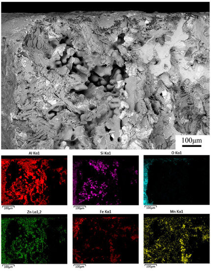
Figure 5. The results of energy dispersive spectrometer (EDS) map scanning in casting flaw.
3.4. Typical Intermetallics
EDS was used to study the chemical composition of bulk intermetallics on crack surface. Figure 6 shows the EDS map scanning results of intermetallics on crack surface in casted specimens. It can be seen that the crack surface of big intermetallics was more flat than other areas, the size of big intermetallics was about ~300 μm. The EDS map scanning results showed that the big intermetallics were mainly constituted by Fe and Mn element. Since the specimens were new-made, little oxygen element can be found on crack surface. As reported, there are two typical Fe-bearing intermetallics in AC4B alloy, one containing primary α-Fe intermetallics, and the other containing plate-shaped β-Fe [18,19]. The morphologies of Fe-bearing intermetallics are plate-shaped, polyhedral/compact or Chinese script. The size and morphology of Fe-bearing intermetallics were mainly determined by thermal history and chemical composition [6,20]. The primary phase were formed during solidification. It can be concluded that the formation of these big compound were related to casting technique.
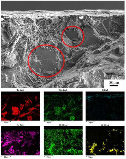
Figure 6. The results of EDS map scanning of intermetallics on fracture surface in casted specimens.Figure 7 shows the results of EDS point scanning in intermetallics of casted specimens and the elementary composition of four typical points. It can be seen that content of Fe and Mn element in point A and point B were much higher than matrix (point C), especially in point A. The big Fe-bearing intermetallics were feather-like or plate-shaped with high content of Fe element. These plate-shaped Fe-bearing intermetallics in this work were β-AlxFeySiz [13,21]. As reported, the Fe-bearing intermetallics play an important role in crack initiation. The plate-shaped β-Fe was the most detrimental intermetallic in crack initiation and weakened the mechanical properties [15,22,23,24]. The plate-shaped β-Fe particles impeded the liquid films’ free flow within the semi-solid structure. As the result, the casting feed was not sufficient.
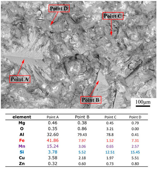
Figure 7. The results of EDS point scanning of big compound in casted specimens.The crack surface backscattered electron images of aged specimens were shown in Figure 8. As can be seen from Figure 8, big intermetallics could also be found in aged specimens, some cracks embed in this compound. The morphology of intermetallics in aged specimens was quite different from the Fe-bearing phase in casted specimens. EDS point scanning was carried out on the aged specimens, and the results are shown in Figure 8. Form the results of EDS, it could be found that the big compound in aged specimens were mostly the Cu-bearing phase. Some Fe-bearing phase can also be found in aged specimens (point D). The Fe-bearing phase were not dominant in aged specimens, since aged specimens were subjected to solution treatment and aging treatment. The Fe-bearing phase dissolved into the matrix during solution treatment and led to the reduction of Fe-bearing phase in aged specimens [25,26]. Some bulk Cu-bearing phase can be found in aged specimens. In aging treatment, the Cu-bearing phase precipitated from supersaturated solid solution and resulted in the formation of these new phase. EDS results confirmed that these precipitated phases were mainly formed in aging treatment.
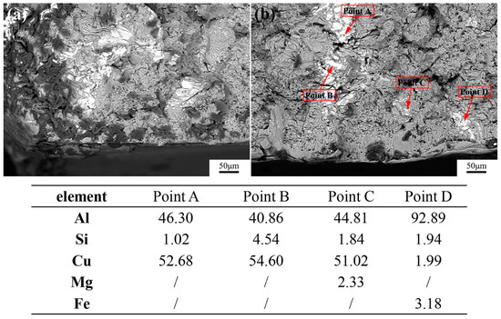
Figure 8. Typical crack surface of aged specimens.
3.5. Secondary Dendrite Spacing
The component structure has a great influence on the solidification process [8,14]. Inappropriate solidification sequence may lead to crack initiation during casting. Since the engine has a complex structure, optical microstructure of casted specimens in five typical positions (position 1 to 5, as illustrated in Figure 1) were observed. The secondary arm spacing was measured by Image J software based on optical micrographs. To verify the relationship between secondary arm spacing and casting crack, both eligible engine and rejected engine were chosen for optical microstructure observation.Figure 9 showed the optical microstructure of eligible specimens in five positions. It can be found that all five positions showed typical cast microstructure with dendrite, and bulk compound was also found between dendrite. Dendritic spacing in five positions were markedly different. The dendrite in position 4 is much finer than the other four positions. The growth of dendrite is closely related to the cooling rate in the casting process.
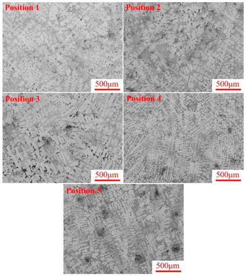
Figure 9. Optical microstructure in different positions of eligible specimens.The optical microstructure of rejected specimens in different positions were shown in Figure 10. Position 4 also showed the finest dendrite in rejected specimens. In comparison of the optical microstructure, there were no obvious differences between eligible specimens and rejected specimens. The dendritic structure observed by OM in position 4 is much finer than other positions that was in accordance with OM microstructures in Figure 2.
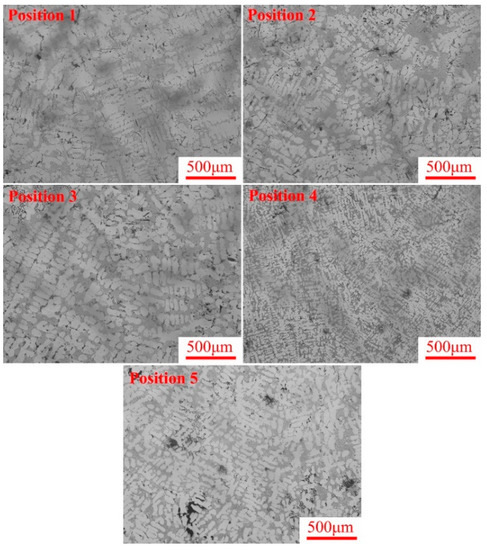
Figure 10. Optical microstructure in different positions of rejected specimens.
4. Discussion
4.1. Distribution of Temperature Field
In casting process, temperature field has a great influence on microstructure and mechanical properties. Numerical simulation was used to reveal the temperature variation and solidification sequence [27].Figure 11 shows the numerical simulation of filling process. As can be seen in Figure 11a, aluminum metal level converged at position 1 (schematic in blue wireframe). In the filling process, the melt flow together often promote casting defects such as air entrapment and inclusions. In Figure 11b, we found that the temperature in position 1 (blue wireframe) was slightly higher during filling. The high casting temperature gave rise to coarse microstructure. The characteristics of filling flow and temperature field in the casting process demonstrated that more casting defects and coarse microstructure indeed tend to generate in position 1 [28,29].
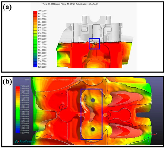
Figure 11. Filling flow numerical simulation (a) front view of the engine, (b) top view of the engine.Since casting flows mainly emerged in position 1, position 1 was emphasized in numerical simulation. The numerical simulation in solidification process was shown in Figure 12. It can be found that the cylinder head was not solidified from component top to the bottom in sequence. Position 5 solidified before position 1. If position 5 solidified before position 1, the path for solidification feeding would be interrupted, as the consequence solidification feeding in position 1 was hindered. The insufficient solidification feeding promoted casting defects in position 1.
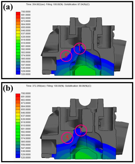
Figure 12. Numerical simulation of solidification process (a) front view of the engine at solidification rate about 67%, (b) front view of the engine at solidification rate about 68%.
4.2. Solidification Sequence
The optical microstructure in different positions were shown in Figure 9 and Figure 10; in these figures it could be found that microstructure were quite different in dependence on positions. The secondary arm spacing and solidification sequence of eligible specimens were shown in Table 2. In order to obtain precise secondary arm spacing, hundreds of secondary dendrite were measured for each position. It can be seen that the specimens in different positions had different secondary arm spacing.Table 2. Secondary arm spacing and solidification sequence of eligible specimens.
Table 2. Secondary arm spacing and solidification sequence of eligible specimens.
| Position | Statistical Magnitude | Secondary Arm Spacing | Solidification Sequence |
|---|---|---|---|
| 1 | 322 | 42.9 | 4 5 2 1 3 |
| 2 | 461 | 41.2 | |
| 3 | 535 | 48.8 | |
| 4 | 618 | 18.7 | |
| 5 | 630 | 40.6 |
In casting process, the secondary arm spacing and cooling rate can be expressed qualitatively as the following equation:1d∝dTdt=T0−Ttdtwhere d is the secondary arm spacing, T0 is casting temperature, Tt is solidification temperature [30,31]. From this equation, we can conclude that fast cooling rate can result in fine dendrite. The coarse dendrite in the engine is mainly due to improper cooling rate.In this engine, the chemical composition of the five positions were almost the same, thus the difference of secondary arm spacing is resulted from the cooling rate. Position 4 has the finest secondary arm spacing with the size of 18.7 μm, whereas the secondary arm spacing of position 3 is 48.8 μm, which is more than two times of position 4. The engine was casted at 700 °C, and the variation of the secondary arm spacing in different positions means that the component’s structure indeed has great influence on the solidification process. During the casting process, the high cooling rate results in a low secondary dendrite arm spacing and more excellent mechanical properties of the Al components [32]. As shown in Figure 1, position 4 is on the top of the engine while position 3 is on the bottom. The cooling rate in position 4 is much faster than that in position 3; the fast cooling rate could lead to fine casted microstructure. Therefore, the magnitude of secondary arm spacing can reflect the solidification sequence. Based on secondary arm spacing, the solidification in sequence of eligible specimens was position 4, position 5, position 2, position 1, and position 3.The secondary arm spacing and solidification sequence of rejected specimens were shown in Table 3. Although the optical microstructure of eligible specimens and rejected specimens were almost the same, it’s interesting to find that the secondary arm spacing of rejected specimens was slightly coarser than that of the eligible specimen (except position 2). Based on secondary arm spacing, the solidification in sequence of rejected specimens was position 4, position 2, position 5, position 1, and position 3.Table 3. Secondary arm spacing and solidification sequence of rejected specimens.
Table 3. Secondary arm spacing and solidification sequence of rejected specimens.
| Position | Statistical Magnitude | Secondary Arm Spacing | Solidification Sequence |
|---|---|---|---|
| 1 | 795 | 48.8 | 4 2 5 1 3 |
| 2 | 504 | 39.8 | |
| 3 | 413 | 52.2 | |
| 4 | 308 | 22.2 | |
| 5 | 830 | 42.2 |
During the casting process, the coarser casted microstructure was frequently related to casting defects and resulted in deteriorated mechanical performance [33]. From Table 2 and Table 3, it could be found that in the casting process, position 5 solidified before position 1 in both eligible and rejected specimens. The engine was casted by low pressure casting, solidification feeding rely on melt in the lower part. If position 5 solidified before position 1, the solidification feeding of position 1 would be impeded, and it may lead to casting defects or even casting cracks.As discussed above, the cooling rate and solidification sequence has a great influence on casting quality. Since the engine had a complex structure, the cooling rate was various in different positions that result in the unpredictable solidification sequence; impertinent solidification sequence could lead to casting defects [34].
4.3. Crack Initiation Mechanisms
Casting defects and intermetallics are two main factors that promote crack initiation in light alloys [5,20,35]. During the casting process in AC4B alloy, casting defects were closely related with casting techniques especially cooling rate. As discussed above, since the engine had a complex structure, the unexpected solidification sequence resulted in casting defects. What was worse, these casting defects might promote crack initiation. In casting Al alloys, the plate-shaped β-Fe (β-AlxFeySiz) was always considered to be the most detrimental intermetallic in crack initiation. The crack initiation mechanisms in the engine could be summarized in Figure 13.
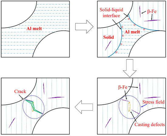
Figure 13. Sketches of crack initiation during casting in position 1.Figure 13 showed the sketches of crack initiation in position 1. During the casting process, the solid-liquid interface converged at position 1. The improper solidification sequence impeded solidification feeding in position 1, and two interfaces’ interaction could cause air entrainment. As a result, casting defects emerged in position 1. Since the solidification feeding was hindered, the solidification contraction induced stress field in this region. Plate-shaped β-Fe precipitated in Al alloy. In the stress field, the elasticity and plasticity incompatibility between β-Fe and Al matrix lead to crack initiation in these regions. The presence of casting defects facilitated crack coalescence with each other in the stress field. Therefore, cracks were frequently found in position 1.
5. Summary and Conclusions
The microstructure observation and numerical simulation were used to study the secondary dendrite arm spacing and solidification sequence in AC4B casting components that had a complex structure, and the casting defects of the components were also observed. The following conclusions have been made:
- Little oxygen was detected in the casting defects with the size of 300–500 μm that can only be found near the surface of the components. Shrinkage porosities was one of the main casting defects.
- Fe-bearing bulk was found in crack surface, the cracked big compound with many cleavage-liked features. The brittle Fe-bearing phase would promote crack initiation in service, and lead to deteriorative mechanical properties.
- The secondary dendrite arm spacing in five typical positions were significantly different. The secondary dendrite arm spacing in position 5 is smaller than that in position 1. The variation of secondary dendrite arm spacing is related to cooling rate during casting.
- Numerical simulation showed that during the casting process the cooling rate in position 5 in faster than position 1. Position 5 solidified before position 1. The solidification feeding of position 1 would be impeded, and it may lead to casting defects or even cast cracks.
Author Contributions
Methodology, Q.D. and D.Z.; software, D.Y.; data curation, W.Y. and S.Z.; writing—original draft preparation, D.Y. and Q.D.; writing—review and editing, D.Y. and Q.D.; supervision, D.Z.; project administration, W.D. All authors have read and agreed to the published version of the manuscript.
Funding
This research received no external funding.
Institutional Review Board Statement
Not applicable.
Informed Consent Statement
Not applicable.
Data Availability Statement
The data that support the findings of this study are available from the corresponding author, upon reasonable request.
Acknowledgments
This work was sponsored by Zhicheng Company, Chongqing Science and Technology Commission (cstc2018jcyjAX0607, cstc2019jcyj-msxmX0284), Scientific and Technological Research Program of Chongqing Municipal Education Commission (KJQN201801523), Project funded by China Postdoctoral Science Foundation (2019M653317, 2016T90831, 2015M572447), Chongqing Talent Project (CQYC201905100). The contribution of Daliang Yu and Wen Yang is the same.
Conflicts of Interest
The authors declare no conflict of interest.
References
- Zhu, X.; Blake, P.; Dou, K.; Ji, S. Strengthening die-cast Al-Mg and Al-Mg-Mn alloys with Fe as a beneficial element. Mater. Sci. Eng. A 2018, 732, 240–250. [Google Scholar] [CrossRef]
- Eskin, D.G.; Suyitno; Katgerman, L. Mechanical properties in the semi-solid state and hot tearing of aluminium alloys. Prog. Mater. Sci. 2004, 49, 629–711. [Google Scholar] [CrossRef]
- Basak, C.B.; Meduri, A.; Hari Babu, N. Influence of Ni in high Fe containing recyclable Al-Si cast alloys. Mater. Design. 2019, 182, 108017. [Google Scholar] [CrossRef]
- Lin, B.; Zhang, W.; Zheng, X.; Zhao, Y.; Lou, Z.; Zhang, W. Developing high performance mechanical properties at elevated temperature in squeeze cast Al-Cu-Mn-Fe-Ni alloys. Mater. Charact. 2019, 150, 128–137. [Google Scholar] [CrossRef]
- Puncreobutr, C.; Lee, P.D.; Kareh, K.M.; Connolley, T.; Fife, J.L.; Phillion, A.B. Influence of Fe-rich intermetallics on solidification defects in Al-Si-Cu alloys. Acta Mater. 2014, 68, 42–51. [Google Scholar] [CrossRef]
- Liu, K.; Chen, X.G. Influence of the modification of iron-bearing intermetallic and eutectic Si on the mechanical behavior near the solidus temperature in Al-Si-Cu 319 cast alloy. Phys. B Condens. Matter. 2019, 560, 126–132. [Google Scholar] [CrossRef]
- Xiong, J.; Yan, H.; Zhong, S.; Bi, M. Effects of Yb Addition on the Microstructure and Mechanical Properties of As-Cast ADC12 Alloy. Metals 2019, 9, 108. [Google Scholar] [CrossRef]
- Lin, B.; Xia, S.; Li, H.; Lou, Z.; Liu, K.; Zhang, W. Improved creep resistance of Al-Cu-Mn-Fe-Ni alloys through squeeze casting. Mater. Charact. 2019, 158, 109935. [Google Scholar] [CrossRef]
- Alvarez-Antolin, F.; Asensio-Lozano, J.; Cofiño-Villar, A.; Gonzalez-Pociño, A. Analysis of Different Solution Treatments in the Transformation of β-AlFeSi Particles into α-(FeMn)Si and Their Influence on Different Ageing Treatments in Al-Mg-Si Alloys. Metals 2020, 10, 620. [Google Scholar] [CrossRef]
- Li, Y.; Li, H.; Katgerman, L.; Du, Q.; Zhang, J.; Zhuang, L. Recent advances in hot tearing during casting of aluminium alloys. Prog. Mater. Sci. 2020, 100741. [Google Scholar] [CrossRef]
- Suyitno; Savran, V.I.; Katgerman, L.; Eskin, D.G. Effects of alloy composition and casting speed on structure formation and hot tearing during direct-chill casting of Al-Cu alloys. Metall. Mater. Trans. A 2004, 35, 3551–3561. [Google Scholar] [CrossRef]
- Giraud, E.; Suery, M.; Coret, M. Mechanical Behavior of AA6061 Aluminum in the Semisolid State Obtained by Partial Melting and Partial Solidification. Metall. Mater. Trans. A 2010, 41, 2257–2268. [Google Scholar] [CrossRef]
- Elsebaie, O.; Samuel, A.M.; Samuel, F.H.; Doty, H.W. Impact toughness of Al-Si-Cu-Mg-Fe cast alloys: Effects of minor additives and aging conditions. Mater. Design. 2014, 60, 496–509. [Google Scholar] [CrossRef]
- Osório, W.R.; Garcia, L.R.; Goulart, P.R.; Garcia, A. Effects of eutectic modification and T4 heat treatment on mechanical properties and corrosion resistance of an Al-9wt%Si casting alloy. Mater. Chem. Phys. 2007, 106, 343–349. [Google Scholar] [CrossRef]
- Yi, J.Z.; Gao, Y.X.; Lee, P.D.; Lindley, T.C. Effect of Fe-content on fatigue crack initiation and propagation in a cast aluminum-silicon alloy (A356-T6). Mater. Sci. Eng. A 2004, 386, 396–407. [Google Scholar] [CrossRef]
- Roy, N.; Samuel, A.M.; Samuel, F.H. Porosity formation in AI-9 Wt Pct Si-3 Wt Pct Cu alloy systems: Metallographic observations. Metall. Mater. Trans. A 1996, 27, 415–429. [Google Scholar] [CrossRef]
- Chen, R.; Shi, Y.; Xu, Q.; Liu, B. Effect of cooling rate on solidification parameters and microstructure of Al-7Si-0.3Mg-0.15Fe alloy. Trans. Nonferr. Metal. Soc. 2014, 24, 1645–1652. [Google Scholar] [CrossRef]
- Patakham, U.; Limmaneevichitr, C. Effects of iron on intermetallic compound formation in scandium modified Al-Si-Mg Alloys. J. Alloy. Compd. 2014, 616, 198–207. [Google Scholar] [CrossRef]
- Sweet, L.; Easton, M.A.; Taylor, J.A.; Grandfield, J.F.; Davidson, C.J.; Lu, L.; Couper, M.J.; StJohn, D.H. Hot Tear Susceptibility of Al-Mg-Si-Fe Alloys with Varying Iron Contents. Metall. Mater. Trans. A 2013, 44, 5396–5407. [Google Scholar] [CrossRef]
- Bjurenstedt, A.; Ghassemali, E.; Seifeddine, S.; Dahle, A.K. The effect of Fe-rich intermetallics on crack initiation in cast aluminium: An in-situ tensile study. Mater. Sci. Eng. A 2019, 756, 502–507. [Google Scholar] [CrossRef]
- Dinnis, C.M.; Taylor, J.A.; Dahle, A.K. Iron-related porosity in Al-Si- (Cu) foundry alloys. Mater. Sci. Eng. A 2006, 425, 286–296. [Google Scholar] [CrossRef]
- Wu, X.; Zhang, H.; Ma, Z.; Tao, T.; Gui, J.; Song, W.; Yang, B.; Zhang, H. Interactions between Fe-rich intermetallics and Mg-Si phase in Al-7Si-xMg alloys. J. Alloy. Compd. 2019, 786, 205–214. [Google Scholar] [CrossRef]
- Bolouri, A.; Liu, K.; Chen, X.G. Effects of Iron-Rich Intermetallics and Grain Structure on Semisolid Tensile Properties of Al-Cu 206 Cast Alloys near Solidus Temperature. Metall. Mater. Trans. A 2016, 47, 6466–6480. [Google Scholar] [CrossRef]
- Couture, A. Iion in aluminum casting alloys-a literature survey. Int. Cast Met. J. 1981, 6, 9–17. [Google Scholar]
- Beroual, S.; Boumerzoug, Z.; Paillard, P.; Borjon-Piron, Y. Effects of heat treatment and addition of small amounts of Cu and Mg on the microstructure and mechanical properties of Al-Si-Cu and Al-Si-Mg cast alloys. J. Alloy. Compd. 2019, 784, 1026–1035. [Google Scholar] [CrossRef]
- Wang, E.R.; Hui, X.D.; Wang, S.S.; Zhao, Y.F.; Chen, G.L. Improved mechanical properties in cast Al–Si alloys by combined alloying of Fe and Cu. Mater. Sci. Eng. A 2010, 527, 7878–7884. [Google Scholar] [CrossRef]
- Mohseni, S.M.; Phillion, A.B.; Maijer, D.M. Modelling the constitutive behaviour of aluminium alloy B206 in the as-cast and artificially aged states. Mater. Sci. Eng. A 2016, 649, 382–389. [Google Scholar] [CrossRef]
- Moustafa, M.A.; Samuel, F.H.; Doty, H.W.; Valtierra, S. Effect of Mg and Cu additions on the microstructural characteristics and tensile properties of Sr-modified Al-Si eutectic alloys. Int. J. Cast Metal. Res. 2002, 14, 235–253. [Google Scholar] [CrossRef]
- Liu, K.; Cao, X.; Chen, X.G. Tensile Properties of Al-Cu 206 Cast Alloys with Various Iron Contents. Metall. Mater. Trans. A 2014, 45, 2498–2507. [Google Scholar] [CrossRef]
- Seifeddine, S.; Johansson, S.; Svensson, I.L. The influence of cooling rate and manganese content on the β-Al5FeSi phase formation and mechanical properties of Al-Si-based alloys. Mater. Sci. Eng. A 2008, 490, 385–390. [Google Scholar] [CrossRef]
- Mohamed, A.M.A.; Samuel, F.H.; Kahtani, S.A. Microstructure, tensile properties and fracture behavior of high temperature Al-Si-Mg-Cu cast alloys. Mater. Sci. Eng. A 2013, 577, 64–72. [Google Scholar] [CrossRef]
- Zamani, M.; Seifeddine, S.; Jarfors, A.E.W. High temperature tensile deformation behavior and failure mechanisms of an Al-Si-Cu-Mg cast alloy–The microstructural scale effect. Mater. Design. 2015, 86, 361–370. [Google Scholar] [CrossRef]
- Espinoza-Cuadra, J.; García-García, G.; Mancha-Molinar, H. Influence of defects on strength of industrial aluminum alloy Al-Si 319. Mater. Design. 2007, 28, 1038–1044. [Google Scholar] [CrossRef]
- Zhu, M.; Jian, Z.; Yang, G.; Zhou, Y. Effects of T6 heat treatment on the microstructure, tensile properties, and fracture behavior of the modified A356 alloys. Mater. Design. 2012, 36, 243–249. [Google Scholar] [CrossRef]
- Cui, X.; Yu, Z.; Liu, F.; Du, Z.; Bai, P. Influence of secondary phases on crack initiation and propagation during fracture process of as-cast Mg-Al-Zn-Nd alloy. Mater. Sci. Eng. A 2019, 759, 708–714. [Google Scholar] [CrossRef]