This introduction paper is based on the paper "Strength of Salt Core Composed of Alkali Carbonate and Alkali Chloride Mixtures Made by Casting Technique" published by "Materials Transactions / Japan Foundary Engineering Society".
1. Overview:
- Title: Strength of Salt Core Composed of Alkali Carbonate and Alkali Chloride Mixtures Made by Casting Technique
- Author: Jun Yaokawa, Daisuke Miura, Koichi Anzai, Youji Yamada and Hiroshi Yoshii
- Year of publication: 2007
- Journal/academic society of publication: Materials Transactions / Japan Foundary Engineering Society
- Keywords: salt core, expendable core, carbonate, chloride, die casting, strength, microstructure
2. Abstract:
The strength of four binary systems NaCl-Na2CO3, KCI-K2CO3, KCI-NaCl and K2CO3-Na2CO3 was investigated in order to develop expendable salt core for high pressure die casting processes. Four point bending test was conducted to determine the strength of specimens made from molten salts by using the permanent mold casting technique. The strength of the system NaCl-Na2CO3 was over 20 MPa at the Na2CO3 composition between 20 mol% and 30 mol%, and between 50 mol% and 70 mol%. The highest strength was about 30 MPa at the composition of NaCl-70 mol%Na2CO3. This strength was 5 times as high as that of commonly used sand cores. The system KCI-K2CO3 also showed 20 MPa in strength. It was observed that there were the primary particles surrounded by the eutectic structure in the solidification structure of the systems NaCl-Na2CO3 and KCI-K2CO3 at the composition where the peak strength was obtained. The presence of the primary particles played an important role to strengthen the structure because the primary particles can prevent or deflect the crack propagation. In contrast to these binary systems, the systems KCI-NaCl and K2CO3-Na2CO3 were very brittle due to the phase decomposition or other solid-solid phase transformation of the solid solution phase. The strength of these systems was under 6 MPa.
3. Introduction:
High pressure die casting (HPDC) is a cost-effective manufacturing process for near-net-shape, geometrically complex aluminum alloy components. Fabricating parts with undercut shapes using HPDC requires expendable cores, but the severe casting conditions (high flow velocity > 30 m/s, high hydrostatic pressure > 60 MPa) demand cores with very high strength. However, increasing core strength typically reduces collapsibility, leading to longer removal times and increased costs. Various expendable cores (sand, metallic, organic, salt) have been developed, but none fully satisfy both strength and removability requirements for HPDC.
Water-soluble salt cores made by casting techniques are attractive due to their high removability and the ability to form complex shapes. While reinforced salt cores (e.g., alkali halides with aluminum borate whiskers) show high strength, they suffer from reduced melt fluidity, increased material costs, and recycling challenges. Patents suggest unreinforced salt mixtures offer good castability and removability, making them desirable. However, systematic studies on the strength of these salt mixtures are limited. This study aims to fill that gap by investigating the strength of four binary salt systems relevant to aluminum HPDC: sodium chloride-sodium carbonate (NaCl-Na2CO3), potassium chloride-potassium carbonate (KCl-K2CO3), potassium chloride-sodium chloride (KCl-NaCl), and potassium carbonate-sodium carbonate (K2CO3-Na2CO3).
4. Summary of the study:
Background of the research topic:
There is an increasing need for high-strength, easily removable expendable cores for producing complex, undercut components via the HPDC process, particularly for aluminum alloys. Water-soluble salt cores are a promising candidate technology.
Status of previous research:
Previous research explored reinforced salt cores, which achieved high strength but faced issues with cost, melt fluidity, and recycling. Patents indicated potential for unreinforced salt mixtures, but systematic data on their strength properties, especially concerning the effect of composition, was lacking.
Purpose of the study:
The study aimed to systematically investigate the strength of four binary salt systems (NaCl-Na2CO3, KCl-K2CO3, KCl-NaCl, K2CO3-Na2CO3) fabricated by a permanent mold casting method. The goal was to understand the relationship between salt mixture composition, solidification structure, and mechanical strength, identifying compositions suitable for HPDC salt cores.
Core study:
The core of the study involved preparing specimens from the four binary salt systems across a range of compositions using permanent mold casting. The mechanical strength of these as-cast specimens was determined using four-point bending tests. Solidification microstructures and fracture surfaces were analyzed using SEM, EDX, and XRD to correlate structure with strength. Phase diagrams were used to interpret the solidification behavior and resulting microstructures. Vickers hardness was also measured.
5. Research Methodology
Research Design:
The research employed an experimental design. It involved preparing various compositions of four binary salt systems, casting them into standardized test specimens using a permanent mold, measuring their bending strength and hardness, and analyzing their microstructure and fracture behavior to understand the underlying mechanisms determining strength.
Data Collection and Analysis Methods:
- Materials: Pure salts (NaCl, KCl, Na2CO3, K2CO3, 99.5 mass% purity) were mixed to create binary systems with varying compositions (Table 1).
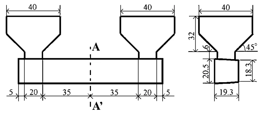
- Specimen Fabrication: Salt mixtures were melted, superheated 10K above their liquidus temperature, and poured into a preheated (373 K) JIS-SCM440 steel permanent mold (Fig. 1) with risers. Specimens were ejected after 60 seconds and cooled.
- Mechanical Testing: Four-point bending tests were performed on as-cast specimens (dimensions specified, bending rate 1.6 x 10⁻² mm·s⁻¹) to determine maximum bending force (P) and calculate bending strength (σ) using eq. (1). Vickers hardness was measured on polished cross-sections.
- Microstructural Analysis: Solidified structures were observed using Scanning Electron Microscopy (SEM) on polished and etched samples. Energy Dispersive X-ray microanalysis (EDX) determined local compositions. X-ray Diffraction (XRD) identified crystalline phases. Fracture surfaces were analyzed using SEM-EDX.
- Phase Diagrams: Calculated using Thermo-Calc™ software.
Research Topics and Scope:
The study focused on the bending strength and microstructure of four binary alkali chloride-alkali carbonate salt systems (NaCl-Na2CO3, KCl-K2CO3, KCl-NaCl, K2CO3-Na2CO3) prepared by permanent mold casting. The scope included investigating the effect of composition on strength and hardness, identifying solidification structures, analyzing casting defects (unevenness, internal shrinkage, Fig. 2), and elucidating strengthening mechanisms based on microstructure and fracture analysis. The strength analysis was performed on as-cast specimens containing typical casting defects.
6. Key Results:
Key Results:
- The binary systems KCl-NaCl and K2CO3-Na2CO3 exhibited very low strength (under 6 MPa) and were brittle, showing significant cracking (Fig. 3). This was attributed to solid-solid phase transformations (decomposition or eutectoid reactions) occurring in their continuous solid solution structures during cooling (Fig. 4).
- The NaCl-Na2CO3 system demonstrated high strength, exceeding 20 MPa for Na2CO3 compositions between 20-30 mol% and 50-70 mol%. The peak strength was over 30 MPa at NaCl-70 mol%Na2CO3, approximately 5 times higher than common sand cores (Fig. 5b).
- The KCl-K2CO3 system also showed significant strength, exceeding 10 MPa at 20 mol% K2CO3 and between 50-80 mol% K2CO3. The highest strength reached over 25 MPa at K2CO3 compositions of 50 mol% and 60 mol% (Fig. 5d).
- High strength in the NaCl-Na2CO3 and KCl-K2CO3 systems correlated with compositions resulting in a microstructure consisting of primary phase particles (either chloride or carbonate) dispersed within a eutectic matrix (Fig. 7, Fig. 11e). Strength was lowest near pure components and at the eutectic composition itself (Fig. 11a, 11c).
- The strengthening in high-strength compositions was attributed to the primary particles hindering crack propagation via "crack deflection" along cleavage planes (Fig. 9a, Fig. 10b) and "crack bowing" around the particles (Fig. 9b, Fig. 10a), as schematically shown in Fig. 11f.
- Vickers hardness measurements (Fig. 6) showed that the NaCl-Na2CO3 system was generally harder than the KCl-K2CO3 system across the composition range, consistent with its higher overall strength. Hardness of both primary particles and the eutectic structure plays a role in the overall strength.
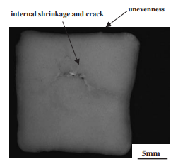
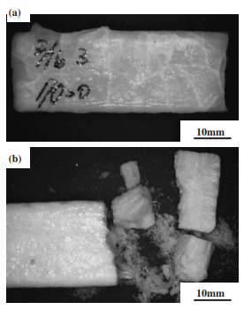
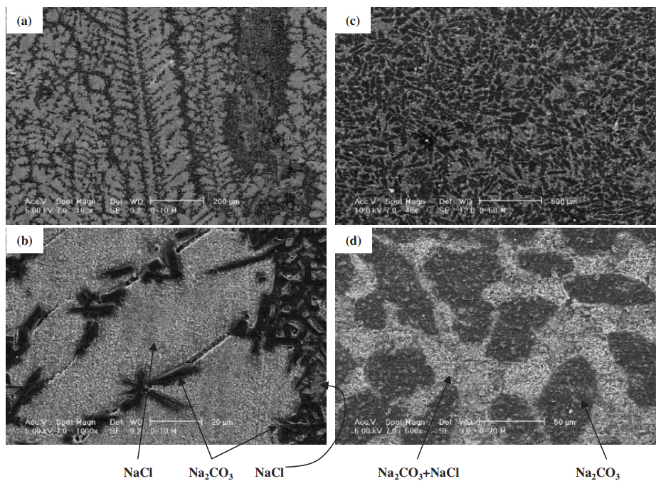
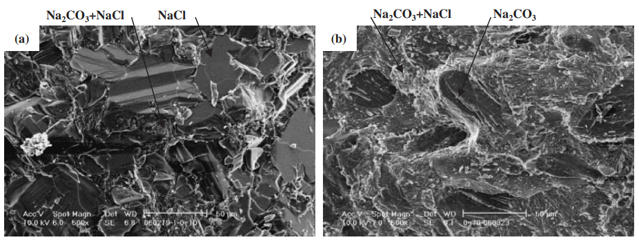
Figure Name List:
- Fig. 1 Casting design of bending test specimens.
- Fig. 2 Cross section of KCl-80 mol%K2CO3 specimen.
- Fig. 3 Photographs of specimens at ambient temperature. (a) KC1-30 mol%NaCl. (b) K2CO3-50 mol% Na2CO3.
- Fig. 4 Strength and phase diagrams¹⁵⁾ of KCl-NaCl and K2CO3-Na2CO3 binary systems.
- Fig. 5 Strength and phase diagrams¹⁵⁾ of NaCl-Na2CO3 and KCl-K2CO3 binary systems.
- Fig. 6 Vickers hardness of the system NaCl-Na2CO3 and the system KCI-K2CO3. Solid and dotted lines connect average hardness value of each composition, respectively.
- Fig. 7 The scanning electron microscope (SEM) images of solidified structure. (a) and (b): NaCl-10 mol%Na2CO3. (c) and (d): NaCl-70 mol%Na2CO3.
- Fig. 8 The X-ray diffraction pattern of NaCl-70 mol% Na2CO3.
- Fig. 9 The scanning electron microscope (SEM) images of broken surface. (a): NaCl-10mol%Na2CO3. (b): NaCl-70 mol%Na2CO3.
- Fig. 10 Schematic drawings of two strengthening mechanisms²⁰⁾ in the systems NaCl-Na2CO3 and KCI-K2CO3. (a) crack bowing. (b) crack deflection.
- Fig. 11 Schematic drawings of the solidification structure and the crack propagation. (a) and (b): at the eutectic composition. (c) and (d): pure salt. (e) and (f): the composition between the eutectic and the unary.
7. Conclusion:
The study investigated the strength of four binary salt systems (NaCl-Na2CO3, KCl-K2CO3, KCl-NaCl, K2CO3-Na2CO3) cast using a permanent mold technique, analyzing microstructure with SEM-EDX and XRD. Key findings are:
- The NaCl-Na2CO3 system achieved strength over 20 MPa between 20-30 mol% and 50-70 mol% Na2CO3, with a maximum strength exceeding 30 MPa at NaCl-70 mol%Na2CO3.
- The KCl-K2CO3 system showed strength over 10 MPa at 20 mol% K2CO3 and between 50-60 mol% K2CO3, with a maximum strength exceeding 25 MPa at 50-60 mol% K2CO3.
- The increased strength in NaCl-Na2CO3 and KCl-K2CO3 systems resulted from their solidification structure, where primary particles within the eutectic matrix effectively prevented or deflected crack propagation.
- The NaCl-Na2CO3 system exhibited higher strength than the KCl-K2CO3 system, attributed to the higher hardness values of its primary particles and eutectic structure.
- The KCl-NaCl and K2CO3-Na2CO3 systems displayed low strength (lower than 6 MPa) due to their solidification structure (continuous solid solution) and detrimental solid-solid phase transformations during cooling.
8. References:
- [1) T. Manabe, M. Nitta and M. Yaguchi: SOKEIZAI 44 (2003) 26–30.
- 2) Yamazaki, A. Takai, O. Murakami, M. Kawabata, O. Ito and M. Kawabata: SAE Technical Paper 2004-01-1447.
- 3) Y. Mizukusa: U.S. Patent No. 5,690,159 (Jun. 20, 1997).
- 4) K. Fujita and K. Atake: Japanese Patent Publication No. H9-108779 (Apr. 28, 1997).
- 5) T. Sakoda: U.S. Patent No. 3,963,818 (Jun. 15, 1976).
- 6) W. A. Gibbons: U.S. Patent 1,523,519 (Feb. 12, 1924).
- 7) F. D. Obolentsev, V. A. Voznesenskii, L. A. Ivanova and I. D. Chmykh: Chem. Petroleum Eng. 13 (1977) 519–521.
- 8) Y. Utsu: Japanese Patent Publication No. 52-10803 (Mar. 26, 1977).
- 9) R. W. Foreman: U. S. Patent No. 4,840,219 (Jun. 20, 1989).
- 10) A. D. Ackerman, H. A. Aula: U.S. Patent 4,446,906 (May 8, 1984).
- 11) Y. Urabe and K. Takeda: Japanese Patent Publication, No. 48-39696 (Nov. 26, 1973).
- 12) J. Yaokawa, K. Anzai, Y. Yamada, H. Yoshii and H. Fukui: J. JFS, 76 (2004) 823–829.
- 13) J. Yaokawa, K. Anzai, Y. Yamada and H. Yoshii: NADCA Transactions T05-083 (2005).
- 14) General editors, L. P. Cook and H. F. McMurdie: Phase diagrams for ceramists vol. 1, Fig. 1857 (The American Ceramic Society, Columbus, Ohio, 1964).
- 15) B. Sundman, B. Jansson, J.-O. Andersson: Calphad 9 (1985) 153–190.
- 16) S. Dong, E. Niyama and K. Anzai: Cast Metals 6 (1993) 115–120.
- 17) S. Pehkonen: J. Phys. D: Appl. Phys. 6 (1973) 544–551.
- 18) L. P. Cook and H. F. Mcmurdie: Phase Diagrams for Ceramists vol. 7, Fig. 6976 (The American Ceramic Society, Columbus, Ohio, 1976) pp. 16–17.
- 19) A. Reisman: J. Am. Chem. Soc. 81 (1959) 807–811.
- 20) Y. Kagawa and H. Hatta: Ceramic Matrix Composites—Tailoring Ceramic Composites, (Agune Shohusha, 1990) 120–157.
- 21) C. Gandhi and M. F. Ashby: Acta Metall. 27 (1979) 1565.
- 22) E. Scheil: Z. Metallk. 34 (1942) 70.
- 23) J. Sangster and A. D. Pelton: J. Phys. Chem. Ref. Data 16 (1987) 509.]
9. Copyright:
- This material is a paper by "Jun Yaokawa, Daisuke Miura, Koichi Anzai, Youji Yamada and Hiroshi Yoshii". Based on "Strength of Salt Core Composed of Alkali Carbonate and Alkali Chloride Mixtures Made by Casting Technique".
- Source of the paper: https://doi.org/10.2320/matertrans.48.1034
This material is summarized based on the above paper, and unauthorized use for commercial purposes is prohibited.
Copyright © 2025 CASTMAN. All rights reserved.