This technical summary is based on the academic paper "TECHNOLOGICAL STEPS IN THE MANUFACTURING OF THE BRACKET TYPE AUTOMOTIVE PARTS WITH THE HIGH PRESSURE DIE CASTING TECHNOLOGY" published by Ferencz Peti, Lucian Grama, and Ioan Solovăstru in the ANNALS of the ORADEA UNIVERSITY (2011). It was analyzed and summarized for HPDC experts by CASTMAN experts with the help of LLM AI such as Gemini, ChatGPT, and Grok.

Keywords
- Primary Keyword: HPDC manufacturing process
- Secondary Keywords: Process flowchart, Production cell layout, Automotive bracket manufacturing, High pressure die casting, CNC machining process, Die casting technology, Aluminium
Executive Summary
- The Challenge: Automotive OEMs increasingly require suppliers to provide clearly defined manufacturing flowcharts and industrial layouts, even during the initial quotation phase, to ensure process capability and control.
- The Method: The research outlines a comprehensive, step-by-step manufacturing process for automotive brackets using high-pressure die casting (HPDC), documented through detailed process flowcharts and production cell layouts.
- The Key Breakthrough: The paper provides a complete visual blueprint for the entire production cycle, detailing every stage from raw material reception and casting to CNC machining, assembly, and final delivery, including specific equipment and quality control checkpoints.
- The Bottom Line: A well-defined and documented process flow and layout are fundamental tools for optimizing production, eliminating waste, ensuring consistent quality, and meeting stringent customer requirements in the competitive automotive sector.
The Challenge: Why This Research Matters for HPDC Professionals
In today's demanding automotive industry, simply producing a quality part is not enough. OEMs require their suppliers to demonstrate a deep understanding and control over the entire manufacturing process. As highlighted in the paper's introduction, manufacturers must "define clearly even in technical study for quotation phase the manufacturing flowcharts and industrial layouts for the technological operations." This requirement places the burden on HPDC professionals to have a robust, repeatable, and well-documented system. Without this, securing new business and maintaining customer trust becomes a significant challenge. This paper addresses this need directly by providing a clear and structured model for defining the manufacturing process of a common automotive component: the bracket.
The Approach: Unpacking the Methodology
The researchers present a systematic approach to defining the manufacturing process by breaking it down into its core components and documenting them through two primary tools:
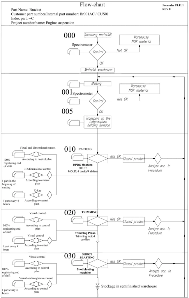
- Process Flowcharts: These diagrams represent the algorithm of production, showing each step in a logical sequence. The paper provides a high-level flowchart (Figure 2.1) and then drills down into detailed flowcharts for the casting process (Figure 2.2) and the machining process (Figure 2.3).
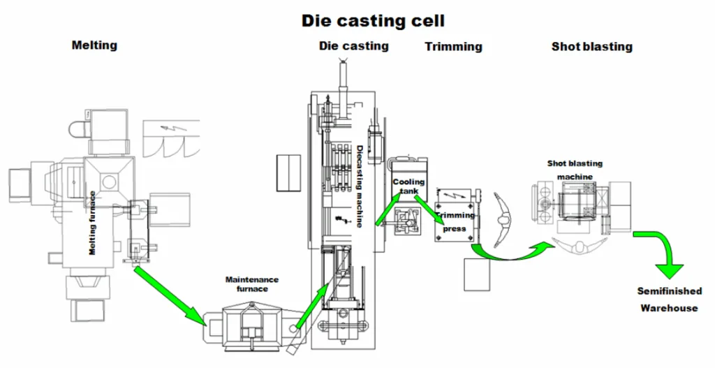
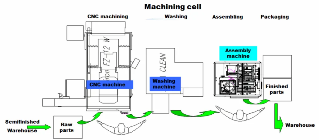
- Production Cell Layouts: These floor plans illustrate the physical arrangement of equipment to improve efficiency. The study presents layouts for both the die casting cell (Figure 3.1) and the machining cell (Figure 3.2), showcasing an optimized flow of materials and parts.
The methodology identifies the key industrial equipment for each stage. The casting cell includes melting and maintenance furnaces, the HPDC machine, a part extraction robot, a trimming press, and a shot blasting machine. The machining cell is centered around a CNC machine, a washing machine, and an assembly machine.
The Breakthrough: Key Findings & Data
The core value of this research is its detailed and practical documentation of a complete manufacturing cycle.
- Finding 1: A Complete End-to-End Process Map: The paper establishes a clear, sequential master process flow, starting with material reception and moving through warehousing, melting, die casting, trimming, shot blasting, CNC machining, washing, assembly, packaging, and finally, delivery. This is clearly visualized in Figure 2.1.
- Finding 2: Granular Detail in the Casting Process: The flowchart in Figure 2.2 breaks down the casting stage into discrete operations (000 to 030). It specifies not just the steps (e.g., "CASTING," "TRIMMING") but also the equipment used (e.g., "HPDC Machine 600 Tn," "Trimming Press") and, critically, the integrated quality control loops. For instance, it mandates spectrometer checks on incoming material, X-ray analysis on initial castings, and visual checks at multiple points.
- Finding 3: A Structured Machining and Assembly Flow: Following casting, the machining process is detailed in Figure 2.3 (operations 040 to 080). This flowchart outlines the CNC machining, washing, and assembly steps, again specifying the machinery ("CNC Machine," "Assembly Machine") and the necessary quality controls, such as dimensional checks every two hours and visual inspections.
- Finding 4: Optimized Physical Workflow: The manufacturing cell layouts in Figure 3.1 (Die Casting) and Figure 3.2 (Machining) translate the process flow into a physical reality. They show an efficient arrangement of equipment designed to minimize material movement, streamline operations, and create a logical path from raw material to semifinished and finished parts.
Practical Implications for HPDC Products
This paper is more than an academic exercise; it's a practical guide for improving real-world manufacturing operations.
- For Process Engineers: The detailed flowcharts in Figure 2.2 and Figure 2.3 serve as an excellent template for documenting your own production processes. Using this structure can help identify inefficiencies, standardize operations across shifts, and ensure every critical step is performed consistently.
- For Quality Control: The paper explicitly integrates quality checks at every critical stage (e.g., "X-Ray," "Visual and dimensional control," "Control by sampling"). This provides a robust framework for developing a comprehensive quality assurance plan that catches potential defects early, reducing scrap and rework costs.
- For Plant Managers & Industrial Engineers: The principles of an effective process layout, outlined on page 2 and visualized in Figures 3.1 and 3.2, are directly applicable to any plant floor. By arranging equipment to "minimize material handling costs," "eliminate bottlenecks," and "utilize space efficiently," you can significantly improve overall operational efficiency.
Paper Details
TECHNOLOGICAL STEPS IN THE MANUFACTURING OF THE BRACKET TYPE AUTOMOTIVE PARTS WITH THE HIGH PRESSURE DIE CASTING TECHNOLOGY
1. Overview:
- Title: TECHNOLOGICAL STEPS IN THE MANUFACTURING OF THE BRACKET TYPE AUTOMOTIVE PARTS WITH THE HIGH PRESSURE DIE CASTING TECHNOLOGY
- Author: Ferencz Peti, Lucian Grama, Ioan Solovăstru
- Year of publication: 2011
- Journal/academic society of publication: ANNALS of the ORADEA UNIVERSITY. Fascicle of Management and Technological Engineering, Volume X (XX), 2011, NR2
- Keywords: bracket, high pressure die casting, die casting machine, mold, aluminium, flowchart, layout
2. Abstract:
The paper presents the main technological steps in the manufacturing of the “bracket type" automotive parts with the high pressure diecasting technology and the elements of the manufacturing process. The manufacturing process definition has as main steps the definition of the process flow chart and the definition of the manufacturing process layout.
3. Introduction:
From the early design stage of automotive bracket type parts, it is necessary to analyze and consider the main technological operations that will add value. Most OEMs require their suppliers to clearly define, even in the technical study for the quotation phase, the manufacturing flowcharts and industrial layouts for these operations. The technological steps are defined within the flowchart and layout.
4. Summary of the study:
Background of the research topic:
The research is set against the backdrop of the automotive industry's stringent requirements for suppliers. Manufacturers of HPDC parts, like brackets, must provide detailed documentation of their production processes to prove capability and control, often as a prerequisite for winning contracts.
Status of previous research:
The paper does not review previous literature but instead focuses on presenting a standardized, best-practice methodology for process definition, drawing on established industrial engineering principles for flowcharts and layouts.
Purpose of the study:
The purpose is to present and define the main technological steps, process flow, and physical layout for manufacturing "bracket type" automotive parts using the HPDC process. The goal is to provide a clear, structured, and visual guide to this manufacturing system.
Core study:
The core of the study is the detailed presentation of the manufacturing process, broken down into two main cells: the Die Casting Cell and the Machining Cell. For each, the paper provides a list of main equipment and tools, a detailed process flowchart with integrated quality control steps, and a visual layout of the production cell.
5. Research Methodology
Research Design:
The research design is descriptive and illustrative. It involves the systematic breakdown of a complex manufacturing process into its constituent steps and physical arrangement. The authors use standard industrial engineering tools—process flowcharts and equipment layouts—to document and explain the production system.
Data Collection and Analysis Methods:
The "data" in this study consists of the procedural steps, equipment specifications, quality control points, and spatial arrangements that constitute the manufacturing process for an automotive bracket. The analysis involves organizing this information into logical, easy-to-understand diagrams (flowcharts and layouts).
Research Topics and Scope:
The scope is focused specifically on the manufacturing of aluminum bracket-type parts for the automotive industry via high-pressure die casting. It covers the entire production flow from raw material receipt to final packaging and delivery, including both the casting and subsequent machining operations.
6. Key Results:
Key Results:
- A comprehensive process flowchart detailing the entire manufacturing sequence from material reception to delivery.
- A detailed sub-flowchart for the casting process, including melting, casting, trimming, and shot blasting, with specific quality control checks defined.
- A detailed sub-flowchart for the machining process, including CNC machining, washing, assembly, and packaging, also with defined quality checks.
- A visual layout for an efficient high-pressure die casting cell.
- A visual layout for an efficient CNC machining cell.
Figure Name List:


- Figure. 2.1. Order of the industrial manufacturing steps of the bracket type automotive parts with the high pressure diecasting technology
- Figure. 2.2. Flowchart of the casting process for a bracket type of part.
- Figure. 2.3. Flowchart of the machining process for a bracket type of part
- Figure. 3.1. Manufacturing cell layout for high pressure diecasting process
- Figure. 3.2. Manufacturing cell layout for machining process
7. Conclusion:
By defining the process flow chart and the manufacturing process layout a clear picture about the manufacturing process of the bracket type of parts is given. This is beneficial for all the departments of the organization as well as for the relation with the customer. Once they exist, the process flow chart and the manufacturing process layout can be and usually are optimized in order to eliminate waste and to reduce or to optimize the manufacturing costs.
8. References:
- [1] Ernst Brunhuber – Praxis der Druckgussfertigung, Editura Schiele&Schon, Berlin, 1991
- [2] Herbert Rees – Mold Engineering, Editura Carl Hanser Verlag, Munich, 2002
- [3] Montes Jose - Curso Básico Fundición a Presión, CIEAutomotive, 2010
- [4] Montes Jose - Revision Tecnica del Producto, CIE C. Vilanova, 2008
- [5] Montes Jose - Tecnicas de Fundicion a Presion, CIEAutomotive, 2010
- [6] Street, Arthur, The diecasting handbook, Portcullis Press LTD, 1977
- [7] Şontea S., ş.a. Metale şi aliaje neferoase de turnătorie, Editura Scrisul Românesc, Craiova, 1981.
- [8] Zirbo, Gh., Dan V. – Turnarea sub presiune. Elemente de proiectare a formelor metalice, Editura U.T. Pres, Cluj-Napoca, 1997
- [9] * - Company documentation Bühler
- [10] * - Company documentation Idra
- [11]http://books.google.ro/books?id=7od4alFKfNMC&pg=PA851&lpg=PA851&dq=industrial+layout+diecasting&source=bl&ots=TsAkEbsiRN&sig=QnXNmRbUzHqZofecENJIKSavg&hl=ro&ei=AmeTTYvPHIuLhQfj YCbDw&sa=X&oi=book_result&ct=result&resnum=2&ved=0CCcQ6AEwAQ#v=onepage&q&f=false
- [12] http://en.wikipedia.org/wiki/Process_layout
Expert Q&A: Your Top Questions Answered
Q1: Why is it so important to define a process flowchart and layout early in a project? A1: According to the paper, most OEMs require suppliers to define these documents even in the technical study for the quotation phase. This provides clarity for all stakeholders, helps in accurate cost estimation, and builds foundational trust with the customer from the very beginning (Source: Introduction, page 1).
Q2: What are the main stages in manufacturing an HPDC automotive bracket according to this paper? A2: The process is broken down into a clear sequence: Material Reception, Material Warehousing, Melting, Die Casting & Trimming, Shot Blasting, CNC Machining, Washing, Assembly, and finally Packaging and Labeling for delivery (Source: Figure 2.1).
Q3: What kind of quality control checks are integrated into the casting process? A3: The detailed flowchart for casting specifies multiple checks, including spectrometer control for incoming material and molten metal, as well as visual control, 3D dimensional control, and X-ray analysis for the cast parts at defined frequencies (e.g., "1 part every 4 hours") (Source: Figure 2.2).
Q4: What are the key pieces of equipment in a typical HPDC casting cell for this type of part? A4: The paper identifies the main industrial equipment as a Melting furnace, maintenance furnace, the high pressure diecasting machine, a robot for parts extraction, a quenching tank, a trimming press, and a shotblasting machine (Source: Page 1, Section 2).
Q5: What is the ultimate goal of creating and using a process layout? A5: The paper lists several key objectives for an effective process layout, including minimizing material handling costs, utilizing space and labor efficiently, eliminating bottlenecks, facilitating communication, and ultimately promoting product and service quality (Source: Page 2, Section 3).
Q6: How does this structured approach benefit the manufacturer in the long run? A6: The conclusion states that once a clear flowchart and layout exist, they become powerful tools for optimization. They provide the visibility needed to analyze the process, eliminate waste, and reduce or optimize manufacturing costs, leading to improved profitability and competitiveness (Source: Conclusions, page 5).
Conclusion & Next Steps
This research provides a valuable roadmap for any HPDC manufacturer looking to formalize and optimize their production processes. The findings offer a clear, data-driven path toward improving quality, demonstrating process control to customers, and creating a foundation for continuous improvement. By systematically defining each step, from the furnace to the shipping dock, companies can move from reactive problem-solving to proactive process optimization.
At CASTMAN, we are dedicated to applying the latest industry research to solve our customers' most challenging die casting problems. If the issues of process control, efficiency, and documentation discussed in this paper resonate with your operational goals, contact our engineering team to discuss how we can help you implement these advanced principles in your components.
Copyright
- This material is a paper by "Ferencz Peti, Lucian Grama, Ioan Solovăstru". Based on "TECHNOLOGICAL STEPS IN THE MANUFACTURING OF THE BRACKET TYPE AUTOMOTIVE PARTS WITH THE HIGH PRESSURE DIE CASTING TECHNOLOGY".
- Source of the paper: ANNALS of the ORADEA UNIVERSITY. Fascicle of Management and Technological Engineering, Volume X (XX), 2011, NR2.
This material is for informational purposes only. Unauthorized commercial use is prohibited. Copyright © 2025 CASTMAN. All rights reserved.