The 1mm Advantage: Optimizing Coolant Channel Placement to Maximize Die Life in Aluminum HPDC
This technical summary is based on the academic paper "Effect of Die Geometry on Fatigue Analysis of Aluminium Alloy (ADC12 Aluminium A383) using Pressure Die Casting Process" by Poshan Dewangan, Ved Prakash Dewangan, Sushil Kumar Maurya, and Lokesh Singh, published in the International Journal of Scientific Research in Civil Engineering (2021). It has been analyzed and summarized for technical experts by CASTMAN.

Keywords
- Primary Keyword: HPDC Die Life
- Secondary Keywords: Thermal Fatigue, Die Casting, Coolant Channel Design, Aluminum Alloy A383, ANSYS Simulation
Executive Summary
- The Challenge: Thermal fatigue is a primary cause of premature die failure in aluminum high-pressure die casting (HPDC), leading to costly downtime and tool replacement.
- The Method: The study used ANSYS Workbench 17.1 to conduct a finite-element thermal fatigue analysis on a die for casting A383 aluminum alloy, varying the coolant channel location from the die's base.
- The Key Breakthrough: A coolant channel located 1 mm from the base demonstrated the longest fatigue life (113,080 cycles) and lowest normal stress (241.56 MPa) compared to other tested locations.
- The Bottom Line: Strategic placement of cooling channels is a critical design factor that can significantly extend HPDC die life by optimizing the thermal-mechanical stress cycle.
The Challenge: Why This Research Matters for HPDC Professionals
In the demanding world of aluminum die casting, the service life of a die is paramount. Dies are subjected to intense, cyclic thermal loading as molten aluminum is injected, solidifies, and is ejected. This relentless heating and cooling cycle is the primary driver of thermal fatigue, which leads to the formation of cracks on the die surface.
These cracks not only degrade the surface finish of the cast parts but also propagate over time, eventually causing catastrophic die failure. The replacement of a die is a significant expense, both in terms of the tool's cost and the lost production time. For any operation focused on economical and consistent production, extending die life by mitigating thermal fatigue is a critical objective. This research directly addresses this challenge by investigating how a fundamental design choice—the geometry and location of cooling channels—can be optimized to combat thermal fatigue.
The Approach: Unpacking the Methodology
To isolate the effect of die geometry on thermal fatigue, the researchers employed a simulation-based approach using the ANSYS Workbench 17.1 finite-element package.
- Material: The study focused on the die casting of Aluminium Alloy A02240 (equivalent to ADC12/A383), a common material in the automotive and other industries.
- Analysis: A transient thermal and structural analysis was performed on a 3D CAD model of the die. This allowed for the simulation of the cyclic temperature changes and resulting stresses that occur during the casting process.
- Key Variable: The critical variable under investigation was the location of the coolant channel relative to the base of the die. The researchers analyzed six different positions: 0.5 mm, 1 mm, 2 mm, 3 mm, 4 mm, and 5 mm from the base.
- Measured Parameters: For each coolant channel location, the simulation calculated key performance indicators, including temperature distribution, normal stress, fatigue life (in cycles), fatigue damage, and equivalent alternating stress.
This robust simulation methodology provided a clear, data-driven comparison of how a simple geometric change directly impacts the factors that govern HPDC die life.
The Breakthrough: Key Findings & Data
The analysis revealed a distinct optimal zone for coolant channel placement, with significant consequences for die longevity.
Finding 1: Coolant Channel Proximity Directly Governs Die Surface Temperature
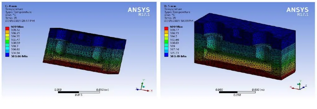
The study confirmed that as the coolant channel is moved further from the die base, the surface temperature increases. While the overall temperature variation was small, it was consistent. As noted in Figure 3.9 of the paper, the minimum temperature of 582.15°C was recorded at the 0.5 mm location, which steadily increased to 583.49°C at the 5 mm location. This establishes a clear link between cooling channel geometry and the thermal load experienced by the die surface.
Finding 2: The 1 mm Location Achieves Maximum Fatigue Life and Minimum Stress
The most critical finding of the study is the superior performance of the 1 mm coolant channel location. As detailed in Table 3.1, this specific geometry strikes an optimal balance between cooling efficiency and induced stress.
- At the 1 mm location, the die experienced a minimum normal stress of 241.56 MPa, resulting in a maximum fatigue life of 113,080 cycles.
- In contrast, the 0.5 mm location, despite being slightly cooler, induced a higher stress of 242.24 MPa and a lower life of 111,540 cycles.
- As the channel moved further away, from 2 mm to 5 mm, normal stresses increased and fatigue life dropped progressively, with the 5 mm location yielding the lowest life of just 95,820 cycles.
This demonstrates that there is a non-linear relationship between cooling proximity and die life. Being too close or too far from the surface is suboptimal. For the geometry tested, 1 mm proved to be the "sweet spot" for maximizing tool life.
Practical Implications for R&D and Operations
The findings from this paper offer valuable, data-backed insights for engineering and operational teams in the HPDC industry.
- For Process Engineers: This study suggests that adjusting the die's cooling parameters, specifically based on channel location, is a powerful tool for managing thermal fatigue. It reinforces that internal cooling is not just about removing heat, but about precisely controlling the thermal gradient to minimize stress and extend HPDC die life.
- For Quality Control Teams: The data in Table 3.1 illustrates the direct effect of thermal conditions on stress and expected life. This correlation can inform predictive maintenance schedules and help identify dies that may be at higher risk of premature failure based on their design.
- For Design Engineers: The findings provide a critical design principle: the placement of cooling channels is not arbitrary. The data strongly indicates that an optimized distance (identified as 1 mm in this specific model) can significantly influence thermal fatigue crack formation. This is a valuable consideration to implement during the initial die design phase to build longevity into the tool from the start.
Paper Details
Effect of Die Geometry on Fatigue Analysis of Aluminium Alloy (ADC12 Aluminium A383) using Pressure Die Casting Process
1. Overview:
- Title: Effect of Die Geometry on Fatigue Analysis of Aluminium Alloy (ADC12 Aluminium A383) using Pressure Die Casting Process
- Author: Poshan Dewangan, Ved Prakash Dewangan, Sushil Kumar Maurya, Lokesh Singh
- Year of publication: 2021
- Journal/academic society of publication: International Journal of Scientific Research in Civil Engineering (IJSRCE)
- Keywords: Aluminium Alloys, Die-Casting, Thermal Fatigue, Temperature Distribution, Life
2. Abstract:
Dies for aluminium alloys die-casting fail because of a great number of different and simultaneously operating factors. In the process of the die-casting the primary source of loading is cyclic variation of the temperature. For economical production of aluminium and aluminium alloys die castings it is important that the dies have a long working life. The main objective of this work is to find out the thermal fatigue of die casting Aluminium Alloy (A02240) which causes reduction in tool life and seriously affects the surface conditions. The size and location of cooling channels relative to the surface of the die affect the thermal stresses and fatigue life of dies. This work focuses on thermal fatigue analysis of Aluminium alloy pressure die casting process and analyses the effect of coolant channel location on temperature distribution and fatigue parameters such as life, damage, equivalent alternating stress and biaxiality using ANSYS Workbench 17.1 finite-element package.
3. Introduction:
Die casting is a cost-efficient method for forming thin-walled and complex near-net-shaped products. Low melting point alloys like aluminum are frequently used. Die casting tools are exposed to severe thermal, mechanical, and chemical conditions during each cycle. The service life of these tools is primarily limited by thermal fatigue cracking, erosion, and corrosion. Thermal fatigue cracking is particularly significant in aluminum alloy die casting due to the high temperature of the melt. This failure mode reduces the surface quality of castings and increases production costs due to tool maintenance and replacement. The overall aim of this work is to develop better tool materials and designs for die casting.
4. Summary of the study:
Background of the research topic:
The failure of dies in aluminum die casting is a major economic concern. The primary failure mechanism is thermal fatigue, caused by the cyclic heating and cooling of the die surface. This leads to crack formation, which compromises the quality of the cast parts and shortens the life of the expensive die.
Status of previous research:
Previous research has identified thermal fatigue as a critical issue. The thermal stresses that cause cracking develop from the thermal gradient across the die, which is a result of the heating and cooling stages of the casting cycle.
Purpose of the study:
The main objective was to analyze the effect of die geometry, specifically the location of cooling channels, on the thermal fatigue of a die used for casting Aluminium Alloy A02240. The study aimed to quantify the impact of coolant channel location on temperature distribution, thermal stress, and key fatigue parameters like die life and damage.
Core study:
The core of the study involved a transient thermal and structural analysis using ANSYS Workbench 17.1. A 3D model of a die was created, and simulations were run for six different coolant channel locations (0.5 mm to 5 mm from the base). The analysis evaluated the resulting temperature distribution, normal stress, fatigue life, fatigue damage, equivalent alternating stress, and biaxiality for each configuration to identify the optimal geometry.
5. Research Methodology
Research Design:
The study employed a comparative simulation-based research design. A single die geometry was modeled, and the location of the internal cooling channel was systematically varied. The performance of each configuration was then evaluated against key thermal fatigue metrics under identical simulated casting conditions.
Data Collection and Analysis Methods:
Data was generated using the ANSYS Workbench 17.1 finite-element analysis software. The software performed transient thermal analysis to determine temperature distribution over time, followed by a structural analysis to calculate stresses. Finally, a fatigue analysis was conducted to predict the life, damage, and other fatigue-related parameters based on the calculated stress cycles. The results were compiled and compared to identify trends and optimal conditions.
Research Topics and Scope:
The research was focused on the thermal fatigue analysis of an aluminum alloy (A02240/A383) pressure die casting process. The scope was limited to analyzing the effect of a single geometric parameter: the location of the coolant channel relative to the die's base. The analysis covered temperature distribution and fatigue parameters such as life, damage, and stress.
6. Key Results:
Key Results:
- The coolant channel located 1 mm from the base yielded the maximum fatigue life of 113,080 cycles.
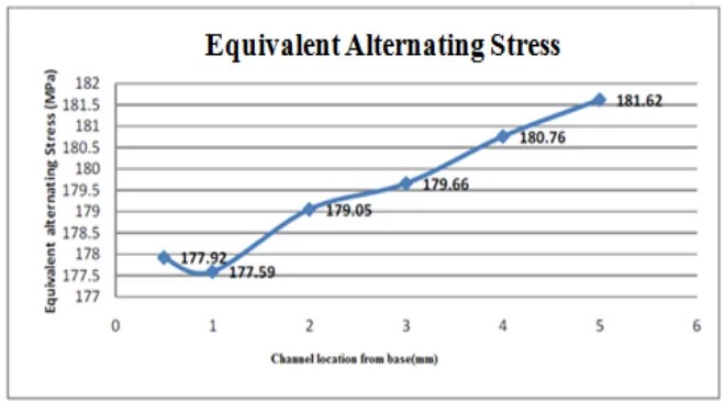
- The 1 mm location also corresponded to the minimum normal stress of 241.56 MPa and the minimum equivalent alternating stress of 177.59 MPa.
- Fatigue life decreased as the coolant channel was moved further from the 1 mm optimal position, dropping to 95,820 cycles at the 5 mm location.
- Die surface temperature showed a direct correlation with coolant channel distance, increasing from 582.15 °C at 0.5 mm to 583.49 °C at 5 mm.
Figure Name List:
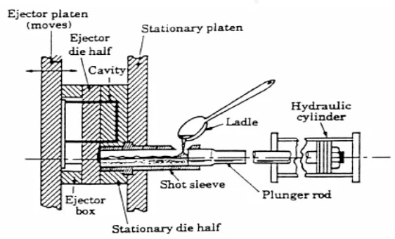
- Fig.1.1: Cold-chamber die casting
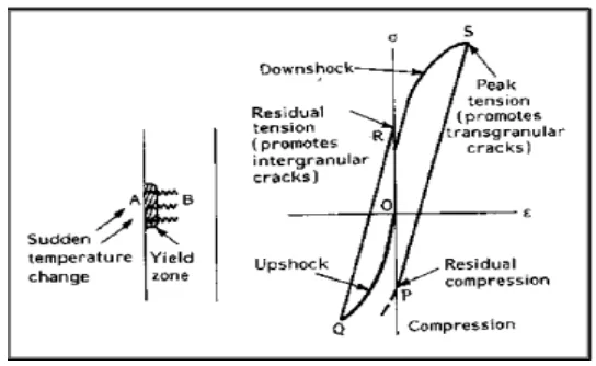
- Fig.1.2: Hysteresis loop at the surface of a material subjected to cyclic heating cooling
- Fig.3.1: Geometrical 3D CAD model
- Fig.3.2: Messing of Die Geometry
- Fig.3.3 (a) Temperature Distribution for 0.5 mm base location (b) Temperature Distribution for 1 mm base location
- Fig.3.4 (a) Temperature Distribution for 2 mm base location (b) Temperature Distribution for 3 mm base location
- Fig.3.5 (a) Temperature Distribution for 4 mm base location (b) Temperature Distribution for 5 mm base location
- Fig.3.6 (a) Fatigue Life for 0.5 mm base location (b) Fatigue Life for 1 mm base location
- Fig.3.7 (a) Fatigue Life for 2 mm base location (b) Fatigue Life for 3 mm base location
- Fig.3.8 (a) Fatigue Life for 4 mm base location (b) Fatigue Life for 5 mm base location
- Fig. 3.9: Temperature distribution for aluminium alloy
- Fig. 3.10: Fatigue life for aluminium alloy
- Fig. 3.11: Equivalent alternating stress for aluminium alloy


7. Conclusion:
The life of a high-pressure die casting die can be increased by using an effective cooling channel near the base. The results indicated that while a location of 0.5 mm from the base induces high stress, the coolant location at 1 mm from the base experiences a temperature of 582.18 °C, which corresponds to a minimum normal stress of 241.56 MPa and a fatigue life of 113,080 cycles. This was considered to be the best among the coolant channel locations tested.
8. References:
- [1]. JCollot et alReview of New Process Technologies in the Aluminum Die-Casting Industry Materials and Manufacturing Processes, 200116(5): p595-617.
- [2]. QHan, and SViswanathan, Analysis of the mechanism of die soldering in aluminium die castingMetallurgical and Materials ransactions, 200334(1): p139-146.
- [3]. ASrivastava, VJoshi and R Shivpuri; 2004; Computer modelling and prediction of thermal fatigue cracking in diecasting toolingIntJWear 256: 38-43.
- [4]. DSchwam, JFWallace and SBirceanu; 2004; Effect of design factors on thermal fatigue cracking of die casting diesDE-FC07-00ID138486,US Department of Energy, Washington, DC.
- [5]. DNovovic, RCDewes and DKAspinwall;2004; The effect of machined topography and integrity on fatigue lifeIntJMach Tools Manuf44 :125-134.
- [6]. MOkayasu; 2009; Comparison of mechanical properties of die cast aluminium alloys: cold vshot chamber die casting and high vslow speed filling die castingIntJCast MetRes22: 324-381.
- [7]. SAqida etal., Thermal fatigue properties of laser treated steelsInternational Journal of Material Forming, 20103(1): p797-800.
- [8]. J.J.Moverare,; DGustafsson Hold-time effect on the thermo-mechanical fatigue crack growth behaviour of inconel 718MaterSciEngA 2011, 528, 8660-8670.
- [9]. SChang, K.Huang, and YWang, Effects of thermal erosion and wear resistance on AISI H13 tool steel by various surface treatments Materials Transactions, 201253(4): p745-751.
- [10]. DKlob car.; LKosec; J.Tušek; Thermo fatigue cracking of die casting diesEngFailAnal2012, 20, 43-53.
- [11]. IKoutiri, et al., High cycle fatigue damage mechanisms in cast aluminium subject to complex loadsInternational Journal of Fatigue, 201347: p44-57.
- [12]. DMatiskova,.; SGaspar,.; LMura,Thermal factors of die casting and their impact on the service life of moulds and the quality of castingsActa Polytech Hung2013, 10, 65–78.
- [13]. DMatiskova,.; SGaspar,.; LMura,Thermal factors of die casting and their impact on the service life of moulds and the quality of castingsActa PolytechHung2013, 10, 65–78.
- [14]. Fazliana Fauzun, SNAqida, SNaher and DBrabazon;2014; effects of thermal fatigue on laser modified H13 Die Steel; Journal of mechanical engineering and sciences(JMES);ISSN:2289-4659; volume 6, pp975-980.
- [15]. Xu, W.; Li, W.; Wang, YExperimental and theoretical analysis of wear mechanism in hot-forging die and optimal design of die geometryWear 2014, 318, 78-88.
- [16]. Qian wan, Haidong Zhao and Chun Zou; 2014; effect of micro porosities on fatigue behavior in Aluminium die casting by 3D x-ray tomography inspection; doi.org/10.2355/isijinternatinal.
- [17]. OAmmar,; NHaddar,; LRemy, Numerical computation of crack growth of low cycle fatigue in the 3041 austenitic stainless steelEngFractMech2014, 120, 67-81.
- [18]. IVicario, JKIdoiaga, EArratibel and PCaballero;2015; Development of HPDC advanced dies by casting with reinforced tool steels; International Journal of manufacturing Engineering;doi.org/10.1155/2015/287986.
- [19]. CChen; YWang; Energy-based approach to thermal fatigue life of tool steels for die casting diesIntJFatigue 2016, 92, 166–178.
- [20]. Xu Li, Bao-sheng Liu, Li-feng Hou and Ying-hui Wei;2017; Failure investigation of an AlSi9Cu3 Alloy Die-Cast Cavity Insert; Journal of failure analysis and prevention; issue6.
- [21]. Ibrahim Ozbay, Tamer Aydiner, Gurkan Yilmazoglu and Hafize Celik;2019; Aluminium high pressure Die casting application on rear frame rails; European mechanical science; e-ISSN: 2587-1110.
- [22]. Federico Simone Gobber, Andrea Giuseppe Pisa and Mario Rosso;2019; design of a Test Rig for the characterization of thermal fatigue and soldering resistance of the surfaces of tool steels for high pressure die casting dies; Steel research International: doi.org/10.1002/srin.201900480.
Expert Q&A: Your Top Questions Answered
Q1: Why was a finite-element analysis (FEA) using ANSYS chosen for this study instead of physical experimentation?
A1: The paper opted for an FEA simulation because it allows for precise control and isolation of variables, which can be difficult and expensive in a physical production environment. Using ANSYS Workbench 17.1, the researchers could systematically change the single geometric parameter of coolant channel location and accurately measure its impact on temperature, stress, and fatigue life. This approach provides clear, comparative data that is essential for optimizing design principles.
Q2: The temperature difference between the best (1 mm) and worst (5 mm) performing locations is less than 1.5°C. Why does such a small temperature change lead to a ~15% difference in fatigue life?
A2: This highlights a key principle of thermal fatigue. While the peak temperature difference is small, fatigue life is primarily driven by the magnitude of the cyclic stress, not just the temperature itself. The data in Table 3.1 shows that the 1 mm location results in the lowest normal stress (241.56 MPa). The relationship between stress and fatigue life is typically logarithmic (as seen in S-N curves), meaning even small reductions in cyclic stress can yield significant increases in the number of cycles to failure.
Q3: What is the practical meaning of the "Fatigue Damage" value in Table 3.1?
A3: As explained in section 4.3 of the paper, fatigue damage is a calculated value defined as the design life divided by the available (predicted) life. Therefore, a lower fatigue damage value indicates a longer available life and better performance. The 1 mm location had the lowest damage value (8843.1), which corresponds directly to its highest predicted fatigue life (113,080 cycles), confirming it as the most durable configuration.
Q4: Does this study imply that a 1 mm coolant channel distance is the universal optimum for all aluminum HPDC dies?
A4: Not necessarily. The conclusion explicitly states that the 1 mm location was "the best among the coolant channel locations" tested for the specific die geometry in this study. The critical takeaway for the industry is the principle itself: that an optimal distance exists and must be determined. For a different die with more complex geometry, thicker walls, or different heat-sinking characteristics, the exact optimal distance might be different, but the methodology used here provides a clear roadmap for finding it.
Q5: The paper mentions "Biaxiality Indication." What is its significance in this analysis?
A5: Biaxiality indication describes the nature of the stress state on the die surface. A value of 1 corresponds to a pure biaxial state (stress acting equally in two perpendicular directions), which is typical for a surface being heated and cooled that is constrained from expanding freely. The values in Table 3.1 are all very close to 1 (e.g., 0.99889 for the 1 mm location), which validates that the simulation is accurately modeling the type of thermal stress that causes heat checking and fatigue cracking in real-world dies.
Conclusion: Paving the Way for Higher Quality and Productivity
This research effectively demonstrates that mitigating thermal fatigue—a primary enemy of tool longevity—is an achievable engineering goal. By moving beyond a one-size-fits-all approach to cooling, die designers can unlock significant improvements in performance. The key finding—that an optimized coolant channel location of 1 mm from the base maximized fatigue life for this specific geometry—provides a powerful data point for the industry. This strategic design choice directly contributes to extending HPDC Die Life, reducing tooling costs, and improving the consistency of cast part quality.
At CASTMAN, we are committed to applying the latest industry research to help our customers achieve higher productivity and quality. If the challenges discussed in this paper align with your operational goals, contact our engineering team to explore how these principles can be implemented in your components.
Copyright Information
- This content is a summary and analysis based on the paper "Effect of Die Geometry on Fatigue Analysis of Aluminium Alloy (ADC12 Aluminium A383) using Pressure Die Casting Process" by "Poshan Dewangan, Ved Prakash Dewangan, Sushil Kumar Maurya, Lokesh Singh".
- Source: https://ijsrce.com/IJSRCE21528
This material is for informational purposes only. Unauthorized commercial use is prohibited.
Copyright © 2025 CASTMAN. All rights reserved.