This introductory paper is the research content of the paper ["Development of water-based core technology for light alloys"] published by [University of Teesside].
1. Overview:
- Title: Development of water-based core technology for light alloys
- Author: Manu Ramegowda
- Publication Year: August 2008
- Publishing Journal/Academic Society: Unpublished PhD Thesis. University of Teesside.
- Keywords: water-based core technology, light alloys, fused silica, plaster, magnesium oxide, leaching
2. Abstracts / Introduction
ABSTRACT
This thesis describes, in a manufacturing context, the development of new water based core technology for light alloys.
Cores used for steel casting are made from fused silica and are removed using hot sodium hydroxide under refluxing (pressurising hot acids). However, aluminium and other light alloys are attacked by sodium hydroxide. Currently there is no good core system for aluminium and other light alloys. It is therefore desirable to find an alternative material/leaching agent combination for casting aluminium and other light alloys.
The recent research review has shown that ceramic cores are mostly made by fused silica with different additives. The previous research has suggested using fused silica (different mesh size) as filling material and using magnesium oxide to control the slurry working life of core mixes. Calcium silicate assists core leaching in dilute acid. The plaster (calcium sulphate) in the form of proprietary plasters (Crystcal R, Fine Casting Plaster) is used to create bond and gives strength to the core. Lithium carbonate acts has an accelerator, improving the strengthening effect of the plaster in the cores. The binder (Ludox® AM) and water act (as added materials) to bind the composition
Core compositions were made with different core trials to produce a core, which records suitable strength and quick leaching properties for light alloys. Core trials were individually mixed and poured into a wooden core box. Cores were pre-dried for twenty-four hours. Cores were fired to different temperatures for two hours, followed by two hours cooling. The cores were subjected to computerised three-point bend test to record the Modulus of rupture (MOR). The plain strain fracture toughness and Weibull parameters were calculated. The Weibull parameter was plotted using Minitab analysis software. Using the cores, gravity die casting process were carried out. The subsequent castings was dipped in diluted nitric, citric and acetic acid to leach out the core.
Using different core compositions, core trials were mixed, poured, dried, tested and leached. The high amount of plaster in core trials records high MOR when cores were fired between 200°- 400° C and the opposite result when fired between 600°- 800° C. The different grade of plasters(CRP,FCP) do not influence the strength. One percent of magnesium oxide gives a very short working life. High amount of binder(Ludox® AM) in core produce strong cores.
Workable MOR results can be obtained depending on composition allowing manual handling or a waxing process. The fracture toughness is typical of a brittle material, with matching Weibull parameters. The casting process suggests that the new materials are sufficiently refractory. The cores are leached out using diluted nitric, acetic and citric acid at rates compatible with commercial manufacture.
This methodology has successfully produced a core using fused silica with plaster and magnesium oxide for aluminium and possibly for light alloys. Different core trials can be used depending on the specific industrial application relating to strength and removal with acid attacking the metal. Further work is needed to fine tune optimum leaching conditions.
3. Research Background:
Background of the Research Topic:
Cores are essential components in metal casting, used to create internal features in castings. Traditionally, cores for steel casting are made of fused silica and removed using hot sodium hydroxide. However, this method is unsuitable for aluminium and light alloys because sodium hydroxide attacks these metals. Therefore, the development of an alternative core technology for light alloys is needed.
Status of Existing Research:
Previous research indicates that ceramic cores are primarily made of fused silica with additives. Fused silica of different mesh sizes is used as a filler, and magnesium oxide is used to control the slurry working life. Calcium silicate aids core leaching in dilute acid. Plaster (calcium sulphate), in forms like Crystcal R and Fine Casting Plaster, is used as a binder to provide strength. Lithium carbonate is used as an accelerator to enhance plaster strengthening. Ludox® AM binder and water are also used in core compositions.
Necessity of the Research:
Currently, there is no optimal core system for aluminium and other light alloys. Existing methods using sodium hydroxide are not applicable due to the corrosive nature of sodium hydroxide to these alloys. An alternative material and leaching agent combination is required to facilitate the casting of aluminium and light alloys. This research aims to address this gap by developing a water-based core technology suitable for light alloys, using less aggressive leaching agents like dilute acetic acid, offering environmental benefits and solving waste disposal issues associated with caustic soda.
4. Research Purpose and Research Questions:
Research Purpose:
The project aims to develop a water-based core technology for light alloys, modifying existing compositions to enable core removal using less aggressive leaching agents than caustic soda, such as dilute acetic acid. The research seeks to optimize core composition for dimensional stability, strength, mechanical properties, and easy removal with environmentally friendly reagents. The ultimate goal is to evaluate the suitability of the developed core as a casting core.
Key Research:
- Development of new water-based core technology for light alloys.
- Finding an alternative material/leaching agent combination for casting aluminium and other light alloys.
- Modifying core composition for removal from aluminium and alloy castings using less aggressive leaching agents like dilute acetic acids.
- Determining the optimum core composition for dimensional stability, strength, and other mechanical properties.
- Evaluating the suitability of the developed core as a casting core.
5. Research Methodology
Research Design:
The research employed an iterative experimental approach, starting with initial core compositions and systematically varying components to optimize mechanical properties, casting performance, and core removal. Different core compositions were formulated and tested, with trials designed to assess the impact of varying plaster, binder, and magnesium oxide percentages, as well as the use of calcium silicate and different plaster types.
Data Collection Method:
- Core Preparation: Core compositions were mixed, poured into wooden core boxes, pre-dried, and fired at different temperatures (200°C, 400°C, 600°C, 800°C).
- Mechanical Testing: Computerized three-point bend tests were conducted to measure Modulus of Rupture (MOR). Plain strain fracture toughness and Weibull parameters were also calculated.
- Core Removal Testing: Gravity die castings were made using the cores and subsequently leached in diluted nitric, citric, and acetic acid solutions of varying concentrations and durations. The ease of core removal was assessed visually and through probing.
- Dimensional Measurement: Core dimensions (diameter and length) were measured before and after firing to evaluate shrinkage.
- Microscopy: Scanning electron microscopy (SEM) was used to examine the surface morphology of selected core samples.
Analysis Method:
- Modulus of Rupture (MOR) Analysis: MOR values were calculated from three-point bend test data to assess core strength.
- Weibull Analysis: Weibull parameters were calculated and plotted using Minitab software to analyze the reliability and variability of core strength.
- Fracture Toughness Analysis: Plain strain fracture toughness (KIC) was calculated to evaluate the material's resistance to brittle fracture.
- Statistical Analysis: Minitab software was used for statistical analysis, including distribution overview plots and Weibull analysis.
- Qualitative Analysis: Visual inspection and probing were used to assess core removal effectiveness and core defects.
Research Subjects and Scope:
The research focused on developing water-based core technology for light alloys, specifically aluminium. The core materials investigated included fused silica, plaster (various types), magnesium oxide, lithium carbonate, calcium silicate, tri-sodium citrate, and Ludox® AM binder. Core compositions were tested for mechanical properties, casting performance in gravity die casting, and removal using diluted acids. The scope was limited to laboratory-scale experiments and did not extend to full-scale industrial trials.
6. Main Research Results:
Key Research Results:
- Core Composition and MOR: High plaster content in core trials resulted in high MOR when fired at 200°-400°C, but the opposite occurred at 600°-800°C. Different plaster grades (CRP, FCP) did not significantly affect strength. High binder content (Ludox® AM) produced strong cores.
- Slurry Working Life: One percent magnesium oxide led to a very short slurry working life.
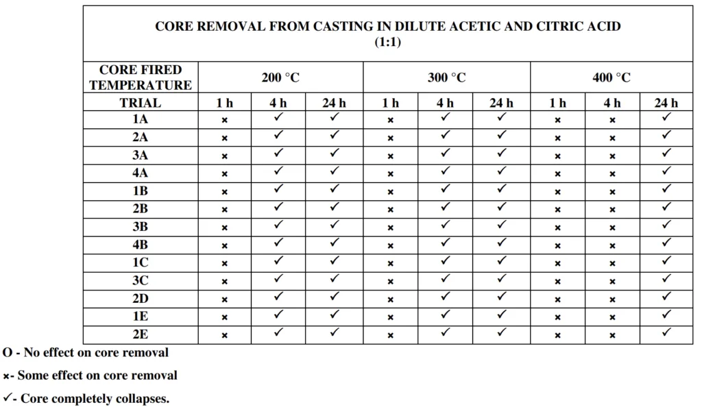
- Leaching: Diluted nitric, citric, and acetic acids successfully leached out cores at rates compatible with commercial manufacturing. Higher concentrations of nitric acid (1:1, 1:2, 1:5) were more effective in leaching cores, but diluted acetic and citric acids also showed promising leaching capabilities, especially at higher concentrations (1:100 for acetic acid and 1:100 for citric acid).
- Dimensional Stability: Finer mesh size fused silica (-200) improved dimensional stability and reduced shrinkage compared to coarser fused silica.
- Weibull Analysis: Weibull analysis indicated the brittle nature of the cores, with Weibull modulus values suggesting variability in strength.
- Fracture Toughness: Fracture toughness (KIC) values were calculated, providing insights into the material's resistance to crack propagation.
Analysis of presented data:
- MOR Variation with Temperature: MOR values generally decreased at higher firing temperatures (600°-800°C) for most core compositions, particularly those with higher plaster content, likely due to plaster decomposition and bond weakening at elevated temperatures.
- Effect of Magnesium Oxide: Magnesium oxide significantly reduced slurry working life, highlighting its role in accelerating the setting process.
- Leaching Effectiveness: Diluted nitric acid was generally more effective in leaching cores compared to citric and acetic acids, but all three acids showed leaching potential, especially at higher concentrations. The effectiveness varied with core composition and firing temperature.
- Dimensional Changes: Finer fused silica and specific core compositions (e.g., Trial D) exhibited better dimensional stability and reduced shrinkage.
- Weibull and Fracture Toughness: Weibull analysis confirmed the brittle nature of the cores, and fracture toughness values provided quantitative measures of their resistance to fracture.
Figure Name List:
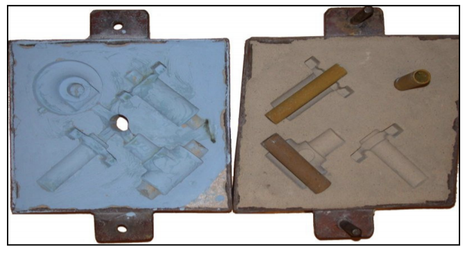
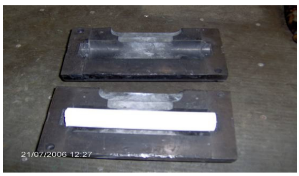
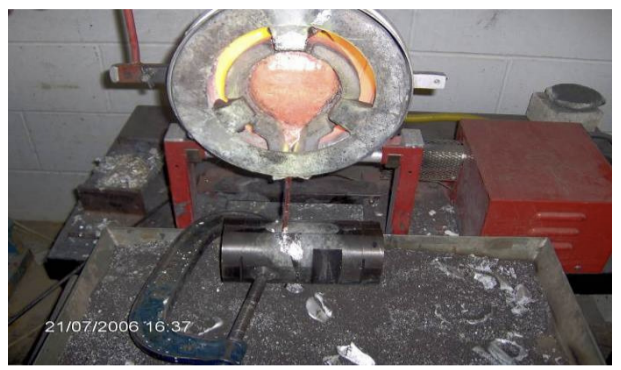
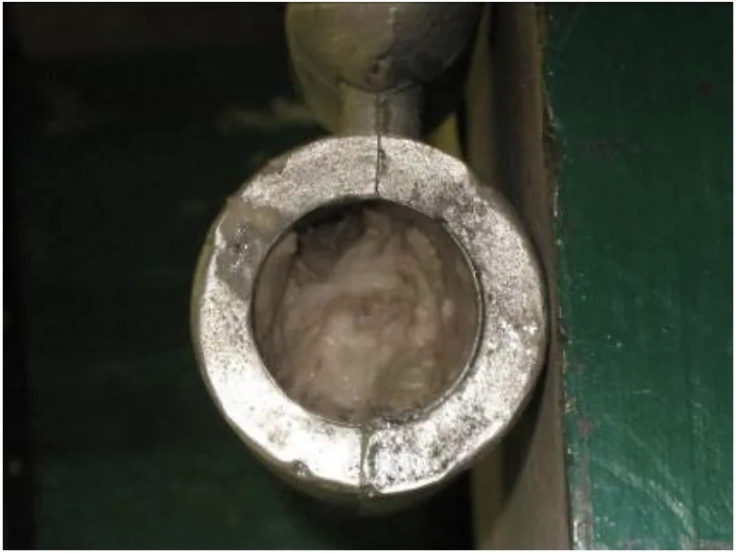
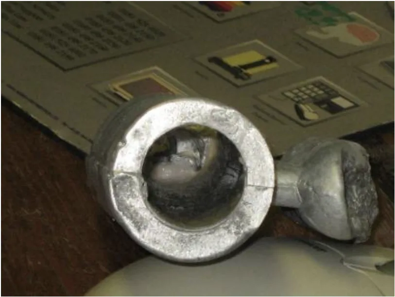
- Figure 1. Example of a complex sand core (9)
- Figure 2. Examples of different ceramic core shapes (10)
- Figure 3. Preformed core for an racing car exhaust component (10)
- Figure 4. Core being inserted into drag after curing (11)
- Figure 5. Conveyor core drying furnace (13)
- Figure 6.The three point loading scheme (35)
- Figure 7. Sand casting with sand cores (59)
- Figure 8. (a) Core blow (b) Defect caused by gas from cores before solidification (54)
- Figure 9. Core mould boxes with cores
- Figure 10. LLOYD Universal test machine
- Figure 11. Fracture sample with three point bend load
- Figure 12. Cast iron split moulds with core
- Figure 13. Pouring process to assembled mould
- Figure 14. General arrangement of cast iron mould
- Figure 15. Marked cast parts
- Figure 16. Cores left to dry
- Figure 17. Mean slurry working life at core trials
- Figure 18. Mean setting time at core trials
- Figure 19. The 24 hours firing with weight loss on core trials at 200 °C
- Figure 20. The 24 hours firing with weight loss on core trials at 400 °C
- Figure 21. Mean MOR of Trial A at different fired temperatures
- Figure 22. Mean MOR of Trial B at different fired temperatures
- Figure 23. Mean MOR of Trial C at different fired temperatures
- Figure 24. Mean MOR of Trial D at different fired temperatures
- Figure 25. Mean MOR of Trial E at different fired temperatures
- Figure 26. Effect of diluted nitric acid on Trial 1E core fired at 400 °C under four hours.
- Figure 27. Mean MOR in Trial A at different fired temperatures
- Figure 28. Core blow defect on the sectioned Al-LM25 (core removed)
- Figure 29. Vertical standing wooden core boxes with cores
- Figure 30. Cores fired at 600 °C with the 30/50 fused silica settled in the bottom.
- Figure 31. Mean setting time of core trials
- Figure 32. Mean slurry working life in Trial 4A at different percentages of MgO
- Figure 33. Mean MOR of Trial A at different fired temperatures
- Figure 34. Mean MOR of Trial B at different fired temperatures
- Figure 35. Mean MOR of Trial C at different fired temperatures
- Figure 36. Mean MOR of Trial D at different fired temperatures
- Figure 37. Mean MOR of Trial E at different fired temperatures
- Figure 38. Effect of dilute nitric acid (1:1, 1:2 and1:5) on Trial 1B fired at 200 °C after one hour
- Figure 39. Effect of dilute nitric acid (1:1, 1:2 and 1:5) on Trial 1B fired at 200 °C after four hours
- Figure 40. Mean MOR in Trial A at different fired temperature
- Figure 41. Al-LM25 break since not feeding the metal properly
- Figure 42. Mean setting time for core trials
- Figure 43. Mean MOR of Trial A at different fired temperatures
- Figure 44. Mean MOR of Trial B at different fired temperatures
- Figure 45. Mean MOR of Trial C at different fired temperatures
- Figure 46. Mean MOR of Trial D at different fired temperatures
- Figure 47. Mean MOR of Trial E at different fired temperatures
- Figure 48. Trial 4A core surface with Fused silica mesh size ( -200/-120) fired at 200 °C.
- Figure 49. Trial 4A core surface with Fused silica mesh size (-120/30-50) fired at 200 °C.
- Figure 50. Al-LM25 attacked by dilute potassium hydroxide.
- Figure 51. Trial 1B core leached by dilute citric acid (1:1) at 200 °C.
- Figure 52. Mean setting time of core trials
- Figure 53. Mean percentage length contraction of Trial A at different fired temperature
- Figure 54. Mean percentage length contraction of Trial B at different fired temperatures
- Figure 55. Mean percentage length contraction of Trial D at different fired temperatures
- Figure 56. Mean percentage length contraction of Trial E at different fired temperatures
- Figure 57. Mean diameter shrinkage percentage of Trial A at different fired temperatures
- Figure 58. Mean diameter shrinkage percentage of Trial B at different fired temperatures
- Figure 59. Mean diameter shrinkage percentage of Trial D at different fired temperatures
- Figure 60. Mean diameter shrinkage percentage of Trial E at different fired temperatures
- Figure 61. Mean MOR of Trial A at different fired temperatures
- Figure 62. Mean MOR of Trial B at different fired temperatures
- Figure 63. Mean MOR of Trial D at different fired temperatures
- Figure 64. Mean MOR of Trial E at different fired temperatures
- Figure 65. Mean setting time of core trials
- Figure 66. Mean percentage length contraction of Trial A at different fired temperatures
- Figure 67. Mean percentage length contraction of Trial 2D at different fired temperatures
- Figure 68. Mean percentage length contraction of Trial E at different fired temperatures
- Figure 69. Mean diameter shrinkage percentage of Trial A at different fired temperatures
- Figure 70. Mean diameter shrinkage percentage of Trial 2D at different fired temperatures
- Figure 71. Mean diameter shrinkage percentage of Trial E at different fired temperatures
- Figure 72. Mean MOR of Trial A at different fired temperatures
- Figure 73. Mean MOR of Trial 2D at different fired temperatures
- Figure 74. Mean MOR of Trial E at different fired temperatures
- Figure 75. Distribution overview plot for Trial A at 600 °C
- Figure 76. Distribution overview plot for Trial E and 2D at 600 °C
- Figure 77. Distribution overview plot for Trial A at 800 °C
- Figure 78. Distribution overview plot for Trial E and 2D at 800 °C
- Figure 79. (a) Crack on notched core Trial 3A at 800 °C, (b) Crack on notch core Trial 3A at 600 °C.
- Figure 80. Mean setting time for core trial
- Figure 81. Mean MOR for core composition [6] at different fired temperatures
- Figure 82. Mean MOR for core composition [7] at different fired temperatures
- Figure 83. Mean setting time for core composition [8] and [9]
- Figure 84. Mean MOR for core composition [8] at different fired temperatures
- Figure 85. Mean MOR for core composition [9] at different fired temperatures
7. Conclusion:
Summary of Key Findings:
This research successfully developed a water-based core technology for light alloys using fused silica, plaster, and magnesium oxide. The study demonstrated the feasibility of using diluted nitric, citric, and acetic acids for core removal, offering a less aggressive alternative to sodium hydroxide. Key findings include the influence of core composition on MOR, slurry working life, and leaching properties. Finer fused silica particles improved core strength and surface finish. The optimal core composition depends on specific application requirements, balancing strength, leaching efficiency, and dimensional stability.
Academic Significance of the Study:
This study contributes to the scientific understanding of water-based core technology for light alloys. It provides valuable data on the effects of different core compositions and firing temperatures on core properties, including MOR, fracture toughness, and leaching behavior. The research also advances the application of Weibull analysis in characterizing the reliability of ceramic cores.
Practical Implications:
The developed water-based core technology offers a practical solution for casting aluminium and light alloys, addressing the limitations of existing core systems. The use of diluted citric and acetic acids as leaching agents presents an environmentally friendlier alternative to caustic soda. The findings provide guidance for foundries in selecting appropriate core compositions and leaching methods based on specific casting requirements and industrial applications.
Limitations of the Study and Areas for Future Research:
This study was conducted at a laboratory scale, and further research is needed to validate the technology in industrial settings. The research suggests several areas for future work:
- Porosity and Density Analysis: Investigating the porosity and density of cores and their impact on leaching rates.
- Phase Change Analysis: Analyzing phase changes in core materials at elevated temperatures to optimize firing cycles.
- Commercial Production and Testing: Scaling up production and testing core compositions [4] and [5] in commercial casting environments with different low melting alloys.
- Finer Fused Silica Flour: Exploring the use of finer flour-grade fused silica to further improve core finish, strength, and leaching.
- Creep Characteristics: Investigating creep behavior at elevated temperatures to understand stress deformation and long-term performance.
- Binder Grade Variations: Examining the effects of different binder grades (Ludox HS and SK) on core properties.
- Injection Process Optimization: Exploring injection processes for mixed slurry to achieve higher particle packing and MOR.
8. References:
- [1. CAD Casting: Direct Fabrication of Ceramic Shells and Cores by Three Dimensional Printing, Sachs E B, Curodeau A D, Manufacturing Review (USA). Volume 5, p117-126, June 1992.]
- [2. Ceramic slurry composition for ceramic core of a dental prosthesis, Kim J D, Lee M H, Korean Science Technology, US patent 5975905, November 1999.]
- [3. Moulded ceramic cores for the production of precision cast impellers by the unicast process, Greenwood R E, Precision casting supplements, Foundry trade journal, p178-182, March 1984.]
- [4. Elements of material science and engineering, Van Vlack L H, Third edition, Addison- Wesley Publishing Company, 1975.]
- [5. Ceramic cores in the sand foundry, Greenwood R E, Cast metal times, p11-12, April 2002.]
- [6. Casting solutions Ltd, Robson B, Ceramic core and mould expert, Sheffield, February 2004.]
- [7. Principles of foundry technology, Jain P L, Second edtion, Tata McGraw Hill, 1996.]
- [8. Ferrous foundry-man’s handbook, Brown J, Elsevier, p18-20, July 2000.]
- [9. www.eos-gmbh.de/030356_appl_cm06.htm, 18 September 2006.]
- [10. http://www.core-tech-inc.com/form_ground.html, 18 September 2006.]
- [11. Properties of ceramic cores, Mills D, The British investment casters technical association, Fifteenth annual conference, 1980.]
- [12. Principle of metal casting, Heine R W, Loper C R, Philip C, Second edition, Tata McGraw-Hill, New Delhi,p121-175, 1976.]
- [13. http://www.enercombustion.com/EnServices.htm,19 September 2006.]
- [14. Methods of firing core, Altoonian M A, Runions R D, US patent 6403020-B1, p1-7, June 2002.]
- [15. Ceramic core; Nucleus for precision internal section, Greenwood R E, Unicast development corporation, Modern technology, p29-31, 1985.]
- [16. Alumina-based ceramics for core materials, Greskovich C D, US patent 4156614, GE company, p1-4, October 1977.]
- [17. Low temperature co-fired ceramic with improved registration, Shepherd P N, US patent 6560860-B2, CTS Corporation, p 1-6, January 2001.]
- [18. Injection molding of ceramic components provides flexibility in metal casting and forming, Uram S, Industrial heating, p42-43, 1987.]
- [19. Multipiece core assembly for cast airfoil, Sikkenga W E, Grumm A W, Howmet research corporation, US patent 6347660, February 2002.]
- [20. The effect of cristobalite seed on the crystallization of fused silica based ceramic core- A kinetic study, Wang L Y, ceramic international, p187-193, 1995.]
- [21. Printed materials on manufacturing fused silica, Minco Company, Midway, TN, USA, 2004.]
- [22. Dimensional changes and creep of silica core ceramics used in investment casting of supper alloys, Wereszczak A A, Breder K, Journal of material science, p 4235-4245, April 2002.]
- [23. Alumina core having a high degree of porosity and crushability characteristics, Klung F J, US patent 4164424, GE company, p1-12, August 1979.]
- [24. Basic inorganic chemistry, Cotton A, Gaus P L, Third Edition, Wiley J &sons Inc, p307-208, 1995.]
- [25. Printed material for calcium silicate and Lithium carbonate, Material safety data sheet, Sigma Aldrich Company, Pool,Doorset, UK, 2002.]
- [26. A textbook of quantitative inorganic analysis, Vogel A I, Second edition, Longmans, s1939.]
- [27. BPB gypsum special plasters, Data sheets on plasters, BS EN 9002:1994.]
- [28. Printed material data sheet for tri-sodium citrate, University of Teesside Chemistry online database, 2005.]
- [29. CRC handbook of chemistry and physics, Forty fourth edition, p2292.]
- [30. Ludox AM®, Colloidal silica data sheet, Grace division , Grace W R & Co, Worms, Germany, 2006.]
- [31. Water Soluble cores and methods for manufacturing cast rotor, Aiga T, Toshiaki M, US patent 4438804, March1984.]
- [32. Basic inorganic chemistry, Cotton A, Gaus P L, Third edition, Wiley J &sons Inc, p231-232, 1995.]
- [33. Inorganic Chemistry , An Intermediate Text, Wood C W, Holliday A K, Third Edition, Butterworth’s, 1967,p165-166.]
- [34. Standard test method for flexural strength of advanced ceramics at ambient temperature, ASTM Standard C1161.]
- [35. Materials handbook, Brady G S, Clauser H R, Vaccari J A, fifteenth edition, McGraw-Hill, 2002.]
- [36. http://www.qualitydigest.com/jan99/html/body_weibull.html,19 September 2007.]
- [37. Interpret the shape, scale, and threshold on a Weibull probability plot, ID766, Minitab help handbook.]
- [38. Weibull Analysis, Weibull W, Journal of applied mechanics, p293-297, 1951.]
- [39. Engineering materials 2, Ashby M F, Jones D R H, Third edition, Elsevier Publications, p196-197, 2006.]
- [40. Strength, fracture toughness and microstructure of a selection of all ceramic materials, Ringer S P, Swain M V, Dental materials, p441-448, June2004.]
- [41. Fracture toughness comparison of three test methods with four dental porcelains, Wang H, Pallav P, Dental materials, p905-910, July2007.]
- [42. Engineering Materials 2 , Ashby M F, Jones D R H, Third edition, Elsevier Publications, p198-199, 2006.]
- [43. Aluminum alloys- structures and properties, Mondolfo L f, Butterworths London and Boston, p971, 1976.]
- [44. Aluminum LM25 data sheet, MRT casting limited, Foundries and machinist for non-ferrous cast parts, www.mrt-castings.co.uk., 20th September 2007.]
- [45. Commonly used magnesium alloy has a chemical composition including aluminium, zinc, manganese, copper, silicon, iron and nickel.]
- [46. Copper and its alloys were among the earliest metallic objects made from molten metal. Since copper was found as native metal, it has been worked into artifacts. The main bulk of copper production comes from ores, which are primarily mined for their copper content. The principal alloying elements include nickel, zinc, and combinations of different metals. The melting point of copper and its alloys with gold, tin, and zinc are low enough to be within the range of temperatures, which can be reached by wood and charcoal fires.]
- [47. Copper casting alloys are specified for services where superior corrosion resistance, electrical conductivity, good bearing surface qualities, and other special properties are desired. The tolerance for impurities is normally greater in castings than in their wrought copper because of the adverse effect on hot or cold workability.]
- [48. Table 17. Comparisons of different aluminium casting processes (48)]
- [49. Pressure Die Casting, the fastest of all casting processes, ranks and competes with stamping, die forging, plastic injection moulding where large numbers of identical parts are required. The molten metal is forced into the mould cavity under high pressure. The hot (metal flows into chamber) and cold chambers are the two type of machine principles used in pressure die-casting. The metal enters the die through the gate in a high velocity jet, the dimensions and velocity of which depend upon the dimensions of the gate and runner. This jet strikes the opposite face of the die cavity and spreads out in all directions filling the die cavity rapidly and breaking down into turbulent flow as the cavity fills up. Solidification takes place under pressure. The die itself is normally machined from a steel forging, spark erosion methods being used for intricate cavities.]
- [50. Aluminium, magnesium, copper-base and other high melting alloys use cold chamber principle (metal is ladled into chamber). The use of pressure die-castings reduces the time (assembly) and expense (tooling) required producing the product.]
- [51. Sand Casting is a means of producing rough metal castings using a mould made from sand formed around a replica of the object to be cast that is removed once the sand has been compacted. Medium sized “green” sand moulds are enclosed in flasks that consist of two parts, upper part (cope) and lower part (drag). The shapes of the desired casting are simulated by a pattern around which the moulding sand is formed. The patterns are made of wood or metal, also in two parts that can be fitted together. The green sand is rammed around one-half of pattern placed in the drag. The same process is carried out in the cope with spurs (runner) and gates (risers).]
- [52. When sand casting aluminium alloy, gas content and grain refinement are the two special points that must be taken into consideration. Gas content should be controlled at a reasonably low level to avoid the formation of blowholes and porosity. De-gassing tablets (hexachlorethane) are used to control the gas content. In slowly cooled castings there may be a tendency for large crystals to form, leading to reduced mechanical properties. Addition of titanium and boron can prevent the grain refinement in aluminium alloy sand casting .]
- [53. The form and position of defects in castings is often of greater importance than the size. A large pore in a low stressed area of the casting may be far less detrimental than a small “bifilm” in a sharp corner subject to a high tensile stress . Fins or flashing can occur if a die is worn or not clamped tight. It may also result in run-outs. Cast part]
- [54. Figure 8. (a) Core blow (b) Defect caused by gas from cores before solidification (54)]
- [55. In 1974, the British Cast Iron Research Association (BCIRA) reported loosening CO2 core sand in the internal passage of heavily cored castings using “lithotripsy”. Metal core boxes are preferred where cores are to be mass-produced or a more durable containment is required.]
- [56. There have been other attempts to use mechanical energy to remove cores involving ultrasonic vibration. Initial trials were made to use ultrasonic vibration alone to remove cores from turbine blades. This evolved into the use of ultrasonic waves generated and propagated through hot caustic alkalis in which the castings were immersed, to combine mechanical and chemical core removal techniques.]
- [57. Electrical energy, generated from a large capacitor bank, can be also be focused. The intensity of the pressure waves transmitted to the part from the shock wave in the water depends on the acoustic impedance of the ceramic core itself, so it is necessary to know the strength of the materials used in ceramic cores.]
- [58. A stream of water is focused on the core under great pressure and the core is progressively washed out. This procedure takes place in a purpose built facility or blasting room. “Cerabite” is an example of a typical commercial process .]
- [59. Figure 7. Sand casting with sand cores (59)]
- [60. The use of finer particles of fused silica improved the mix and produced a smooth flowing, easy pouring slurry, with acceptable setting and removal from the wooden core box. Since these cores are poured cores, the overall mean strength is less than the pre-formed cores, which are made by injecting the mixed slurry into core boxes under pressure.]
- [61. WATER is not usually thought of as a binder. Unless an optimum percentage of water exists in the core mixture, binders and additive do not function properly. Failure to use enough water results in not developing green strength from “cereals” and poor scratch hardness, low tensile strength after firing. This factor makes the water molecule a strong proton acceptor.]
- [62. The MOR variations of cores when fired at different temperatures are expected, since adding different materials to dental plaster and water disturbs the strength and balance of its composition .]
- [63. Adding a high percentage of binder to the ceramic raw materials makes the slurry flow very smooth and slow.]
- [64. Using magnesium oxide makes the mixed slurry set very quickly. With colloidal silica, it forms a ceramic slurry that can readily set in hot water within four to ten minutes.]
- [65. The introduction of ceramic cores has benefited sand foundries with smooth precision internal cavities at competitive costs and reduced time. Researchers elsewhere examined six different silica cores fired at 1530 - 1600 °C and held at maximum temperature for ten to thirty minutes prior to cooling to room temperature.]
- [66. A ceramic core system for such light alloys. The ceramic cores that have one firing cycle are mostly fired above 1300 °C. The higher temperature confirms the smaller dimensional change and hardening of the ceramic material.]
- [67. For a plate of semi-infinite width containing single centre or edge crack of a length, Y (a/W) is 1.1. The KIC values for ceramic materials are smaller than for metals, typically smaller than 10 MN √m. Normally, ceramics have a low linear co-efficient of thermal expansion. The strong interatomic bonding forces found in ceramic materials give a value for the coefficient of thermal expansion in a range between 0.5-15 × 10-6 (per °C).]
- [68. Magnesium oxide and calcium phosphates cores were used to cast superalloys in an effort to avoid the use of silica based cores, these being difficult to leach using a non-corrosive leaching medium.]
- [69. A 75% magnesium oxide and 25% magnesium chloride mixture was used to form a slurry.]
- [70. For light metals and superalloys, diluted nitric acid and bases such as potassium hydroxide are used. The mean setting time of core trials were ideal for any commercial application, with the exception of that in Trial C.]
- [71. The leaching rate is about 10 mm/h with 20-25% of density .]
- [72. With calcium silicate, sodium chloride, potassium chloride and sodium metasilicate is added to produce a core.]
- [73. The “greencast” process is a new lost-core technology for the production of hollow parts from thermoplastics and thermosets using water-soluble cores.]
- [74. Acids are substances that can denote hydrogen ions to bases (proton accetors).]
- [75. Ceramic cores produced with silica material with an addition of 0.05% of MgO gave 2% shrinkage with synthetic amorphous silica (binder). The amount of core shrinkage varies directly with the percentage of synthetic amorphous silica in the core material slurry.]
- [76. Ceramic cores produced with silica (17%), zircon, (30%) and binder (colloidal silica gel) have 0.5% of shrinkage in dimensions.]
- [77. Table 3. Properties of Fused silica (77)]
- [78. The plain strain fracture toughness of advance ceramics can be as low as 3 MN m-3/2 and as high as 12 MN m-3/2.]
- [79. To calculate the ‘Y’ for a circular section with a semi-circular notch on three points bending a closed form solution was developed .]
- [80. If the crack or notch is having a cutting edge (sharp), the degree of stress concentration is lower and may give spurious values. ]
- [81. Sodium hydrogen phosphate was used as binder.]
- [82. Lithium carbonate is an important industrial chemical. It forms low-melting point fluxes with silica and other materials.]
- [83. The additions of several additives or accelerators have been claimed to increase the setting time and strength of cores.]
- [84. It is considered a weak acid because at standard temperature and pressure the dissociated acid exists in equilibrium with the un-dissociated form in aqueous solutions, in contrast to strong acids, which are fully dissociated.]
- [85. Table 9. Properties of Acetic acid (85)]
- [86. Sodium hydroxide is very soluble in water with liberation of heat.]
- [87. Concentrated aqueous solutions of potassium hydroxide are called potassium “lyes”.]
- [88. One autoclave technique involves immersing the casting in an aqueous caustic solution (e.g. 45% KOH) at elevated pressure and elevated temperature (e.g. 1.72 MN/m2 and 177 °C) for an appropriate time to dissolve or leach the core from the casting.]
- [89. An exemplary open kettle technique involves immersing the casting in a similar aqueous caustic]
- [90. A method of removing ceramic core material from an internal passage of a super alloy airfoil casting comprising discharging pressurised fluid comprising water from a spray nozzle at an opening of the passage at an exterior root surface of the casting. This is discharging pressurised fluid is controlled by computer numerical control (CNC) machine.]
- [91. Due to the brittle nature of ceramics, it is assumed that the manual notches or cracks, although relatively large at average “6 mm” are semicircular.]
- [92. The typical deficiencies exhibited by inorganic binders include the result that silicates suggested for molding shapes such as cores and moulds have poor collapsibility and poor removal of the moulding shape from the metal casting.]
- [93. Since fused silica takes a longer time to leach out and magnesium oxide causes the mixed slurry to set too rapidly, an alternative for both materials is reviewed.]
- [94. The project will seek to use established water-based core technology to produce core shapes, but will seek to modify the composition such that the core can be removed from inside aluminium and alloy castings using a much less aggressive leaching agent than caustic soda, for example dilute acetic acids.]
- [95. Linseed oil-based organic binders are widely used; they contain a resin and thinner, to provide good wetting and workability properties.]
- [96. Experimental design techniques were evaluated, e.g. Taguchi but were not ultimately employed.]
9. Copyright:
- This material is "[Manu Ramegowda]"'s paper: Based on "[Development of water-based core technology for light alloys]".
- Paper Source: http://tees.openrepository.com/tees/handle/10149/112685
This material was created to introduce the above paper, and unauthorized use for commercial purposes is prohibited.
Copyright © 2025 CASTMAN. All rights reserved.