This introduction paper is based on the paper "Development of FSW and LFW Joints with High Ductile and Fatigue Strength for Weather" published by "The University of Osaka Institutional Knowledge Archive : OUKA".
1. Overview:
- Title: Development of FSW and LFW Joints with High Ductile and Fatigue Strength for Weather
- Author: Wang, Y.
- Year of publication: Not explicitly stated in the provided document
- Journal/academic society of publication: The University of Osaka Institutional Knowledge Archive : OUKA
- Keywords: Friction Stir Welding (FSW), Linear Friction Welding (LFW), weathering steels, corrosion resistance, ductility, fatigue strength, microstructure, residual stress, microhardness
2. Abstract:
The dissertation investigates the development of Friction Stir Welding (FSW) and Linear Friction Welding (LFW) joints for weathering steels, focusing on enhancing ductility and fatigue strength. It examines the corrosion resistance, microstructure, residual stress, and mechanical properties of conventional and high-phosphorus weathering steels, with experimental results indicating improved joint performance through optimized welding parameters. The study proposes future research directions to enhance the application of FSW and LFW in steel structures, addressing challenges like weld defects and fatigue life prediction.
3. Introduction:
Corrosion poses a significant threat to the safety and durability of steel structures, particularly bridges, causing economic losses estimated at 3.4% of global GDP in 2016 [21]. Weathering steels, developed to improve anti-corrosion properties, form a protective rust layer to enhance durability without coatings [19]. This research aims to advance the application of FSW and LFW for joining weathering steels, addressing challenges like solidification cracking and poor weldability in high-phosphorus variants.
4. Summary of the study:
Background of the research topic:
Corrosion in steel structures, especially bridges, leads to significant economic and safety issues, necessitating advanced materials like weathering steels with enhanced anti-corrosion properties [16, 17]. Traditional welding methods often result in solidification cracks, reducing fatigue life, particularly in high-phosphorus steels [20, 21]. FSW and LFW, operating at lower temperatures, offer promising alternatives to conventional fusion welding for joining weathering steels [24, 26].
Status of previous research:
Prior studies have explored FSW and LFW for various metals, with TWI developing FSW in 1991 for low-temperature joining [24]. Research on weathering steels, such as SMA490AW and SPA-H, has shown that high phosphorus content enhances corrosion resistance but may compromise ductility [5]. Limited studies exist on the fatigue performance and weldability of high-phosphorus weathering steels using FSW and LFW, necessitating further investigation [37, 38].
Purpose of the study:
The study aims to develop FSW and LFW joints for conventional and high-phosphorus weathering steels to achieve high ductility and fatigue strength, addressing weldability challenges and optimizing welding parameters to enhance structural applications.
Core study:
The research focuses on joining weathering steels (SMA490AW, SPA-H, Steel1, Steel2, Steel3) using FSW and LFW, analyzing residual stress, microstructure, microhardness, and mechanical properties. It evaluates corrosion resistance via the corrosion resistance index and investigates the impact of weld defects on fatigue life. The study includes experimental optimization of welding parameters and proposes methods to improve fatigue strength, such as flash removal.
5. Research Methodology
Research Design:
The study employs an experimental approach, joining conventional (SMA490AW, SPA-H) and high-phosphorus (Steel1, Steel2, Steel3) weathering steels using FSW and LFW. It assesses joint performance through mechanical testing, microstructural analysis, and residual stress measurement under varied welding conditions [44].
Data Collection and Analysis Methods:
Data were collected using X-ray diffraction (XRD) for residual stress, scanning electron microscopy (SEM) and electron backscatter diffraction (EBSD) for microstructure, and digital image correlation (DIC) for strain analysis [44, 51]. Microhardness was measured at multiple depths, and fatigue tests were conducted to evaluate cyclic performance [52, 53]. Corrosion resistance was quantified using the corrosion resistance index [48].
Research Topics and Scope:
The research covers:
- Corrosion resistance of weathering steels (Steel3 > Steel2 > SPA-H > Steel1 > SMA490AW) [5].
- Microstructure, residual stress, and microhardness of FSW and LFW joints [9, 61, 105].
- Ductility and fatigue performance under monotonic and cyclic loading [65, 66].
- Impact of weld defects and flash on fatigue life [100, 133].
- Optimization of welding parameters (e.g., 50 Hz, 50 MPa for LFW) [48, 57].
6. Key Results:
Key Results:
- Corrosion Resistance: Steel3 exhibited the highest corrosion resistance, followed by Steel2, SPA-H, Steel1, and SMA490AW, based on the corrosion resistance index [5].
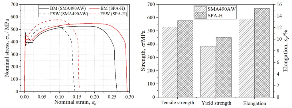
- FSW Joints: FSW joints of SMA490AW and SPA-H showed high microhardness in the stir zone (SZ) with no HAZ softening, and fractures occurred in the base metal (BM), indicating joint efficiency up to 100% [65, 72, 102].
- LFW Joints: LFW joints achieved high tensile and fatigue strength, with optimized parameters (50 Hz, 50 MPa) preventing defects above the A1 temperature [57]. Weld interface fractures reduced fatigue life due to unbonded flash [133].
- Microstructure: FSW joints displayed fine, equiaxed grains in the SZ, while LFW joints showed bainite-dominated weld centers with decreasing bainite fraction away from the weld [64, 113].
- Fatigue Performance: FSW joints matched BM fatigue strength, while LFW joints showed high fatigue strength, though weld defects reduced life by up to 14.7 times [79, 101].
- Weld Imperfections: Flash at the weld edge caused stress concentration, leading to crack initiation; its removal was recommended to enhance fatigue strength [7, 133].
Figure Name List:
![Figure 1.8 View of FSW [100]](https://castman.co.kr/wp-content/uploads/image-2665.webp)
![Figure 1.9 Welding process of FSW [101]](https://castman.co.kr/wp-content/uploads/image-2666.webp)
![Figure 1.10 Appearance of FSW joints (a) poor quality due to excessive wear of tool pin; (b)
poor quality due to improper consolidation; (c) poor quality due to excessive flash; (d) high
quality [104]](https://castman.co.kr/wp-content/uploads/image-2667-1024x284.webp)
![Figure 1.14 Flash geometry under different oscillation amplitudes (a) 2.0 mm; (b) 2.5 mm;
(c) 3.3 mm; (d) 4.2 mm; (e) 5.5 mm; (f) 6.5 mm [109]](https://castman.co.kr/wp-content/uploads/image-2668-1024x422.webp)
![Figure 1.21 Microhardness of FSW joints (a) S690 steel with HAZ softening; (b) DH36 steel
without HAZ softening [125]](https://castman.co.kr/wp-content/uploads/image-2669-1024x665.webp)
- Figure 1. Typical corroded surface of steel bridge [17]
- Figure 1.10 Appearance of FSW joints [25]
- Figure 1.18 Etched weldment under different oscillation frequency [30]
- Figure 1.20 EBSD maps of BM, WCZ, HAZ, and TMAZ of LFWed rail steel joints [31]
- Figure 1.21 Influence of welding parameters on microhardness distribution [31]
- Figure 1.22 Microhardness distribution along the transverse direction [33]
- Figure 1.23 Influence of welding parameters on microhardness distribution of LFW joints [33]
- Figure 1.27 Ductile-to-fracture behavior of FSW joints [38]
- Figure 1.29 Structure of this dissertation [43]
- Figure 2.1 Joining process and parameters of FSW [47]
- Figure 2.2 Appearance of FSW joints of different steels [47]
- Figure 2.3 Joining process of FSW [50]
- Figure 2.4 Instruments for measurement of weld geometry and welding residual stress [51]
- Figure 2.6 Appearance of tension and fatigue specimens [52]
- Figure 2.7 Fabrication of metallographic samples, tension and fatigue specimens for LFW joints [53]
- Figure 2.9 Confidence interval for DIC measurements [56]
- Figure 3.1 Residual stress distribution in FSW joints [61]
- Figure 3.2 Macrostructure of transverse section of the FSW joint [63]
- Figure 3.3 Microstructure and EBSD IPF of SMA490AW and SPA-H [64]
- Figure 3.4 Microstructure and EBSD IPF of TMAZ-AS and TMAZ-RS [64]
- Figure 3.5 Microhardness of FSW joined SMA490AW and SPA-H [65]
- Figure 3.6 Tensile response measured by DIC for BM and FSW joints [66]
- Figure 3.10 Comparison of strain distribution by FE model and experiment [71]
- Figure 3.13 Fracture position of BM and FSW specimens [73]
- Figure 3.14 Fracture surface of FSW specimens [73]
- Figure 3.17 Ratcheting behaviors in fatigue testing [76]
- Figure 3.20 Cyclic deformations during the first 10 cycles [78]
- Figure 3.21 Axial strain corresponding to the microhardness distribution [80]
- Figure 4.6 Microstructures of SZ for various steels [89]
- Figure 4.7 Microhardness of FSW joints [90]
- Figure 4.8 Yield and fracture condition of Steel1, Steel2, and Steel3 [92]
- Figure 4.9 Axial strain accumulation of different zones [93]
- Figure 4.12 Fracture surface of FSW specimens [95]
- Figure 4.13 Assessment of fatigue life [96]
- Figure 4.15 Weld defects of the welded joints [100]
- Figure 4.17 Fatigue life comparison with and without weld defects [101]
- Figure 4.18 Fracture surface near weld defects [102]
- Figure 5.1 Geometry and residual stress of LFW joints [106]
- Figure 5.2 Comparison of residual stress distribution from previous references [108]
- Figure 5.4 Geometry characteristics of LFW joints [110]
- Figure 5.6 Microhardness distribution of LFW joints [112]
- Figure 5.7 Microstructures of LFW joints [113]
- Figure 5.10 Stress-strain relationship and strain contour of LFW joints [116]
- Figure 5.12 Fracture surface of LFW joint of SMA490AW [118]
- Figure 5.16 Strain distribution of LFW specimen of SPA-H [124]
- Figure 5.17 Fatigue striations and ductile fracture features [124]
- Figure 5.19 S-N curve for LFW joints [126]
- Figure 5.22 Strain contour of LFW specimen with weld interface fracture [129]
- Figure 5.24 Fractography characteristics of weld interface fracture [131]
7. Conclusion:
The study successfully demonstrated that FSW and LFW can produce high-ductility and high-fatigue-strength joints for weathering steels, with Steel3 showing superior corrosion resistance [134]. Optimized welding parameters (e.g., 50 Hz, 50 MPa for LFW) minimized defects, enhancing joint performance, though flash removal is critical to prevent crack initiation [133]. Future work should focus on developing fatigue life prediction models for FSW and LFW joints and extending the study to thicker plates [138].
8. References:
- [11] Y. Wang, Z. Fu, H. Ge, et al., Cracking reasons and features of fatigue details in the diaphragm of curved steel box girder. Eng. Struct., 2019, 201, 109767.
- [12] L. Kim, Fatigue strength improvement of longitudinal fillet welded out-of-plane gusset joints using air blast cleaning treatment. Int. J. Fatigue, 2013, 48, 289-299.
- [13] Z. Li, T. Chan, & R. Zheng. Statistical analysis of online strain response and its application in fatigue life assessment of floating wind turbine structure. Ocean Eng., 2019, 171, 139-150.
- [25] Y. Sharifii & R. Rahgozar. Fatigue notch factor in steel bridges due to corrosion. Arch. Civ. Mech. Eng., 2009, 9(4), 75-83.
- [26] A. Lichtenstein. The Silver Bridge Collapse Recounted, J. Perform. Constr. Facid., 1993, 7(4), 249-261.
- [27] H. Salem & H. Helmy. Numerical investigation of collapse of the Minnesota I-35W bridge. Eng. Struct., 2014, 59, 635-645.
- [39] B. Michel & Z. S. Mehdi. Effect of severe corrosion on fatigue life of steel. J. Struct. Eng., 1997, 123(11), 1478-1484.
- [51] American Society for Testing and Materials International, Standard specification for high-strength low-alloy structural steel, up to 50 ksi [345 MPa] minimum yield point, with atmospheric corrosion resistance, ASTM A588, 2019.
- [65] H. Zhang & J. Liu. Microstructure characteristics and mechanical property of aluminum alloy/stainless steel lap joints fabricated by MIG welding-brazing process. Mater. Sci. Eng. A, 2011, 528(19-20), 6179-6185.
- [75] S. D. Mesharam, T. Mohandas, & G. M. Reddy. Friction welding of dissimilar pure metals, J. Mater. Process. Technol., 2007, 194(1), 330-337.
- [76] S. Fukumoto, H. Tsubakino, & T. Yamamoto. Friction welding of aluminum to stainless steel. Weld. Int., 2002, 16(2), 110-115.
- [87] S. Jones, Low force friction welding. What is it?, 2020. [Online]. Available: https://blog.mtwelding.com/low-force-friction-welding.
- [88] A. V.iris, G. Papzafeiropoulos, & A. Tsains, A comparison between friction stir welding, linear friction welding and rotary friction welding. Adv. Manuf, 1.4 (4), 351-360.
- [124] Y. Su, W. Li, X. Wang, et al. The sensitivity analysis of microstructure and mechanical properties to welding parameters for linear friction welded rail steel joints. Mater. Sci. Eng. A, 2019, 764, 138-147.
- [136] J. Besudet, G. Rückert, & F. Cortial, Fatigue behavior of FSW high-yield strength steel welds for shipbuilding application. Weld. World, 2020, 64(6), 1175-1185.
- [147] Y. Wang, S. Tsusumi, T. Kawakubo, et al. Microstructure, mechanical properties and fatigue behaviors of linear friction welded weathering steels. Int. J. Fatigue, 2022, 154, 106-117.
9. Copyright:
- This material is a paper by "Wang, Y.". Based on "Development of FSW and LFW Joints with High Ductile and Fatigue Strength for Weather".
- Source of the paper: Not provided in the document.
This material is summarized based on the above paper, and unauthorized use for commercial purposes is prohibited.
Copyright © 2025 CASTMAN. All rights reserved.
Paper Summarize:
The dissertation investigates the application of Friction Stir Welding (FSW) and Linear Friction Welding (LFW) to join weathering steels, achieving high ductility and fatigue strength through optimized welding parameters. Experimental results demonstrate that FSW and LFW joints of steels like SMA490AW, SPA-H, and high-phosphorus variants (Steel1, Steel2, Steel3) exhibit superior corrosion resistance, with Steel3 outperforming others, and high joint efficiency due to strong weld zones [5, 102]. The study highlights the importance of removing weld flash to mitigate stress concentration and proposes future research into fatigue life prediction models for broader structural applications [133, 138].
Key questions and answers about the research:
Q1. How does the corrosion resistance of different weathering steels compare in this study?
A1. The corrosion resistance index ranked Steel3 > Steel2 > SPA-H > Steel1 > SMA490AW, indicating Steel3’s superior anti-corrosion performance (Section 5, Page 5).
Q2. What are the key advantages of FSW joints for weathering steels?
A2. FSW joints exhibit high microhardness in the stir zone, no HAZ softening, and fractures in the base metal, achieving up to 100% joint efficiency (Section 3.2.3, Page 65; Section 4.2, Page 102).
Q3. How do LFW welding parameters affect joint quality?
A3. Optimized LFW parameters (50 Hz, 50 MPa) above the A1 temperature prevent weld defects, enhancing tensile and fatigue strength (Section 5.2, Page 57).
Q4. What role do weld defects play in the fatigue performance of FSW joints?
A4. Weld defects in FSW joints, such as unbonded flash, reduce fatigue life by up to 14.7 times due to stress concentration and crack initiation (Section 4.4, Page 101).
Q5. How does microstructure influence the mechanical properties of LFW joints?
A5. LFW joints show a bainite-dominated weld center with high microhardness, transitioning to ferrite-dominated regions, enhancing strength but reducing ductility if defects are present (Section 5.2, Page 113).
Q6. What future research is recommended to improve FSW and LFW applications?
A6. Developing novel fatigue life prediction models and studying thicker plates are recommended to enhance the structural application of FSW and LFW joints (Section 6.2, Page 138).