Miguel Angel Reyes Belmonte and Colin D. Copeland
University of Bath
Drummond Hislop, George Hopkins, and Adrian Schmieder
HiETA Technologies Ltd
Scott Bredda
GE Precision
Sam Akehurst
University of Bath
Abstract
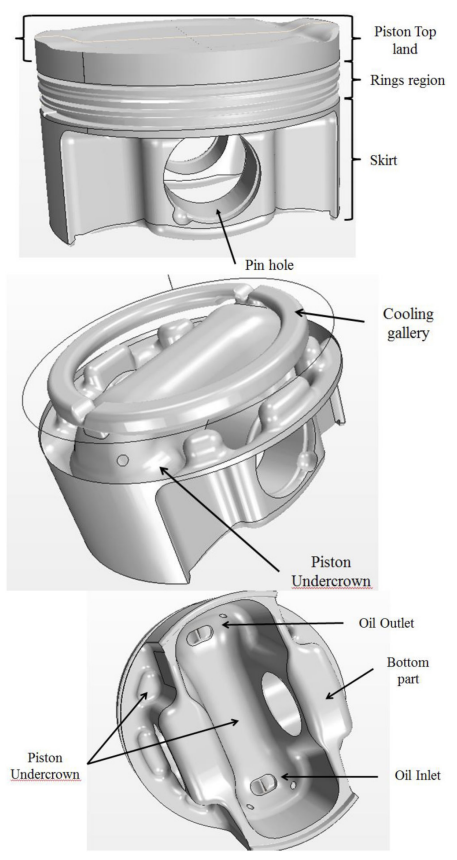
Pressure and temperature levels within a modern internal combustion engine cylinder have been pushing to the limits of traditional materials and design. These operative conditions are due to the stringent emission and fuel economy standards that are forcing automotive engineers to develop engines with much higher power densities. Thus, downsized, turbocharged engines are an important technology to meet the future demands on transport efficiency. It is well known that within downsized turbocharged gasoline engines, thermal management becomes a vital issue for durability and combustion stability. In order to contribute to the understanding of engine thermal management, a conjugate heat transfer analysis of a downsized gasoline piston engine has been performed. The intent was to study the design possibilities afforded by the use of the Selective Laser Melting (SLM) additive manufacturing process. Thus, the study here considers the original aluminum (aluminum alloy 2618A T6) piston with added cooling galleries and weight-saving lattice structures that can be achieved using SLM. An oil cooling gallery was introduced near the piston crown to allow a temperature reduction on the top land and a more homogeneous temperature distribution across the crown. Better temperature control should allow the combustion process to be less sensitive to knocking and preignition. In addition, a shift in the top ring groove due to better cooling will help to reduce crevice volume thereby reducing engine emissions. The ultimate aim is to show that this new additive manufacturing technique applied to piston design could be used to enable further downsizing for fuel economy by increasing engine compression ratio and boost pressure with improved combustion stability and phasing.
현대식 내연 기관 실린더 내의 압력 및 온도 수준은 기존 재료 및 디자인의 한계에 도달했습니다. 이러한 작동 조건은 자동차 엔지니어가 훨씬 더 높은 출력 밀도를 가진 엔진을 개발하도록 하는 엄격한 배기 가스 및 연비 표준 때문입니다.
따라서 소형화된 터보차저 엔진은 운송 효율성에 대한 미래의 요구를 충족시키는 중요한 기술입니다. 소형 터보차저 가솔린 엔진 내에서 열 관리가 내구성과 연소 안정성에 중요한 문제가 된다는 것은 잘 알려져 있습니다.
엔진 열 관리의 이해에 기여하기 위해 소형 가솔린 피스톤 엔진의 복합 열전달 해석을 수행했습니다. 목적은 SLM(Selective Laser Melting) 적층 제조 공정을 사용하여 제공되는 설계 가능성을 연구하는 것이었습니다.
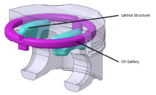
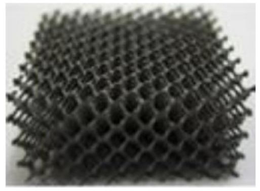
따라서 여기에서 연구는 SLM을 사용하여 달성할 수 있는 냉각 갤러리 및 중량 절감 격자 구조가 추가된 원래의 알루미늄(알루미늄 합금 2618A T6) 피스톤을 고려합니다.
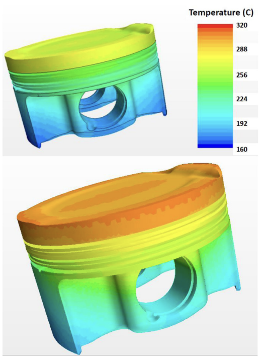
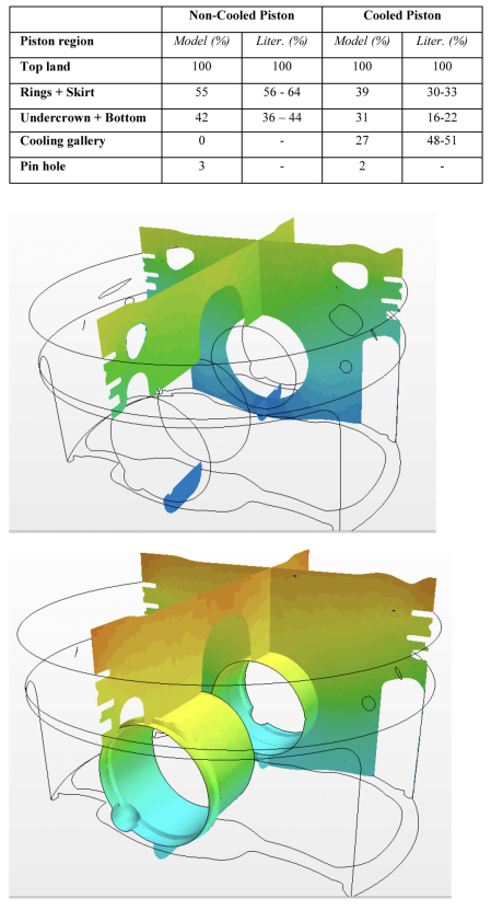
피스톤 크라운 근처에 오일 냉각 갤러리가 도입되어 탑 랜드의 온도 감소와 크라운 전체의 균일한 온도 분포를 가능하게 했습니다. 더 나은 온도 제어는 연소 과정이 노킹 및 예인화에 덜 민감하도록 허용해야 합니다.
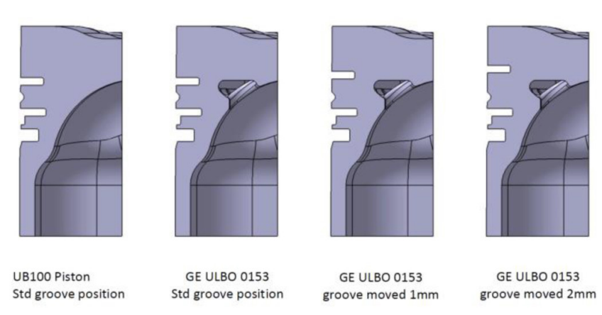
또한 더 나은 냉각으로 인한 상단 링 홈의 이동은 틈새 부피를 줄여 엔진 배기가스를 줄이는 데 도움이 됩니다.
궁극적인 목표는 피스톤 설계에 적용된 이 새로운 적층 제조 기술을 사용하여 연소 안정성 및 위상을 개선하여 엔진 압축비 및 부스트 압력을 증가시켜 연비를 위한 추가 소형화를 가능하게 할 수 있음을 보여주는 것입니다.
![Figure 1. Temperature field based on RTM measurement from a 1,6 l GTDI > 90kW/l [2]. Left: Spray cooled piston, Right: Salt core channel cooled.](https://castman.co.kr/wp-content/uploads/l-2.-Left-Spray-cooled-piston-Right-Salt-core-channel-cooled..png)
![Figure 2. Heat flow ratio distribution for a spray jet cooled diesel piston (left) and with a cooling channel (right) [1]](https://castman.co.kr/wp-content/uploads/Figure-2.-Heat-flow-ratio-distribution-for-a-spray-jet-cooled-diesel-piston-left-and-with-a-cooling-channel-right-1.png)
![Figure 4. Oil heat transfer coefficient dependency with operative conditions. Top: Shaking frequency and oil flow [9]. Center: Oil flow [9]. Bottom: with piston position and region inside the cooling gallery [10].](https://castman.co.kr/wp-content/uploads/Figure-4.-Oil-heat-transfer-coefficient-dependency-with-operative-conditions..png)
![Figure 4. (cont.) Oil heat transfer coefficient dependency with operative conditions. Top: Shaking frequency and oil flow [9]. Center: Oil flow [9]. Bottom: with piston position and region inside the cooling gallery [10].](https://castman.co.kr/wp-content/uploads/Figure-4.-cont.-Oil-heat-transfer-coefficient-dependency-with-operative-conditions.png)
References
- MAHLE GmbH, ed., “Pistons and engine testing”. MTZ, 2012.
- Mohr, U., “Future powertrain improvements”, Mahle internal
presentation, October 2013. - Carey, C., McAllister, M., Sandford, M., Richardson, S. et al.,
“Extreme engine downsizing”, Innovations in Fuel Economy
and Sustainable Road Transport, pp. 135-147, Woodhead
Publishing, 2011. - Turner, J., Popplewell, A., Patel, R., Johnson, T. et al., “Ultra
Boost for Economy: Extending the Limits of Extreme Engine
Downsizing,” SAE Int. J. Engines 7(1):387-417, 2014,
doi:10.4271/2014-01-1185. - Kruth, J., Froyen, L., Van Vaerenbergh, J., Mercelis, P. et al., “Selective laser melting of iron-based powder”, Journal of Materials Processing Technology, vol. 149, pp. 616-622, June 2004.
- Bremen, S., Meiners, W. and Diatlov, A., “Selective laser melting” LTJ, vol. 9, pp. 33-38, Apr. 2012.
- Min, K., “The effects of crevices on the engine-out hydrocarbon emissions in spark ignition engines”. PhD thesis, Massachusetts Institute of Technology, 1994.
- CD-Adapco, http://www.cd-adapco.com/products/star-ccm Prasad, R. and Samria, N., “Transient heat transfer analysis in an internal combustion engine piston”, Computers & Structures, vol. 34, no. 5, pp. 787-793, 1990.
- Singh, V., Upadhyay, P. and Samria, N., “Some heat transfer studies on a diesel engine piston”, International Journal of Heat and Mass Transfer, vol. 29, pp. 812-814, May 1986.
- Wu, H. and Chiu, C., “A study on the characteristics of heat transfer in an engine piston”, KSME Journal, vol. 2, pp. 19-27, 1988.
- Varghese, M., Goyal, S., and Agarwal, A., “Numerical and Experimental Investigation of Oil Jet Cooled Piston,” SAE Technical Paper 2005-01-1382, 2005, doi:10.4271/2005-01-1382.
- Kajiwara, H., Fujioka, Y., and Negishi, H., “Prediction of Temperatures on Pistons with Cooling Gallery in Diesel Engines using CFD Tool,” SAE Technical Paper 2003-01-0986, 2003,
- doi:10.4271/2003-01-0986. Pan, J., Nigro, R., and Matsuo, E., “3-D Modeling of Heat Transfer in Diesel Engine Piston Cooling Galleries,” SAE Technical Paper 2005-01-1644, 2005, doi:10.4271/2005-01-1644.
- Thiel, N., Weimar, H., Kamp, H., and Windisch, H., “Advanced Piston Cooling Efficiency: A Comparison of Different New Gallery Cooling Concepts,” SAE Technical Paper 2007-01-1441, 2007, doi:10.4271/2007-01-1441.
- Adamczyk, A., Kaiser, E. and Lavoie, G. “A combustion bomb study of the hydrocarbon emissions from engine crevices”, Combustion science and technology, vol. 33, no. 5-6, pp. 261-277, 1983.