This technical summary is based on the academic paper "Complete Simulation of High Pressure Die Casting Process" published by Matti Sirviö, Sami Vapalahti, and Jukka Väinölä of VTT Industrial Systems. It was analyzed and summarized for HPDC experts by CASTMAN experts with the help of LLM AI such as Gemini, ChatGPT, and Grok.
Keywords
- Primary Keyword: HPDC Shot Sleeve Simulation
- Secondary Keywords: Air Entrapment HPDC, Plunger Speed Optimization, Casting Porosity, Fluid Flow Simulation, Cavity Filling Simulation, Die Casting Defects
Executive Summary
- The Challenge: Gas porosity, often caused by air entrapped during the shot sleeve's pre-filling phase, is a critical defect in High-Pressure Die Casting (HPDC). Optimizing the plunger movement to prevent this has traditionally relied on costly and inaccurate trial-and-error methods.
- The Method: Researchers utilized advanced fluid flow simulation to model the shot sleeve process. They compared the effects of different plunger speed and acceleration profiles on wave formation and the amount of air trapped in the molten metal.
- The Key Breakthrough: The study proved that a plunger profile with two constant accelerations creates a single, stable wave front, drastically minimizing air entrapment. In contrast, a conventional profile with an abrupt acceleration causes wave collision and traps significant air pockets (as shown in Figure 7 & 8 vs. Figure 4 & 5).
- The Bottom Line: Simulating the shot sleeve process is not just beneficial—it is essential for optimizing plunger movement. This data-driven approach directly reduces porosity, leading to higher quality castings, less scrap, and shorter production setup times.
The Challenge: Why This Research Matters for HPDC Professionals
For decades, engineers have grappled with porosity, a primary cause of component failure in HPDC. While solidification modeling is widely used to predict shrinkage porosity, gas porosity remains a persistent challenge. Gas porosity has four main causes, but a major contributor is trapped air entrained in the injection system and cavity during the high-velocity metal injection process (Ref. [1], [3]).
In complex processes like aluminum die casting, the high velocity of the liquid metal means that inertia and flow momentum play a crucial role. Sub-optimal flow can cause splashing and jetting, leading to unpredictable filling and air entrapment. When dealing with complex part geometries, accurately predicting this behavior using only empirical knowledge or workshop experience is, as the paper states, "virtually impossible" (Ref. [3]). The result is often a lengthy and expensive cycle of trial-and-error to achieve acceptable quality. This research tackles the problem at its source: the shot sleeve.
The Approach: Unpacking the Methodology
To isolate and solve the problem of air entrapment, the researchers focused on simulating the very first stage of injection: the shot sleeve pre-filling phase. The study posits that the casting process can be divided into three phases: the pre-filling phase, the mould filling phase, and the final pressure phase. The goal of the pre-filling phase is to move the liquid metal toward the gate without trapping air.
The researchers used fluid flow simulation capable of solving the complete Navier-Stokes equations and modeling the free surface of the liquid metal. This allowed them to accurately track complex flow fronts and predict air entrapment. The core of the study involved simulating and comparing two distinct plunger movement profiles:
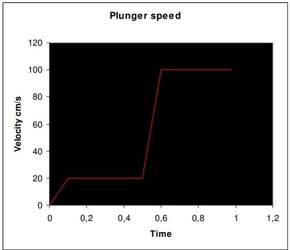
- A conventional profile: The plunger moves at a constant low speed and then accelerates rapidly (Figure 1).
- An optimized profile: The plunger moves with two constant, controlled accelerations (Figure 7).
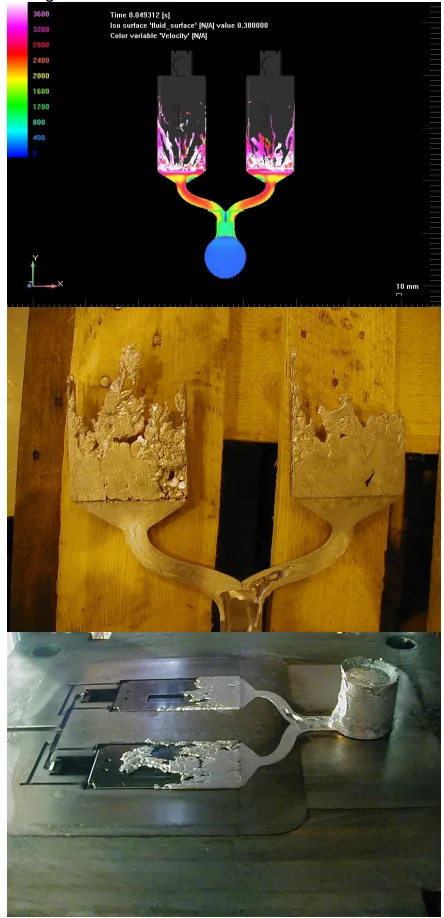
By visualizing the resulting wave formation and the volume fraction of air mixed with the metal, they could directly quantify the effectiveness of each approach. The simulation results were then verified with physical short shot experiments (Figure 9).
The Breakthrough: Key Findings & Data
The simulation results provide a clear, visual demonstration of how plunger control directly impacts quality.
- Finding 1: Unoptimized Plunger Profiles Create Air Pockets: The conventional profile, featuring a constant speed followed by a sharp acceleration, created a shallow initial wave. The second, high-acceleration phase generated a strong splashing wave that crashed over the first one. This collision, shown clearly in Figure 3 and Figure 4, traps a "considerable quantity of air" inside the molten metal before it even enters the die cavity. Figures 5 and 6 illustrate this large air bubble formed inside the sleeve.
- Finding 2: Optimized Acceleration Creates a Stable Wave Front: The profile using two constant accelerations produced a much different result. The wave fronts formed by each acceleration stayed together, forming a single, combined wave front that advanced smoothly down the sleeve. As shown in Figure 7, this stable wave hits the cylinder head cleanly, resulting in "minimal air entrapment" (Figure 8).
- Finding 3: Shot Sleeve Simulation is a Prerequisite for Accurate Cavity Filling Analysis: The study demonstrated that conditions created in the shot sleeve are the critical starting point for the rest of the process. The paper concludes that it is "vital to simulate shot sleeve process before cavity filling simulations" to ensure the data used for cavity analysis is reliable and accurate (Figure 9). The optimization of plunger movement, the authors state, is "impossible to achieve without simulation."
Practical Implications for HPDC Products
- For Process Engineers: The findings provide a clear directive: plunger speed profiles must be engineered, not guessed. The research suggests that by simulating and implementing an optimal, multi-stage acceleration profile (as seen in Figure 7), you can proactively minimize air entrapment at the very start of the process. This allows for more precise control of HPDC machines and a reduction in setup time, as noted in the paper's conclusion.
- For Quality Control: The direct visual correlation shown between the plunger profile (Figure 1 vs. Figure 7) and the resulting air entrapment (Figure 5 vs. Figure 8) provides a powerful tool for proactive quality assurance. Instead of just inspecting for gas porosity, teams can ensure the machine parameters are set to prevent it from forming in the first place.
- For Die Design: This study emphasizes that the entire system is interconnected. The conclusion states that "cavity geometry including the design and locations of gates and vents was found to be very important." The clean, air-free metal flow generated by an optimized shot sleeve process ensures that the subsequent filling of the gates and cavity performs as designed, preventing further defects.
Paper Details
Complete Simulation of High Pressure Die Casting Process
1. Overview:
- Title: Complete Simulation of High Pressure Die Casting Process
- Author: Matti Sirviö, Sami Vapalahti, Jukka Väinölä (VTT Industrial Systems, Conrod Team)
- Year of publication: Not specified in the document (circa 1999, based on references).
- Journal/academic society of publication: Not specified; likely a conference proceeding (e.g., NADCA).
- Keywords: High Pressure Die Casting (HPDC), Simulation, Shot Sleeve, Fluid Flow, Air Entrapment, Porosity, Plunger Speed.
2. Abstract:
The use of simulation programs saves time and reduces the costs of the casting system design. At the same time it is possible to meet stringent product quality. Simulation can make a casting system optimal: it enables the producing of sound, high-quality castings with fewer experiments. Furthermore environmental savings and economical use of materials can be achieved when the number of test castings is reduced. Foundries use now widely simulation codes that are based on a thermal conduction model where thermal conduction in the melt and liberation of latent heat during solidification are considered. Fluid flow simulations are less used. However, e.g. aluminium die casting is so complicated in which flow momentum plays a crucial role in the mould filling process due to the high velocity of the liquid metal. Inertia effects may cause splashing, jetting or undesirable filling of the metal flow into mould cavity. When considering complex parts, the accurate prediction of mould filling behaviour using empirical knowledge is nearly impossible. In most of the industrial nations, about 70% of the diecast parts go to the automotive industry. Aluminium diecastings are gaining importance in the production of lightweight vehicle bodies, as for example used in new model Audi cars. Therefore, it is even more vital today that these castings can be produced with the high quality methods. In this context the simulation is becoming more essential in the designing process. This paper describes the advantages of the Shot Sleeve simulations to attain better casting system design in HPDC castings. Filling analysis is used to determine the size and location of the gate as well as proper runner system design for ensuring a complete and balanced filling of the part. Shot sleeve simulations in High Pressure Die Casting process ensures the minimum air entrapment during the pre-filling phase.
3. Introduction:
Computer simulations of various kinds are gradually becoming widely recognised tools in numerous design processes. Simulation codes are widely used in the foundry industry. Computer simulation of the casting process began with solidification modelling. For this reason, the codes are used, in most cases, for heat transfer calculations in order to predict hot spots and to avoid porosity in castings¹. Fluid flow simulations are less widely used. One of the reasons is that only a few of the codes can adequately simulate highly dynamic flows. On the other hand, all of the known methods require a significant degree of human effort during the pre-processing phase of the simulation process. This excludes the everyday practical use of such methods, when complicated geometries are utilised: The enmeshing process takes simply too long and often calculation meshes must be fixed in order to achieve converged solutions. Furthermore, although the casting geometry has been received from the workshop, adding the channels may involve considerable effort. For these reasons, many foundries tend to trust to their empirical knowledge². However, fluid flow simulations should be used in many instances, e.g. in aluminium die casting, which is particularly because flow momentum plays a crucial role in the mould filling process due the high velocity of the liquid metal. Inertia effects may cause splashing, jetting or undesirable filling of the metal flow into mould cavity. When considering complex parts, the accurate prediction of mould filling behaviour using only empirical knowledge is virtually impossible³. It is commonly accepted that shrinkage and gas are two major causes of porosity. The shrinkage porosity is associated with the hot spot in the casting. The gas porosity has four different reasons: 1) Trapped air that is entrained in the injection system and cavity: 2) Gas generated from burned lubricants; 3) Gas generated from water that may be in cavity and 4) Hydrogen gas. The gas porosity due to the trapped air is an unwanted byproduct of relatively high velocity injection method used. Gas entrapment is caused by turbulent flow pattern generated during metal injection process. The location, size and total volume of contained gas porosity are influenced by the method chosen to fill cavity with molten alloy. In high pressure die casting, some efforts have been made to reduce air entrapment by the modification of conventional injection shot profile taking advantages of the development of advanced and reliable control systems.
4. Summary of the study:
Background of the research topic:
High-Pressure Die Casting is a dominant manufacturing process, particularly for the automotive industry. However, it is susceptible to quality issues like gas porosity, which is frequently caused by air being trapped in the molten metal during the high-speed injection process.
Status of previous research:
Most simulation efforts in the foundry industry focused on thermal and solidification modeling to predict hot spots. Fluid flow simulations were less common due to their complexity. As a result, critical process parameters like the plunger injection profile were typically determined by inefficient trial-and-error methods.
Purpose of the study:
To demonstrate that simulating the shot sleeve pre-filling phase is essential for designing an optimal HPDC process. The study aimed to show how optimizing the plunger's movement through simulation could directly minimize air entrapment and, consequently, improve final casting quality.
Core study:
The research conducted a comparative study using fluid flow simulation. It modeled two different plunger speed profiles: a conventional profile with a single, sharp acceleration and an optimized profile with two constant accelerations. The study analyzed the resulting metal wave formation, velocity, and the volume of entrapped air for each profile.
5. Research Methodology
Research Design:
The study used a comparative research design, simulating two distinct plunger movement profiles within a cold chamber HPDC shot sleeve. The goal was to compare the resulting fluid dynamics and quantify the amount of air entrapment in each scenario.
Data Collection and Analysis Methods:
Data was generated using a fluid flow simulation program (acknowledged as Flow-3D) capable of solving the complete Navier-Stokes equations and modeling free-surface flow. This allowed for detailed visualization of metal velocity, wave formation, and the volume fraction of air versus metal. The simulation findings were validated using physical short shot experiments.
Research Topics and Scope:
The research focused specifically on the pre-filling phase of the cold chamber die casting process. Its scope was limited to the fluid dynamics within the shot sleeve and the direct impact of plunger speed and acceleration profiles on wave formation and air entrapment.
6. Key Results:
Key Results:
- A conventional plunger profile (constant speed followed by high acceleration) creates two distinct waves that collide, trapping a large air bubble within the molten metal (Figures 1-6).
- An optimized plunger profile using two constant accelerations creates a single, stable, combined wave front that fills the sleeve smoothly with minimal air entrapment (Figures 7-8).
- The paper concludes that optimizing plunger movement is "impossible to achieve without simulation" and that shot sleeve simulation is "vital" to perform before cavity filling simulations to ensure reliable data (Figure 9, Conclusion).
Figure Name List:
- Fig. 1. Slow shot profile, that has two plunger accelerations.
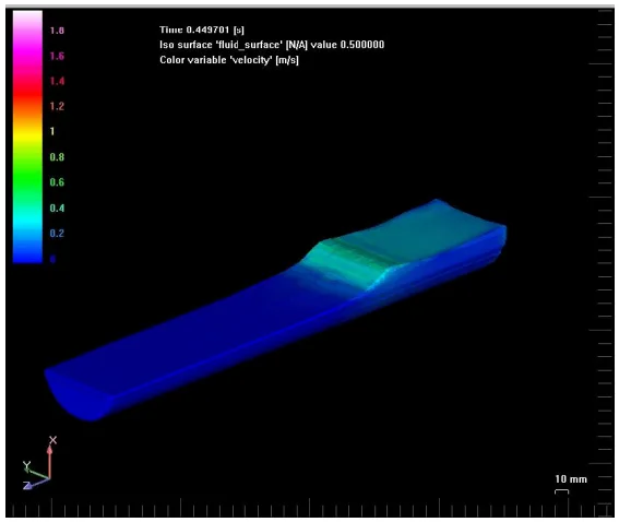
- Fig.2. First acceleration cause shallow wave. (Colour scale:Meters per second).
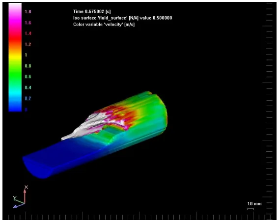
- Fig.3. Second acceleration causes splashing wave which is crushing shallow wave.
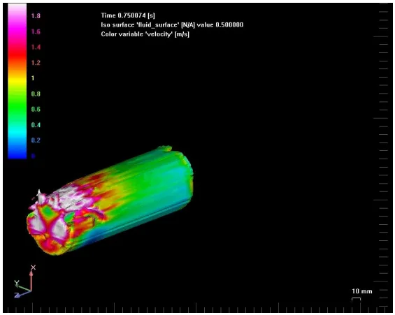
- Fig.4. When these two waves collide, a large air entrapment is formed inside the waves.
- Fig.5 and 6.. Volume fraction picture illustrates air entrapment and how the air mixes with the metal. In these pictures, it can be seen how the two waves form an air bubble inside the sleeve. (Colour scale - volume fraction: White is 100% metal and blue is 100 % air)
- Fig. 7. The plunger is moved using two constant accelerations. The two waves form a combined wave front which hits the cylinder head. Minimal air entrapment occurs. (Colour scale: Meters per second).
- Fig. 8. The two waves form a combined wave front which hits the cylinder head. Minimal air entrapment occurs.
- Fig.9. Short shot experiments proved that it is vital to simulate shot sleeve process before cavity filling simulations.
7. Conclusion:
Shot sleeve simulations give valuable information to the manufacturer what will be the final quality of the product. If the HPDC machines could be controlled according to these simulation results, it would mean substantial savings in lead times, production planning and high decrease in scrap production. Along with cavity pre-fill percentage and transition time, cavity geometry including the design and locations of gates and vents was found to be very important parameter to be considered to achieve optimal cavity fill in terms of air entrapment. The shot sleeve process is quite difficult process to simulate and the efficient usage of results require the possibility to control HPDC machines. Following direct improvements could be gained:
- Improvement of the casting quality by minimising the entrapped air during the shot sleeve process
- Minimising set up time during the start of casting process
- Possibility to control HPDC machines more precisely
- Optimisation of the whole casting process by controlling filling with optimal plunger movement
- Shorter lead time during the tool designing process
- Less scrap and waste production when new design is taken on the use.
Simulations demonstrated the importance of calculating the filling of the casting in Aluminium Casting process. With certain castings, there are situations where the channel design can prevent the proper filling of the casting. These situations are very difficult to predict without simulations. Shot Sleeve simulations proved that it is extremely important to simulate the process with actual plunger movements. The optimisation of plunger movement is impossible to achieve without simulation. It is important that the simulation program employed is able to model the free surfaces of the flow correctly in order to predict air entrapment.⁵
8. References:
- [1] Sirviö, M. and Martikainen, H. “Simultaneous engineering between workshops and foundries”. Int. Conf. on Best Practices in the Production, Processing and Thermal Treatment of Castings. Singapore, 10 - 12 Oct. 1995. Paper 17-1-6
- [2] Sirviö, M. and Louvo, A. “Use of simulated porosity for avoidance of casting defects”. International GIFA Congress Metal Casting '94 (GIFA '94). Dusseldorf, 15 - 18 June 1994. German Foundrymen's Association (1994), 8 p.
- [3] Thorpe, W., Ahuja,V., Jahedi, M., Cleary,P. and Stokes, N,. “Simulation of Fluid Flow Within the Die Cavity in High Pressure Die Casting Using Smooth Particle Hydrodynamics”. Trans 20th Int Die Casting Cong & Expo, NADCA, Cleveland, 1999, T99-014.
- [4] Brevick, Jerald R., Professor, “Computer Flow Modeling of Cavity Pre-fill Effectsin High Pressure Die Casting”. Trans 20th Int Die Casting Cong & Expo, NADCA, Cleveland, 1999, T99-011.
- [5] Sirviö, M. “Computer integrated patternless casting process for SMEs (Project BE - 1969)”. EUR 18160. Proceedings of the Conference on Industrial Technologies. Toulouse, 27 - 30 Oct. 1997. European Commission. Luxembourg (1998), 116
- [6] Venkatsen and Shivipouri, “Numerical investigation of the effect of gate size of die casting parts”. Trans 18th Int Die Casting Cong & Expo, NADCA, Indianapolis, pp.66-74.
Expert Q&A: Your Top Questions Answered
Q1: Why is simulating the shot sleeve so important when most people focus on cavity filling?
A1: This paper proves that the initial conditions of the melt are established in the shot sleeve. An improper plunger movement can introduce a "considerable quantity of air" before the metal even reaches the gate, as shown in Figures 4, 5, and 6. The paper states it is "vital to simulate shot sleeve process before cavity filling simulations" to get reliable data for the entire process (Conclusion, Figure 9).
Q2: What specific plunger movement profile did the research find to be most effective at reducing air entrapment?
A2: The study found a profile using two constant accelerations to be far superior. This creates a single, combined wave front that moves smoothly down the sleeve with "minimal air entrapment," as illustrated in Figures 7 and 8. This contrasts sharply with a conventional profile that causes waves to collide and trap air.
Q3: Is it enough to just use a slow plunger speed to avoid air entrapment?
A3: No, the paper clarifies that if the velocity is too low, "the resulting wave will not be sufficiently high" to properly fill the chamber cross-section. Conversely, a velocity that is too high "results in a surging wave that traps air." The key is not just speed, but the optimal acceleration profile to create a stable, banked-up wave (Shot Sleeve simulation section).
Q4: Besides better quality, what are the business benefits of implementing this simulation approach?
A4: The conclusion section lists several direct business benefits: "substantial savings in lead times," a "high decrease in scrap production," "minimising set up time," and a "shorter lead time during the tool designing process." It allows for process optimization before any metal is cast, saving time and materials.
Q5: Can this optimization be done with empirical knowledge or trial-and-error?
A5: The paper argues that it's practically impossible for complex parts. It states, "the optimisation of plunger movement is impossible to achieve without simulation" (Conclusion). Furthermore, predicting fill behavior "using only empirical knowledge is virtually impossible" (Introduction).
Conclusion & Next Steps
This research provides a valuable roadmap for enhancing component quality in HPDC. By shifting focus to the often-overlooked shot sleeve phase, the findings offer a clear, data-driven path toward minimizing air entrapment, reducing porosity defects, and optimizing production from the very first step.
At CASTMAN, we are dedicated to applying the latest industry research to solve our customers' most challenging die casting problems. If the issues discussed in this paper resonate with your operational goals, contact our engineering team to discuss how we can help you implement these advanced principles in your components.
Copyright
- This material is a paper by "Matti Sirviö, Sami Vapalahti, Jukka Väinölä". Based on "Complete Simulation of High Pressure Die Casting Process".
- Source of the paper: VTT Industrial Systems, as per the publication details on the original document.
This material is for informational purposes only. Unauthorized commercial use is prohibited. Copyright © 2025 CASTMAN. All rights reserved.