This introduction paper is based on the paper "Model Characterization of High-Voltage Layer Heater for Electric Vehicles through Electro-Thermo-Fluidic Simulations" published by "Energies (MDPI)".
1. Overview:
- Title: Model Characterization of High-Voltage Layer Heater for Electric Vehicles through Electro-Thermo-Fluidic Simulations
- Author: Kwon Joong Son
- Year of publication: 2024
- Journal/academic society of publication: Energies
- Keywords: high-voltage heater; layer heater; computational fluid dynamics; transient heat transfer; multiphysics; transfer function modeling
2. Abstract:
This paper focuses on the modeling and analysis of a high-voltage layer heater (HVLH) designed for environmentally friendly vehicles, including electric vehicles (EVs) and plug-in hybrid electric vehicles (PHEVs), through multiphysics simulations that cover electrical, thermal, and fluid dynamics aspects. Due to the significant expenses and extensive time needed for producing and experimentally characterizing HVLHs, simulation and physical modeling methods are favored in the development stage. This research pioneers the separate modeling of thermal boundary conditions for the heating element (TFE) within the electrical domain, enabling the calculation of Joule heating and the analysis of transient conjugate heat transfer. Moreover, this research initiates the application of transfer function modeling for the HVLH component, expanding its use to the broader context of heating, ventilation, and air conditioning (HVAC) systems. The simulation results, which include calculations for Joule heating and temperature fields based on input voltage and flow conditions, closely follow experimental data. The derived transfer function, along with the regression parameters, precisely predicts the dynamic behavior of the system. The simulation-based modeling approach presented in this study significantly advances the design and control of environmentally friendly electric heating systems, providing a sustainable and cost-effective solution.
3. Introduction:
Electric vehicles (EVs) and plug-in hybrid electric vehicles (PHEVs) require battery-powered heaters for cabin heating, defrosting, and battery preheating, as they cannot consistently rely on waste heat from an engine or electric motor. High-voltage heaters (HVHs) are commonly used, with positive temperature coefficient (PTC) heaters being a prevalent type. While PTC heaters offer self-limiting temperature characteristics, they consume significant power at low temperatures and have limitations in achieving compact and lightweight designs. This paper focuses on an alternative HVH type utilizing a resistor layer made of a silver-palladium alloy, designed to overcome PTC heater limitations. This high-voltage layer heater (HVLH) functions as a heat exchanger, heating coolant via a layered thick-film heating element (TFE). It offers advantages such as lightweight construction, enhanced heat output and efficiency, use of readily available materials (improving sustainability), and potential energy savings (approximately 18% during initial warming compared to PTC heaters [1]). Heat output is controlled using temperature sensors and pulse width modulation (PWM).
4. Summary of the study:
Background of the research topic:
Environmentally friendly vehicles like EVs and PHEVs necessitate efficient and compact heating systems. Traditional PTC heaters have drawbacks, leading to research into alternative HVH technologies like those based on silver-palladium alloy resistor layers (HVLH). These HVLHs offer benefits in terms of size, weight, efficiency, and material sustainability.
Status of previous research:
Previous academic research on HVLHs has primarily focused on virtual performance verification and design optimization using numerical analysis of fluid flow and heat transfer, often concentrating on steady-state conditions [9,10]. Some studies, including earlier work by the author [11,12], improved the modeling of the TFE structure and included Joule heating calculations. However, a significant limitation in prior studies is their reliance on steady-state analysis, which does not adequately capture the dynamic behaviors and transient responses crucial for effective controller design and system-level integration into HVAC systems.
Purpose of the study:
The objective of this study is to acquire time response data through transient multiphysics analysis of an HVLH and to develop an accurate transfer function model for the HVLH. This model is intended to facilitate the dynamic behavior prediction of the HVLH and its integration into system-level HVAC simulations (e.g., using Modelica or Simulink) for developing and implementing control strategies.
Core study:
The core of this study involves comprehensive electro-thermo-fluidic simulations of a specific HVLH design featuring symmetric serpentine flow paths. This includes:
- Separate modeling of the thermal boundary conditions for the thick-film heating element (TFE) within the electrical domain.
- Calculation of Joule heating based on applied voltage.
- Analysis of transient conjugate heat transfer under various coolant flow conditions.
- Derivation of a transfer function model from the simulated step response data, characterizing the dynamic behavior of the HVLH.
5. Research Methodology
Research Design:
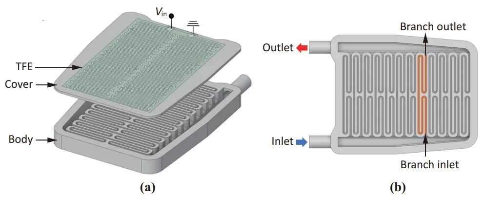
The HVLH unit studied incorporates symmetric serpentine flow paths, maintaining the shape and overall dimensions (177.4 mm × 251.0 mm × 20.5 mm) of an earlier model [11].
- Structure: Designed for large-scale production with die-castable primary structural elements bolted together. Thin conductive (silver-palladium, Ag-Pd) and insulating (alumina, Al2O3) layers are screen-printed on the aluminum alloy (ALDC2) cover plate.
- Heating Element (TFE): The Ag-Pd resistive heating layer (8 µm thick) is sandwiched between an upper (30 µm) and lower (120 µm) alumina insulation layer. It is positioned on the outer surface of the heater, not submerged in coolant. Electrical connection is via a singular input terminal and a ground terminal.
- Flow Channel: Comprises twelve parallel branches originating from a single circular cross-section inlet. Each branch has a four-fold mirror-symmetric serpentine pathway with a rectangular cross-section. The flow channel cavity volume is 183.2 cm³.
- Materials:
- Heater body and cover plate: Aluminum alloy Al-Si-Mg (ALDC2)
- Resistive heating element: Silver-palladium (Ag-Pd)
- Insulation layers: Alumina (Al2O3)
- Coolant: Properties specified in Table 1.
Data Collection and Analysis Methods:
Multiphysics simulations were performed using COMSOL Multiphysics 6.0 with its Composite Materials, AC/DC, CFD, and Heat Transfer modules.
- Governing Equations and Models:
- Fluid Dynamics: Steady, incompressible, turbulent flow modeled using the shear stress transport (SST) k-ω model (Equations (1) and (2) in the paper).
- Electrostatics and Joule Heating: Laplace equation (∇²V = 0) for electric potential (V), electric field intensity (E = -∇V), Ohm's law (J = σE) for current density (J), and Joule heating power generation (Qe = E·J, Equation (4)).
- Heat Transfer: Time-dependent energy balance equation (Equation (3)) for the conductive Ag-Pd medium, incorporating heat conduction and convection. Conjugate heat transfer (CHT) between solid and fluid domains was modeled using the Kays–Crawford turbulent Prandtl number (Prt, Equation (5)).
- Meshing: The fluid and structural solid domains were discretized using 3D elements, while planar-layered shell elements were used for the thin composite TFE structure. This resulted in 32,010,895 3D elements (24,856,397 in fluid, 7,154,498 in solid) and 24,704 layered shell elements.
- Boundary Conditions:
- External aluminum surfaces (excluding inlet/outlet pipes): Convective heat transfer with a coefficient of 5.0 W/m²·K and an ambient temperature of 25 °C.
- Inlet and outlet pipes: Assumed to be insulated.
- Coolant inlet: Temperature of 25 °C, with flow rates of 5, 10, 15, and 20 Liters Per Minute (LPM).
- Input Voltage: A sigmoid-like step signal, increasing from 0 V to 350 V in 0.01 s (Figure 2b).
- Simulation Procedure:
- Initial CFD analysis to obtain a steady-state turbulent flow field.
- Subsequent dynamic conjugate heat transfer analysis over 60 s (data recorded at 1-second intervals), considering the influences of the electric field and Joule heating.
- Transfer Function Modeling:
- The HVLH was modeled as a first-order linear time-invariant (LTI) system.
- The step response for the coolant temperature increase (∆T) from inlet to outlet is given by: ∆T(t) = (1 - e^(-t/tc)) ∆Tss (Equation (6)), where tc is the time constant and ∆Tss is the steady-state temperature increase.
- The corresponding transfer function (TF) is: TF = ∆T(s)/Vin = KDC / (tcs + 1) (Equation (7)), where Vin is the input voltage amplitude and KDC is the DC gain (KDC = ∆Tss / Vin, Equation (8)).
- KDC and tc were determined from the simulation data for each flow rate.
- Regression analysis was performed to express KDC and tc as functions of the volume flow rate Q (LPM), using an inversely proportional function: f(Q) = a/Q + b (Equation (9)).
- The final transfer function incorporating Q was derived as: TF(s; Q) = 0.2687 / ((1.969Q + 43.68)s + Q) (Equation (10)).
Research Topics and Scope:
The research focused on the model characterization of a high-voltage layer heater (HVLH) for electric vehicles. This involved:
- Developing a multiphysics simulation model covering electro-thermo-fluidic aspects.
- Analyzing the transient behavior of the HVLH under step voltage inputs at different coolant flow rates (5, 10, 15, 20 LPM).
- Calculating Joule heating by separately modeling the conductive heating layer in the electrical domain.
- Investigating transient conjugate heat transfer.
- Deriving and validating a transfer function model for the HVLH to enable its use in broader HVAC system modeling and control design.
6. Key Results:
Key Results:
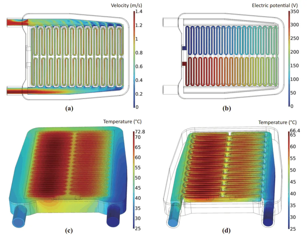
- Flow and Temperature Fields: Simulations provided steady-state flow fields and transient electric and temperature fields for coolant flow rates of 5, 10, 15, and 20 LPM. The electric field reached saturation almost immediately after the step voltage input, while the temperature field exhibited a transient response before reaching steady-state.
- For a 10 LPM flow rate (1.67 × 10⁻⁴ m³/s) at 60 s:
- The velocity field showed decreasing flow speed in branches further from the inlet, with no flow blockages observed (Figure 3a).
- A consistent voltage drop was observed across the TFE (Figure 3b).
- The highest temperature at the heating element reached 72.8 °C (Figure 3c).
- The average coolant temperature at the outlet was 34.4 °C, representing a 9.4 °C increase from the inlet temperature of 25 °C (Figure 3d).
- For a 10 LPM flow rate (1.67 × 10⁻⁴ m³/s) at 60 s:
- Transient Thermal Response:
- The steady-state temperature difference between inlet and outlet (∆Tss) decreased with increasing coolant flow rate (Figure 4a).
- Higher flow rates led to a more rapid initial change in ∆Tss and a shorter time to reach steady state.
- Comparison with Experimental Data: Simulated ∆Tss values showed good agreement with experimental data from [28], with discrepancies ranging from 1.4% to 10.5% across different flow rates (Figure 4b).
- Transfer Function Model:
- The HVLH's dynamic behavior was well-represented by a first-order LTI system.
- Transfer function parameters (DC gain KDC, time constant tc, rise time tr, settling time ts) were derived from simulation data for each flow rate (Table 2). For example:
- At 5 LPM: KDC = 0.0537 °C/V, tc = 10.3 s.
- At 20 LPM: KDC = 0.0133 °C/V, tc = 3.71 s.
- The fitted transfer function curves closely matched the time-dependent simulation data (Figure 5).
- Regression analysis yielded relationships for KDC and tc as functions of flow rate Q (LPM) (Figure 6):
- KDC(Q) = 0.2687 / Q
- tc(Q) = 43.68 / Q + 1.696
- A generalized transfer function incorporating flow rate Q was formulated as:
TF(s; Q) = 0.2687 / ((1.969Q + 43.68)s + Q) (Equation (10)). - The derived transfer function model was demonstrated in a block diagram for simulating step response and PWM control (Figure 7), highlighting its utility for system-level analysis.
Figure Name List:
- Figure 1. HVLH schematic diagram: (a) disassembled illustration of heater consisting of main body with serpentine walls and cover plate with screen-printed heating layer; (b) heater body including symmetric serpentine flow channels with twelve branches in parallel.
- Figure 2. Preprocessing of electro-thermo-fluidic simulation: (a) meshed elements zoomed-in around the coolant inlet and (b) Sigmoid-based step voltage input function.
- Figure 3. Simulation results for inlet flow rate of 10 LPM at 60 s: (a) steady-state velocity magnitude contour plot at the middle cross-section of serpentine flow channels; (b) electric potential contour plot on the conductive heating layer; (c) temperature contour plot on the solid surface; (d) temperature contour plot on the fluid surface.
- Figure 4. Time-dependent thermal analysis results: (a) temperature difference versus time curve for different coolant flow rates, with data points collected every 2 s; (b) bar graphs comparing simulated and experimental results for steady-state temperature increase from inlet to outlet.
- Figure 5. Transfer function curves fitted against simulation data for various LPMs.
- Figure 6. Results from curve fitting of transfer function parameters for (a) steady-state gain and (b) time constant.
- Figure 7. PWM control of high-voltage heat using the transfer function model: (a) block diagram schematic; (b) step response versus PWM response curves.
7. Conclusion:
This study successfully presented a comprehensive modeling and simulation approach for characterizing the transient electro-thermo-fluidic behavior of a high-voltage layer heater (HVLH) and deriving an accurate transfer function.
Key contributions include:
- Advanced HVLH Modeling: This research is the first to model and simulate an HVLH by separately modeling the conductive heating layer in the electric domain. This allows for accurate calculation of Joule heating and analysis of transient conjugate heat transfer, improving predictions of thermal performance and power consumption.
- Pioneering Transfer Function Development: The study pioneers the modeling of the HVLH component's transfer function, which is crucial for its integration into system-level HVAC modeling and for the development and implementation of effective control strategies for electric vehicle heating systems.
- High-Precision Model Validation: The regression analysis for the transfer function and its parameters demonstrated a high degree of precision in reproducing the simulation data, underscoring the reliability of the model for forecasting HVAC system performance.
This research significantly advances the development and management of heating systems in electric vehicles by providing a robust methodology for modeling and simulation. It contributes to the design and enhancement of HVLHs and promotes the adoption of effective heating solutions in the rapidly growing electric vehicle sector. Potential future research directions include the development of new HVLH models with modified flow paths and TFE configurations, as well as comprehensive dynamic modeling and analysis of the entire HVAC system, including the HVLH, to further validate and improve the transfer function model for real-world applications.
8. References:
- [1] Li, B.; Kuo, H.; Wang, X.; Chen, Y.; Wang, Y.; Gerada, D.; Worall, S.; Stone, I.; Yan, Y. Thermal Management of Electrified Propulsion System for Low-Carbon Vehicles. Automot. Innov. 2020, 3, 299–316.
- [2] Lei, S.; Xin, S.; Liu, S. Separate and Integrated Thermal Management Solutions for Electric Vehicles: A Review. J. Power Sources 2022, 550, 232133.
- [3] Park, M.H.; Kim, S.C. Heating Performance Characteristics of High-Voltage PTC Heater for an Electric Vehicle. Energies 2017, 10, 1494.
- [4] Park, M.H.; Kim, S.C. Effects of Geometric Parameters and Operating Conditions on the Performance of a High-Voltage PTC Heater for an Electric Vehicle. Appl. Therm. Eng. 2018, 143, 1023–1033.
- [5] Shin, Y.H.; Ahn, S.K.; Kim, S.C. Performance Characteristics of PTC Elements for an Electric Vehicle Heating System. Energies 2016, 9, 813.
- [6] Paunović, V.; Mitić, V.; Đorđević, M.; Prijić, Z. Electrical Properties of Rare Earth Doped BaTiO3 Ceramics. In Proceedings of the 2017 IEEE 30th International Conference on Microelectronics (MIEL), Nis, Serbia, 9–11 October 2017; pp. 183–186.
- [7] Cap, C.; Hainzlmaier, C. Layer Heater for Electric Vehicles. ATZ Worldw. 2013, 115, 16–19.
- [8] Stifel, T. Optimization and Protection of Traction Batteries with an HV Coolant Heater. ATZ Worldw. 2021, 123, 44–47.
- [9] Dong, F.; Feng, Y.; Wang, Z.; Ni, J. Effects on Thermal Performance Enhancement of Pin-Fin Structures for Insulated Gate Bipolar Transistor (IGBT) Cooling in High Voltage Heater System. Int. J. Therm. Sci. 2019, 146, 106106.
- [10] Dong, F.; Wang, Z.; Feng, Y.; Ni, J. Numerical Study on Flow and Heat Transfer Performance of Serpentine Parallel Flow Channels in a High Voltage Heater System. Therm. Sci. 2022, 26, 735–752.
- [11] Son, K.J. Thermo-Fluid Simulation for Flow Channel Design of 7 kW High-Voltage Heater for Electric Vehicles. J. Korea Converg. Soc. 2022, 13, 191–196.
- [12] Son, K.J. Optimal Power Distribution of High-Voltage Coolant Heater for Electric Vehicles through Electro-Thermofluidic Simulations. Int. J. Automot. Technol. 2023, 24, 995–1003.
- [13] Bellocchi, S.; Leo Guizzi, G.; Manno, M.; Salvatori, M.; Zaccagnini, A. Reversible Heat Pump HVAC System with Regenerative Heat Exchanger for Electric Vehicles: Analysis of Its Impact on Driving Range. Appl. Therm. Eng. 2018, 129, 290–305.
- [14] Basciotti, D.; Dvorak, D.; Gellai, I. A Novel Methodology for Evaluating the Impact of Energy Efficiency Measures on the Cabin Thermal Comfort of Electric Vehicles. Energies 2020, 13, 3872.
- [15] Dvorak, D.; Basciotti, D.; Gellai, I. Demand-Based Control Design for Efficient Heat Pump Operation of Electric Vehicles. Energies 2020, 13, 5440.
- [16] Kulkarni, A.; Brandes, G.; Rahman, A.; Paul, S. A Numerical Model to Evaluate the HVAC Power Demand of Electric Vehicles. IEEE Access 2022, 10, 96239–96248.
- [17] Menter, F.R. Two-Equation Eddy-Viscosity Turbulence Models for Engineering Applications. AIAA J. 1994, 32, 1598–1605.
- [18] Menter, F.R.; Kuntz, M.; Langtry, R. Ten Years of Industrial Experience with the SST Turbulence Model. Turbul. Heat Mass Transf. 2003, 4, 625–632.
- [19] Speziale, C.G.; Abid, R.; Anderson, E.C. Critical Evaluation of Two-Equation Models for near-Wall Turbulence. AIAA J. 1992, 30, 324–331.
- [20] Rivero, E.P.; Granados, P.; Rivera, F.F.; Cruz, M.; González, I. Mass Transfer Modeling and Simulation at a Rotating Cylinder Electrode (RCE) Reactor under Turbulent Flow for Copper Recovery. Chem. Eng. Sci. 2010, 65, 3042–3049.
- [21] Weigand, B.; Ferguson, J.R.; Crawford, M.E. An Extended Kays and Crawford Turbulent Prandtl Number Model. Int. J. Heat Mass Transf. 1997, 40, 4191–4196.
- [22] Luo, D.; Wang, R.; Yan, Y.; Sun, Z.; Zhou, W.; Ding, R. Comparison of Different Fluid-Thermal-Electric Multiphysics Modeling Approaches for Thermoelectric Generator Systems. Renew. Energy 2021, 180, 1266–1277.
- [23] Jouhara, H.; Żabnieńska-Góra, A.; Khordehgah, N.; Doraghi, Q.; Ahmad, L.; Norman, L.; Axcell, B.; Wrobel, L.; Dai, S. Thermoelectric Generator (TEG) Technologies and Applications. Int. J. Thermofluids 2021, 9, 100063.
- [24] Son, K.J. Thermo-Electro-Fluidic Simulation Study of Impact of Blower Motor Heat on Performance of Peltier Cooler for Protective Clothing. Energies 2023, 16, 4052.
- [25] Drumheller, D.S. Hypervelocity Impact of Mixtures. Int. J. Impact Eng. 1987, 5, 261–268.
- [26] Son, K.J.; Fahrenthold, E.P. Impact Dynamics Simulation for Magnetorheological Fluid Saturated Fabric Barriers. J. Comput. Nonlinear Dyn. 2024, 19, 061002.
- [27] Zhang, X.; Jane Wang, Q.; He, T.; Liu, Y.; Li, Z.; Kim, H.J.; Pack, S. Fully Coupled Thermo-Viscoelastic (TVE) Contact Modeling of Layered Materials Considering Frictional and Viscoelastic Heating. Tribol. Int. 2022, 170, 107506.
- [28] Kwon, B.W. Development of 7 kW-Class Thick Film Resistance Heating Electric Heater (10% Weight Reduction) for Lighter Green Vehicle Cooling, Heating and HVAC System; Final Project Report (Written in Korean) No. P0017526; Korean Ministry of Trade, Industry and Energy (MOTIE): Sejong, Republic of Korea, 2023.
- [29] Franlkin, G.F.; Powell, J.D.; Emami-Naeini, A. Feedback Control of Dynamic Systems, 8th ed.; Higher Education, Inc.: Upper Saddle River, NJ, USA, 2018; pp. 137–142.
- [30] Shin, Y.H.; Sim, S.; Kim, S.C. Performance Characteristics of a Modularized and Integrated PTC Heating System for an Electric Vehicle. Energies 2016, 9, 18.
9. Copyright:
- This material is a paper by "Kwon Joong Son". Based on "Model Characterization of High-Voltage Layer Heater for Electric Vehicles through Electro-Thermo-Fluidic Simulations".
- Source of the paper: https://doi.org/10.3390/en17122935
This material is summarized based on the above paper, and unauthorized use for commercial purposes is prohibited.
Copyright © 2025 CASTMAN. All rights reserved.