This introductory paper is the research content of the paper "A cost-efficient process route for the mass production of thin-walled structural aluminum body castings" published by Ergebnisse aus Forschung und Entwicklung.
1. Overview:
- Title: A cost-efficient process route for the mass production of thin-walled structural aluminum body castings
- Author: Mohamed Youssef Ahmed Youssef
- Publication Year: 2021
- Published Journal/Society: Ergebnisse aus Forschung und Entwicklung, Band 28 (Results from Research and Development, Volume 28)
- Publisher: Gießerei-Institut der RWTH Aachen (Foundry Institute of RWTH Aachen University)
- Keywords: (Keywords are not explicitly stated in the provided pages, but based on the content, they would include: High Pressure Die Casting (HPDC), RheoMetalTM, Aluminum Alloys, Structural Castings, Automotive Body, Cost Analysis, Semi-Solid Casting, AlSi10MnMg, AlMg4Fe2, MYFORD)
2. Abstract
In order to meet the continuous demand for lower CO2 emissions, several approaches have been and still are extensively researched. One of the adopted approaches by the automotive sector, which aims towards an improved fuel efficiency, is the reduction in the weight of the vehicles by replacing their heavy steel sheets with lighter and more functionally integrated aluminium castings. Implementing this approach for the mass production of thin walled structural body castings can be, however, less economical due to its impact on raising the parts’ costs, mainly due to the use of the more expensive raw materials (aluminium alloys). Therefore, within this thesis, it was considered important to investigate the possible means for executing this proposition in a cost-efficient way. For this purpose, a cost calculation study was initially implemented to determine the main cost drivers for the production of a 2020 Ford explorer shock tower. This was followed by an extensive investigation to the findings of this study.
3. Research Background:
Background of the research topic:
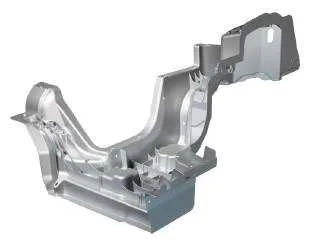
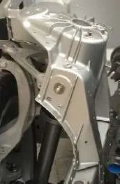
The automotive industry is under pressure to reduce CO2 emissions, primarily through improved fuel efficiency. A key strategy is lightweighting, replacing heavier steel components with lighter aluminum castings (Figure 1.1, Figure 1.2). Aluminum can be introduced in various forms, including castings, which offer weight savings and functional integration advantages (Figure 1.3). Specific BIW sections, like shock towers, are good candidates for aluminum die casting (Figure 1.4).
Status of previous research:
Several automotive OEMs already use aluminum castings for structural body parts, typically using Al-Si alloys and processes like High Pressure Die Casting (HPDC) (Figure 2.1, Figure 2.2, Figure 2.3, Figure 2.4). HPDC is a dominant process for light metal casting due to its short cycle time (Table 2.1). Semi-solid casting, including Thixocasting and Rheocasting (Figure 2.13), offers advantages like reduced porosity (Figure 2.12). The RheoMetalTM process is a specific rheocasting method with unique benefits (Figure 2.18).
Need for research:
While aluminum castings offer weight reduction, they can be more expensive than steel components, primarily due to the higher cost of aluminum alloys. This research addresses the need to develop a cost-efficient process route for mass-producing thin-walled structural aluminum castings.
4. Research purpose and research question:
Research purpose:
The main aim of this thesis is to develop a cost-efficient process route for the mass production (1,000,000 – 2,000,000 parts) of thin-walled structural aluminum body castings.
Core research:
The core research involves identifying the factors with the highest influence on the cost of a thin-walled structural aluminum body casting (2020 Ford explorer’s shock tower).
5. Research methodology
The research approach involved a series of milestones (Figure 1.5):
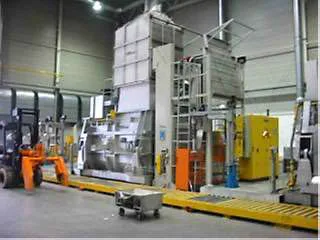
- Cost Calculation Study: A detailed cost analysis was performed to identify key cost drivers in producing a 2020 Ford Explorer shock tower (Figure 3.1). Factors considered included HPDC machine type, alloy and heat treatment, vacuum application, die life, and casting process (Table 0.1, Table 3.1). A calculation tool, originally from Bühler AG, was used (Figure 3.2).
- Defining Suitable Test Alloys: Alloys were selected based on their potential to meet mechanical and joining requirements without expensive heat treatments (Table 0.2). Suitability for both HPDC and RheoMetalTM processes was considered. A new alloy, MYFORD, was developed to improve the feeding efficiency and rheocastability of the standard AlMg4Fe2 alloy (Figure 0.1).
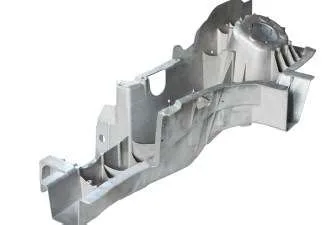
- Production of Plates and Parts: Test geometries (plates and a heatsink part resembling the shock tower) were produced using both HPDC and RheoMetalTM processes at different suppliers (Table 0.3, Figure 4.3, Figure 4.4, Figure 4.5, Figure 4.7, Figure 4.10, Figure 4.11, Figure 4.12, Figure 4.13).
- Characterization and Evaluation: A series of tests and analyses were conducted (Table 0.4):
- Uniaxial tensile tests (Figure 4.18, Figure 4.19, Figure 4.20, Figure 4.21, Figure 4.23, Figure 4.24, Figure 4.25).
- 3-point bending tests (Figure 4.26, Figure 4.27, Figure 4.28, Figure 4.29).
- Density measurements (Figure 4.30).
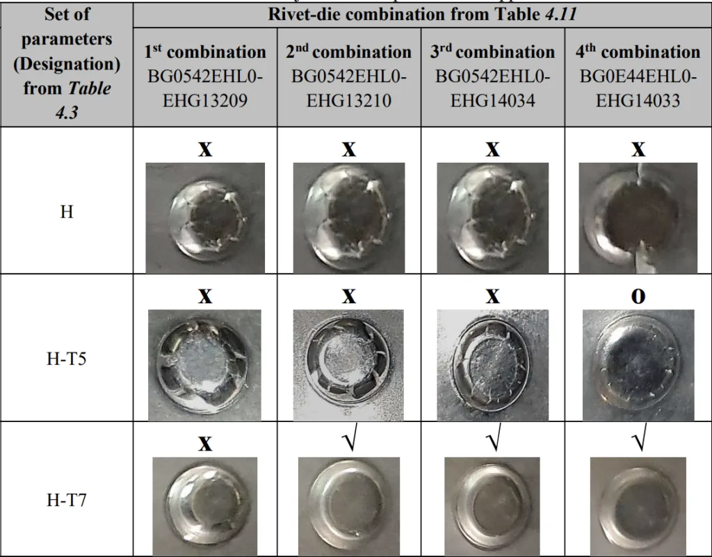
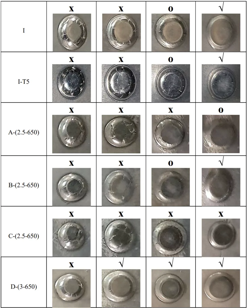
- Self-piercing riveting (SPR) analysis (Figure 4.31, Figure 4.32, Figure 4.33, Figure 4.34, Figure 4.35, Figure 4.36, Figure 4.37, Figure 4.38).
- Microstructural analysis (Figure 4.39, Figure 4.40).
- SEM-EDS Analysis.
- Optical Emission spectroscopy.
- Guidelines for testing:
- The best location within the plates (Figure 4.41, Table 4.13)
- The symmetry of the plates (Figure 4.42)
- The relevant tensile test sample (Figure 4.43)
- The suitable orientation of the samples (Figure 4.44)
- The consistency of the casting process (Figure 4.45)
6. Key research results:
Key research results and presented data analysis:
- Cost Calculation Study: Heat treatment had the greatest impact on cost. The RheoMetalTM process showed potential for cost reduction, mainly due to its positive impact on die life (Table 3.3, Figure 3.4).
- HPDC Trials:
- Optimum HPDC process parameters were derived (Table 4.3, Table 5.1).
- AlMg4Fe2, MYFORD, and AlSi10MnMg-T7 met the mechanical requirements of the shock tower (Table 0.5, Table 5.6).
- These alloys also showed the best crash resistance potential and rivetability (Table 0.5).
- RheoMetalTM Trials:
- MYFORD delivered the best performance (Table 0.6, Table 4.5).
- RheoMetalTM process showed lower crash resistance potential compared to HPDC in the tested geometries (Table 0.6).
- Optimum process parameters were investigated (Table 6.1).
The most often-used die casting process is high pressure die casting (HPDC), which accounts
for approximately half of the overall light metal casting production (15). This, together with its
short cycle time, makes it a more attractive die casting process for the large volume production
of automotive body parts.
List of figure names:
- Figure 0.1: The JMatPro® simulations of the AlMg4FeX alloy with (a) X= 1.3% Fe and (b) X= 0.5% Fe (MYFORD).
- Figure 0.2: (a) The geometrical dimensions and (b) the thickness distribution (mm) of the 2020 Ford explorer aluminium shock tower.
- Figure 1.1: The current and future CO2 emission requirements for passenger cars (8).
- Figure 1.4: MMLV BIW design (12).
- Figure 1.5: The thesis milestones.
- Figure 2.1: Porsche 911- rear Longitudinal rail (Magna BDW technologies Soest GmbH).
- Figure 2.2: Jaguar XE/XF- Front shock tower (Magna BDW technologies Soest GmbH).
- Figure 2.3: Range rover- rear longitudinal frame (Magna BDW technologies Soest GmbH).
- Figure 2.4: The casting processes and the extent of their implementation in the automotive industry (13).
- Figure 2.5: The properties of the different casting methods (14).
- Figure 2.6: The different die-casting processes (15).
- Figure 2.7: (a) The effect of the gate velocity on the pore fraction and on (b) the mechanical properties (modified from (18)).
- Figure 2.8: The effect of the intensification pressure (IP) on (a) the porosity content and (b) the macrostructures of the high pressure die castings (modified from (21)).
- Figure 2.9: The concept of vacuum assisted die casting (22).
- Figure 2.10: The structure of the cold flake and its accompanying oxide layer (28).
- Figure 2.11: Shear bands in a HPDC test bar of an AlSi7Mg0.3 alloy (30).
- Figure 2.12:The typical die casting microstructures of the AlSi7 alloy that are formed using (a) the conventional liquid die casting process and (b) the semi-solid casting process (38).
- Figure 2.13: Different technologies for the semi-solid casting of the metallic alloys (modified from (40)).
- Figure 2.14: The main stages in thixocasting (41).
- Figure 2.15: Different techniques of melt stirring: (a) mechanical stirring, (b) passive stirring, (c) electromagnetic vertical stirring, (d) electromagnetic horizontal stirring (39).
- Figure 2.16: A typical thixocasting microstructure of the A356 alloy with regions of entrapped liquid (44).
- Figure 2.17: Illustration of the process steps in rheocasting (45).
- Figure 2.18: The slurry preparation in the RheoMetalTM process: Step 1) pouring the melt into the ladle, Step 2) inserting the rotating enthalpy exchange material (EEM) into the melt, step 3) the semi-solid slurry is formed (48).
- Figure 2.19: An illustration of the Semi-Solid Rheocasting process (S.S.R.TM) (41).
- Figure 2.20: A schematic diagram of the RheoMetalTM process (source: RheoMetal AB).
- Figure 2.21: (a) Dock cleat (b) LED housing and (c) Brackets for the telecom industry.
- Figure 2.22: The influence of the rotation speed on the (a) average size of the 𝛼1-Al phase, (b) the fraction of the 𝛼1-Al phase, (c) the slurry formation time and the cooling rate.
- Figure 2.23: The influence of the melt superheat on the (a) average size of the 𝛼1-Al phase, (b) the fraction of the 𝛼1-Al phase, (c) the slurry formation time and the cooling rate.
- Figure 2.24: The combined influence of the melt superheat and the EEM amount on (a) the average size of the 𝛼1-Al phase, (b) the fraction of the 𝛼1-Al phase, (c) the slurry formation time and the cooling rate.
- Figure 2.25: (a) Eutectic rich bands and (b) porosity bands that can develop in Rheocast parts (54).
- Figure 2.26: The microstructure of a rheocast radio filter (a) near the gate and (b) near the vent (49).
- Figure 2.27: The hypoeutectic Al-Si phase diagram (61).
- Figure 2.28 : The time - temperature graphs of the different heat treatments.
- Figure 3.1: An aluminium shock tower (red) in the 2020 Ford explorer’s body.
- Figure 3.2: The outline of the ‘expenses of investment’s section in the calculation tool.
- Figure 3.4: The cost per part breakdown chart according to the RheoMetalTM and the HPDC process scenarios.
- Figure 4.1: (a) The geometrical dimensions and (b) the thickness distribution (mm) of the 2020 Ford explorer aluminium shock tower.
- Figure 4.2: The experimental approach.
- Figure 4.3: The HPDC setup consisting of (a) the holding electric resistance furnace, (b) the shot sleeve, ladle & robot arm and (c) the vacuum assisted die.
- Figure 4.4: The dimensions of the plates from supplier 1.
- Figure 4.5: The die cavity’s design for the HPDC trials at supplier 1.
- Figure 4.6: The dimensions of the plates from supplier 2.
- Figure 4.7: The setup consisting of (a) the induction furnace, (b) the EEM production station and (c) the slurry production station.
- Figure 4.8: (a) The EEM’s height before adjustment (casted EEM), (b) the sawing machine and (c) the EEM’s height after adjustment (hEEM).
- Figure 4.9: The slurry making process.
- Figure 4.10: The die cavity’s design for the RheoMetalTM casting trials at supplier 1.
- Figure 4.11: (a) The top view, (b) the bottom view and the (c) side view of the part.
- Figure 4.12: (a) The 800-ton HPDC machine, (b) the die and the second robot arm and the (c) moving tray.
- Figure 4.13: The different pre-steps for the production of the semi-solid slurry.
- Figure 4.14: The phase diagram of the standard AlMg4Fe2 alloy with 1.5-1.7%Fe and 4.5% Mg (modified from (77)).
- Figure 4.15: The suggested enhancement to the standard AlMg4Fe2 alloy, as demonstrated by the circle and the arrow (modified from (77)).
- Figure 4.16: The JMatPro® simulation for the Al-Mg-Fe alloy with a 1.3%Fe.
- Figure 4.17: The JMatPro® simulation for the MYFORD alloy.
- Figure 4.18: The exact geometrical dimensions of the Type E sample in mm (6).
- Figure 4.19: The exact geometrical dimensions of the mini samples in mm.
- Figure 4.20: A 3D model of the supplier 1 plate and the tensile testing samples.
- Figure 4.21: (a) The initial dimension, (b) the extra 1 mm and (c) the final dimension of the (i) mini sample and the (ii) Type E sample in mm.
- Figure 4.22: The top and side views of a mini sample (a)before and (b)after preparation.
- Figure 4.23: The extracted tensile test samples from the (a) supplier 1 plates, (b) supplier 2 plates and (c) supplier 3 parts.
- Figure 4.24: The tensile test setup for the mini and the Type E samples.
- Figure 4.25: The different test speeds during tensile testing.
- Figure 4.26: (a) The setup of the 3-point bending test and (b) the important dimensions (4).
- Figure 4.27: The dimensions of the bending test samples.
- Figure 4.28: The location of the 3-point bending test samples in the (a) supplier 1 plates, (b) supplier 2 plates and (c) supplier 3 parts.
- Figure 4.29: (a) An example of a bending angle and (b) the bending angle’s measuring tool.
- Figure 4.30: The setup for the density measurement trials.
- Figure 4.31: The positions of the SPR samples in (a) the supplier 1 plates (thickness = 3.1 mm) and (b) the supplier 2 plates (thickness = 2.65 mm).
- Figure 4.32: An example of a good SPR joint (86).
- Figure 4.33: The flat die design (88).
- Figure 4.34: Henrob SPR setup for manual trials.
- Figure 4.35: (a) The joint making using the SPR process (86) and (b) the connected structures.
- Figure 4.36: An example of the (a) circumferential cracks, (b) deep radial cracks and (c) light radial cracks.
- Figure 4.37: The 25 mm * 100 mm lap shear test samples.
- Figure 4.38: The SPR trials on the parts from supplier 3.
- Figure 4.39: The location of the extracted samples from (a) the supplier 1 plates, (b) the supplier 2 plates and (c) the supplier 3 parts.
- Figure 4.40: An example of a hot mounted sample.
- Figure 4.41: The positions a, b and c in the supplier 1 plates.
- Figure 4.42: (a) The total elongation values (%) of the different samples and (b) their respective positions in the plates. (Designation from Table 4.3, P54)
- Figure 4.43: (a) The total elongation values (%) of the different sample types and (b) the outline of the samples in one of the investigated plates. (Designation from Table 4.3, P54)
- Figure 4.44: (a) The effect of the sample orientation on the total elongation values (%), (b) the positions of the longitudinal and perpendicular samples in respect to each other, (c) the location of the extracted longitudinal samples and (d) the location of the extracted perpendicular samples. (Designation from Table 4.3, P54)
- Figure 4.45: The consistency of the HPDC process at supplier 1 using the (a) Type E samples and the (b) mini tensile test samples. (Designation from Table 4.3, P54)
- Figure 5.1: The influence of the melt flow velocity on the total elongation (%) of AlMg4Fe2. (Designations from Table 4.3, P54)
- Figure 5.2: The influence of the melt flow velocity on the total elongation (%) of (a) AlSi7Mg0.3 and (b) AlMg6Si2MnZr. (Designations from Table 4.3, P54)
- Figure 5.3: The influence of the melt flow velocity on the total elongation (%) of AlMg5Si2Mn. (Designations from Table 4.3, P54)
- Figure 5.4: The influence of the intensification pressure on the total elongation (%) of AlMg4Fe2. (Designations from Table 4.3, P54)
- Figure 5.5: The comparison between the different HPDC alloys and alloy-heat treatment combinations in terms of their (a) Rp0.2 values (MPa), (c) Rm values (MPa) and (c) total elongation values (%). (Designations from Table 4.3, P54)
- Figure 5.6: The comparison between the different HPDC alloys in terms of their (a) Rp0.2 values (MPa), (c) Rm values (MPa) and (c) total elongation values (%). (Designations from Table 4.9, P65)
- Figure 5.7: The force-displacement chart of the Al-Si alloys and alloy-heat treatment combinations. (Designations from Table 4.3, P54)
- Figure 5.8: The energy-displacement diagram of the Al-Si alloys and alloy-heat treatment combinations. (Designations from Table 4.3, P54)
- Figure 5.9: The simulated force-displacement chart of the Al-Si alloys and alloy-heat treatment combinations. (Designations from Table 4.3, P54)
- Figure 5.10 : The simulated energy-displacement chart of the Al-Si alloys and alloy-heat treatment combinations. (Designations from Table 4.3, P54)
- Figure 5.11: The force-displacement chart of all the HPDC alloys and alloy-heat treatment combinations that were used for the casting of the plates. (Designations from Table 4.3, P54)
- Figure 5.12: The energy-displacement chart of all the HPDC alloys and alloy-heat treatment combinations that were used for the casting of the plates. (Designations from Table 4.3, P54)
- Figure 5.13: The force-displacement chart of the HPDC alloys that were used at supplier 3. (Designations from Table 4.9, P65)
- Figure 5.14: The energy-displacement chart of the HPDC alloys that were used at supplier 3. (Designations from Table 4.9, P65)
- Figure 5.15: The force-displacement chart for the HPDC alloys and alloy-heat treatment combinations that belonged to the groups (b) and (c). (Designations from Table 4.3, P54)
- Figure 6.1: The influence of the intensification pressure on the total elongation (%) of the AlMg4Fe2 alloy. (Designations from Table 4.5, P58)
- Figure 6.2: The comparison between the different RheoMetalTM alloys in terms of their (a) Rp0.2 values (MPa), (c) Rm values (MPa) and (c) total elongation values (%). (Designations from Table 4.5, P58)
- Figure 6.3: The comparison between the different RheoMetalTM alloys in terms of their (a) Rp0.2 values (MPa), (c) Rm values (MPa) and (c) total elongation values (%). (Designations from Table 4.9, P65)
- Figure 6.4: The force-displacement chart for the RheoMetalTM alloys that were used for the casting of the plates at supplier 1. (Designations from Table 4.5, P58)
- Figure 6.5: The energy-displacement chart for the RheoMetalTM alloys that were used for the casting of the plates at supplier 1. (Designations from Table 4.5, P58)
- Figure 6.6: The force-displacement chart of the RheoMetalTM alloys that were used at supplier 3. (Designations from Table 4.9, P65)
- Figure 6.7: The energy-displacement chart of the RheoMetalTM alloys that were used at supplier 3. (Designations from Table 4.9, P65)
- Figure 6.8:The force-displacement chart for D-(50-4.63-575-1000)-R. (Designation from Table 4.5, P58)
- Figure 7.1: The shrinkage porosities in the microstructures of (a) AlMg5Si2Mn (B-(3.5-650)) and (b) AlMg6Si2MnZr (C-(3.5-650)). (Designations from Table 4.3, P54)
- Figure 7.2: The 500x microstructural images of (a) AlSi10MnMg-F and (b) AlSi10MnMg-T7. (Designations from Table 4.3, P54)
- Figure 7.3: Dislocations overcoming a precipitate a) by shearing or b) by looping (Orowan mechanism) and c) the effect of the dislocations passing mechanism on the total yield strength of the alloy (65).
- Figure 7.4: (a) The Rp0.2 values (MPa), (b) the Rm values (MPa) and (c) the total elongation values (%) of AlSi10MnMg-T7. (Designations from Table 4.3, P54)
- Figure 7.5: The 200x microstructural images of (a) AlSi10MnMg (H) and of (b) AlMg4Fe2 (D-(3-650)). (Designations from Table 4.3, P54)
- Figure 7.6: The 500x microstructural images of (a) AlMg4Fe2 (F-740C) and of (b) MYFORD (G-755C). (Designations from Table 4.9, P65)
- Figure 7.7: The total elongation (%) chart for the investigated RheoMetalTM alloys at supplier 1. (Designation from Table 4.5, P58)
- Figure 7.8: The 500x microstructural images of (a) the AlMg4Fe2 alloy (F-750R-1100-30C) and of (b) the MYFORD alloy (G-755R-1100-30C). (Designations from Table 4.9, P65)
- Figure 7.9: The crash resistance potentials of the RheoMetalTM parts (red) and the parts produced by HPDC (black).
7. Conclusion:
Summary of key findings:
- Cost Drivers: Heat treatment and die life are major cost factors.
- HPDC: AlMg4Fe2, MYFORD, and AlSi10MnMg-T7 met the mechanical requirements, with the first two offering the advantage of no heat treatment. MYFORD and AlSi10MnMg-T7 showed the best crash resistance and rivetability.
- RheoMetalTM: MYFORD performed best. RheoMetalTM parts showed potentially lower crash resistance than HPDC parts (in the tested configuration).
- MYFORD Alloy: Demonstrated superior performance in both HPDC and RheoMetalTM processes, particularly in terms of rivetability and crash resistance.
The MYFORD alloy is identified as the most suitable choice for cost-efficient mass production of the 2020 Ford Explorer shock tower, particularly when used with the HPDC process. It offers comparable performance to the currently used AlSi10MnMg-T7 alloy but without requiring heat treatment. It also shows potential for use with the RheoMetalTM process. The RheoMetalTM process, while showing promise for cost reduction through increased die life, may require further optimization for thin-walled structural components.
8. References:
- [1] Rio Tinto, “Aluminium: Your guide to automotive innovation,” 2019. [Online]. Available: https://www.riotinto.com/documents/Aluminium_Automotive_innovation_brochure.pdf. [Accessed: 11-Nov-2019].
- [2] Aluminium Rheinfelden GmbH, “Handbook- Primary aluminum casting alloys,” 2017. [Online]. Available: http://rheinfelden-alloys.eu/wp-content/uploads/2017/12/LeporelloCastingAlloys_12-2017_Singular_pages.pdf. [Accessed: 12-Sep-2019].
- [3] Stena Aluminium, “Aluminium alloy EN AB-42000,” [Online]. Available: https://www.stenaaluminium.com/siteassets/document/product-sheets/eng-en-ab-42000.pdf. [Accessed: 30-Oct-2019].
- [4] Verband der Automobilindustrie (VDA), “VDA 238-100 : Plate bending test for metallic materials,” Berlin : VDA, 2010.
- [5] International Organization for Standardization (ISO), “ISO 6892-1. METALLIC MATERIALS - TENSILE TESTING - Part 1 : Method of test at room temperature,” Geneva : ISO, 2016.
- [6] Deutsches Institut für Normung (DIN), “DIN 50125: Prüfung metallischer Werkstoffe- Zugproben,” Berlin : Beuth Verlag, 2016.
- [7] O. Hoegh-Guldberg et al., “Impacts of 1.5°C Global Warming on Natural and Human Systems,” in Global Warming of 1.5°C. An IPCC Special Report on the impacts of global warming of 1.5°C above pre-industrial levels and related global greenhouse gas emission pathways, in the context of strengthening the global response to the threat of climate change, V. Masson-Delmotte et al., Eds. Geneva : The intergovernmental panel on climate change (ipcc), 2018.
- [8] Z. Yang and A. Bandivadekar, “2017 Global update : Light-duty vehicle greenhouse gas and fuel economy standards,” 2017. [Online]. Available: https://www.theicct.org/sites/default/files/publications/2017-Global-LDV-Standards-Update_ICCT-Report_23062017_vF.pdf. [Accessed: 29-May-2018].
- [9] Ducker Worldwide LLC, “2015 North American Light Vehicle Aluminum Content Study,” 2014. [Online]. Available: https://www.autonews.com/assets/PDF/CA95065611.PDF. [Accessed: 07-Nov-2019].
- [10] M. Goede, et al., “Super Light Car—lightweight construction thanks to a multi-material design and function integration,” European Transport Research Review, vol. 1, no. 1, pp. 5–10, 2009.
- [11] NADCA Design, “Die Casting vs Metal Extrusion,” NADCA Design. [Online]. Available: https://www.diecastingdesign.org/metal-extrusions. [Accessed: 11-Nov-2019].
- [12] G. Yuksel, et al., “MMLV : NVH Sound Package Development and Full Vehicle testing, SAE Technical Paper 2015-01-1615,” SAE International, 2015.
- [13] European Aluminum Association, “The Aluminum Automotive manual, Manufacturing casting methods,” 2002. [Online]. Available: https://www.european-aluminium.eu/media/1526/aam-manufacturing-1-casting-methods.pdf. [Accessed: 23-May-2019].
- [14] The American Foundry Society Technical Dept, “Aluminium Alloys,” Engineered casting solutions, vol. 8, no. 4, pp. 30–34, 2006.
- [15] AZoM, “Aluminium Casting Techniques - Sand Casting and Die Casting Processes,” 2002. [Online]. Available: https://www.azom.com/article.aspx?ArticleID=1392. [Accessed: 04-Jul-2018].
- [16] Foundry Lexicon, “Foundry Lexicon,” Foundry Lexicon. [Online]. Available: https://www.giessereilexikon.com/en/foundry-lexicon/Encyclopedia. [Accessed: 24-Apr-2019].
- [17] Robert Karban, “The effects of intensification pressure, gate velocity, and intermediate shot velocity on the internal quality of aluminum die castings,” PHD thesis, Purdue University, 2000.
- [18] D. R. Gunasegaram, B. R. Finnin, and F. B. Polivka, “Melt flow velocity in high pressure die casting : its effect of microstructure and mechanical properties in an Al-Si alloy,” Materials Science and Technology, vol. 23, no. 7, pp. 847–856, 2007.
- [19] E.A. Herman, “Gating Die Casting Dies,” Rosemont,IL : NADCA, 1996.
- [20] E. Fiorese, et al., “Influence of injection parameters on the porosity and tensile properties of high-pressure die cast Al–Si alloys : A review,” International Journal of metalcasting, vol. 1, no. 9, pp. 43–53, 2015.
- [21] S. Otarawanna, et al., “Feeding mechanisms in High-pressure die castings,” Metallurgical and Materials Transactions A, vol. 41, no. 7, pp. 1836–1846, 2010.
- [22] X.P. Niu, et al., “Vaccum assisted high pressure die casting of aluminium alloys,” Journal of Materials Processing Technology, vol. 105, no. 1–2, pp. 119–127, 2000.
- [23] S. SUN, B. Yuan, and M. Liu, “Effects of moulding sands and wall thickness on microstructure and mechanical properties of Sr-modified A356 Aluminum casting alloy,” Transactions of Nonferrous Metals Society of China, vol. 22, no. 8, pp. 1884–1890, 2012.
- [24] M.B. Djurdjevic and M. Grzincic, “The Effect of Major Alloying Elements on the size of secondary dendrite arm spacing in the As-cast Al-Si-Cu Alloys,” ARCHIEVES of FOUNDARY ENGINEERING, vol. 12, no. 1, pp. 19–24, 2012.
- [25] K. Radhakrishna and S. Seshan, “Dendritic arm spacing and mechanical properties of Aluminium Alloy castings,” Cast Metals, vol. 2, no. 1, pp. 34–38, 1989.
- [26] M. Hartlieb, “High Integrity Die Casting : A Holistic Approach To Improved Die Casting Quality,” [Online]. Available: http://www.visi-trak.com/pdf/High%20Integrity%20Die%20Casting%20-%20iMdc%20Dec%202013.pdf. [Accessed: 07-Nov-2019].
- [27] Niels Pasligh, “Hybride formschlüssige Strukturverbindungen in Leichtbaustrukturen aus Stahlblech und Aluminiumdruckguss,” Dissertation, Giesserei-Instiut der RWTH Aachen, 2011.
- [28] A. Ahamed and H. Kato, “Influence of Casting Defects on Tensile properties of ADC12 Aluminum Allo Die-Castings,” Materials Transactions, vol. 49, no. 7, pp. 1621–1628, 2008.
- [29] X. Cao and J. Campbell, “Oxide inclusion defects in Al-Si-Mg cast alloys,” Canadian Metallurgical Quarterly, vol. 44, no. 4, pp. 435–448, 2005.
- [30] C.M.Gourlay and A.K.Dahle, “Dilatant shear bands in solidifying metals,” Nature, vol. 445, no. 7123, pp. 70–73, 2007.
- [31] A. Ghosh, “Segregation in cast products,” SADHANA, vol. 26, no. 1–2, pp. 5–24, 2001.
- [32] S.P. Midson and A. Jackson, “A comparison of Thixocasting and Rheocasting,” in 67th World Foundry Congress (wfc06): Casting the Future, Harrogate, UK: Institute of Cast Metals Engineers, 2006, pp. 1081–1090.
- [33] S.P. Midson, L.E. Thornhill, and K. Young, “Feeding mechanisms in High-pressure die castings,” in Proc.5th Int.Conf. On Semi-Solid Processing of Alloys & Composites, Golden, Colorado: Colorado School of Mines, 1998. p. 181.
- [34] M. Jolly, “Prof. John Campbell’s Ten Rules for Making Relaible Castings,” JOM, vol. 57, no. 5, pp. 19–28, 2005.
- [35] Shahrooz Nafisi and Reza Ghomashchi, “Grain refining of conventional and semi-solid A356 Al-Si alloy,” Journal of Materials Processing Technology, vol. 174, pp. 371–383, 2006.
- [36] M.C. Flemings, “Behaviour of metal alloys in the semi-solid state,” Metallurgical Transactions A, vol. 22, no. 5, pp. 957–981, 1991.
- [37] D.G. McCartney, “Grain refining of aluminium and its alloys using inoculants,” International Material Reviews, vol. 13, no. 5, pp. 247–260, 1989.
- [38] A Pola, M Toci, P Kapronas, "Microstructure and properties of Semi-Solid Aluminum Alloys: A literature review", Metals. 2018, Vol.8,3, p.181.
- [39] H. Gerhard, et al., “Semi-solid Forming of Aluminium and Steel-Introduction and overview,” in Thixoforming: Semi-Solid Metal Processing, H. Gerhard and R Kopp, Eds. Weinheim : WILEY-VCH Verlag GmbH & Co. KGaA, 2009.
- [40] F. Czerwinski, “The basics of modern semi-solid metal processing,” JOM, vol. 58, no. 6, pp. 17–20, 2006.
- [41] James A Yurko, Raul A. Martinez, and Merton C.Flemings, "The use of Semi Solid Rheocasting (SSR) for Aluminum automotive castings." SAE paper 2003-01-0433., 2003.
- [42] Z. Fan, “Semisolid metal processing,” International Materials Reviews, vol. 47, no. 2, pp. 49–85, 2002.
- [43] D. H. Kirkwood, et al., Semi-Solid Processing of Alloys. Berlin, Heidelberg: Springer, 2010.
- [44] M. Modigell, P. Annalisa, and T. Marialaura, “Rheological Characterization of Semi-Solid Metals: A Review,” Metals, vol. 8, no. 4, pp. 245–268, 2018.
- [45] T. Basner, “Rheocasting of semi solid A357 Aluminum,” SAE paper :2000-01-0059, SAE International, 2000.
- [46] S.P. Midson, “Rheocasting processes for Semi-Solid Casting of Aluminium Alloys,” Die Casting Engineer, vol. 1, pp. 48–51, 2006.
- [47] Hong C.P. and Kim J.M., “Development of Advanced Rheocasting Process and its applications,” Solid State Phenomena, Vols. 116-117, pp. 44–53, 2006.
- [48] Patent: WO/2006/062, 482. A method of and a device for producing a liquid-solid metal composition. Filling date: 2006, Inventors: Wessen, M; Cao, H.
- [49] Mostafa Payandeh, “Rheocasting of Aluminium Alloys, Process and components characteristics,” PhD thesis, Jönköping university, 2016.
- [50] H.Cao, M.Wessén, and O.Granath, “Effect of injection velocity on porosity formation in Al rheocast component using Rheometal process,” International Journal of Cast Metals Research, vol. 23, no. 3, pp. 158–163, 2010.
- [51] J. Lee, H. Seok, and H. Lee, “Effect of the Gate Geometry and the Injection Speed on the Flow,” Metals and Materials International, vol. 9, no. 4, pp. 351–357, 2003.
- [52] O.Granath, M.Wessen and H.Cao, "Determining the effect of the slurry process parameters on semisolid A356 alloy microstructures produced by Rheometal process", International Journal of Cast Metals Research, vol. 21, no.5, pp. 349-356, 2008.
- [53] M. Bladh, M. Wessen, and A.K. Dahle, “Shear band formation in shaped Rheocast Aluminium component at various plunger velocities,” Trans.Nonferrous Met. Soc. China, vol. 20, no. 9, pp. 1749–1755, 2010.
- [54] M. Payandeh, A. Jarfors, and M. Wessen, “Influence of microstructural inhomogenity on fracture behaviour in SSM-HPDC Al-Si-Cu-Fe component with low Si content,” Solid state phenomena, Vols. 216-217, pp. 67–74.
- [55] Baiwei Zhu, “On the influence of Si on Anodising and Mechanical properties of Cast Aluminium Alloys,” Licentiate thesis, Jönköping University, 2017.
- [56] S. Hegde and K.N. Prabhu, “Modification of eutectic silicon in Al-Si alloys,” Journal of Materials science, vol. 43, no. 9, pp. 3009–3027, 2008.
- [57] X. Zhu, et al., “The effects of varying Mg and Si levels on the microstructural inhomogenity and eutectic Mg2Si morphology in die-cast Al-Mg-Si alloys,” Journal of Materials Science, vol. 54, no. 7, pp. 5773–5787, 2019.
- [58] W. Yuan and Z. Liang, “Effect of Zr addition on properties of Al-Mg-Si aluminum alloy used for all aluminium alloy conductor,” Materials and Design, vol. 32, no. 8, pp. 4195–4200, 2011.
- [59] S. Ji, et al., “Effect of iron on the microstructure and mechanical property of Al-Mg-Si-Mn and Al-Mg-Si diecast alloys,” Materials Science and Engineering A, vol. 564, pp. 130–139, 2013.
- [60] J.Y. Hwang, H.W. Doty, and M.J. Kaufman, “The effects of Mn additions on the microstructure and mechanical properties of Al-Si-Cu casting alloys,” Materials Science and Engineering A, vol. 488, no. 1–2, pp. 496–504, 2008.
- [61] J.L. Murray and A.J. McAlister, “,” Bulletin of Alloy Phase Diagrams, vol. 5, no. 1, pp. 86–112, 1984.
- [62] G.T. Zeru, B.R. Mose, and S.M. Mutuli, “The fluidity of a Model Recycle-Friendly Al-Si Cats Alloy for Automotive Engine Cylinder Head Application,” International Journal of Engineering Research & Technology (IJERT), vol. 3, no. 8, 2014.
- [63] G. Timelli and F. Bonollo, “Fluidity of aluminium die casting alloys,” International Journal Of Cast Metals Research, vol. 20, no. 6, pp. 304–311, 2007.
- [64] M Gwózdz and K Kwapisz, "Influence of ageing process on the microstructure and mechanical properties of aluminium-silicon cast alloys - Al-9%Si-3%Cu and Al-9%Si-0.4%Mg", Jönköping University, Bachelor thesis, 2008.
- [65] A.M.A. Mohamed and F.H. Samuel, “A Review on the Heat Treatment of Al-Si-Cu/Mg Casting Alloys,” in Heat treatment - Conventional and novel applications, IntechOpen, 2012, pp. 55–72.
- [66] L Katgerman and D Eskin, "Hardening, annealing and aging," in Handbook of Aluminum: Vol. 1: Physical Metallurgy and Processes, G.E Totten and D.S Mackenzie, Eds. New York : Marcel Dekker, Inc, 2003, pp. 269–271.
- [67] Bühler AG, “Carat. The solution with highest value creation for sophisticated parts,” 2018. [Online]. Available: http://www.buhlergroup.com/northamerica/en/downloads/Brochure_Carat_EN_2018.pdf. [Accessed: 24-May-2019].
- [68] Tecnopres, “Hydraulic 4 columns Trimming presses,” 2018. [Online]. Available: https://www.tecnopres.it/wp-content/uploads/2018/06/caratteristiche-tecniche-presse-KZP.pdf. [Accessed: 24-May-2019].
- [69] KMA Umwelttechnik GmbH, “KMA press release GIFA 2007,” 2007. [Online]. Available: https://www.foundry-planet.com/fileadmin/redakteur/Material/KMAforGIFA2007.pdf. [Accessed: 08-Nov-2019].
- [70] STØTEK Inc, “Holding Furnace (STE) / (STET),” STØTEK Inc. [Online]. Available: http://stotek.com/our-products/ste-stet-holding-furnace/. [Accessed: 27-Jul-2018].
- [71] The London Metal Exchange, “LME Aluminum alloy,” The London Metal Exchange, 2019. [Online]. Available: https://www.lme.com/Metals/Non-ferrous/Aluminium-Alloy#tabIndex=2. [Accessed: 24-Jan-2019].
- [72] H. Kaufmann and P.J. Uggowitzer, Metallurgy and Processing of High Integrity Light Metal Pressure Castings. Berlin : SCHIELE & SCHÖN, 2014.
- [73] Q. Han, E.A. Kenik, and S. Viswanathan, “Die soldering in aluminium die casting,” Office of Scientific & Technical Information Technical Reports, 2000.
- [74] H.A. Abdulhadi, et al., “Thermal Fatigue of Die-Casting Dies: An Overview,” in MATEC Web of Conferences, ICMER 2015, 2016, vol. 74, p. 00032.
- [75] Visi-trak worldwide, LLC, “High-Q-Cast,” [Online]. Available: http://www.visi-trak.com/Media/High-Q-Cast-NADCA-2011.pdf. [Accessed: 23-Jul-2018].
- [76] S.P. Midson, R.B. Minkler, and H.G. Brucher, “Gating of Semi-Solid Aluminum Castings,” in Proc 6th Inter. Conf. on Semi-Solid Processing of Alloys and Composites, Turin, Italy, 2000, pp. 67–71.
- [77] Aluminium Rheinfelden GmbH, “Primary aluminum- HPDC alloys for Structural Casts in Vehicle Construction,” 2017. [Online]. Available: http://rheinfelden-alloys.eu/wp-content/uploads/2018/01/Handbook-Al-HPDC-Alloys-for-Structural-Casts_RHEINFELDEN-ALLOYS_2017_EN.pdf. [Accessed: 08-Nov-2019].
- [78] G.H. Gulliver, “The quantitative effect of rapid cooling upon the constitution of binary alloys,” J.Inst.Met., vol. 9, pp. 120–157, 1909.
- [79] E. Scheil, “Comments on the layer crystal formation,” Z.Metallkd., vol. 34, pp. 70–72, 1942.
- [80] ESAB, “ESAB knowledge center,” ESAB. [Online]. Available: http://www.esabna.com/us/en/education/blog/waterjet-cutting-process-basics.cfm. [Accessed: 24-May-2019].
- [81] Techni waterjet, “Waterjet advantages,” Techni waterjet, 2018. [Online]. Available: http://www.techniwaterjet.com/waterjet-advantages/. [Accessed: 24-May-2019].
- [82] SMU department of physics, “Mechanics laboratery manual - Archimedes’ Principle and Buoyancy,” SMU department of physics, 2002. [Online]. Available: http://www.physics.smu.edu/~scalise/mechmanual/archimedes/lab.html. [Accessed: 08-Mar-2019].
- [83] M. Abbas, G.R. St.Pierre, and C.E. Mobley, “Microporosity of Air Cast and Vacuum Cast Aluminium Alloys,” AFS Transactions, vol. 49, pp. 47–56, 1986.
- [84] X. He, I. Pearson, and K. Young, “Self-pierce riveting for sheet materials: State of the art,” Journal of Materials Processing Technology, vol. 199, no. 1–3, pp. 27–36, 2008.
- [85] D. Li, et al., “Self-piercing riveting- a review,” The International Journal of Advanced Manufacturing Technology, vol. 92, no. 5–8, pp. 1777–1824, 2017.
- [86] Atlas Copco Group, “Henrob self-pierce riveting,” [Online]. Available: https://www.atlascopco.com/content/dam/atlas-copco/industrial-technique/general/documents/brochures-leaflets/joining-solutions/henrob-self-pierce-riveting-intro-presentation.pdf. [Accessed: 06-Aug-2019].
- [87] —, “Henrob BG-Rivet,” [Online]. Available: https://www.atlascopco.com/content/dam/atlas-copco/industrial-technique/general/documents/brochures-leaflets/joining-solutions/bg-rivet-pdf.pdf. [Accessed: 07-Aug-2019].
- [88] —, “Henrob die catalogue,” [Online]. Available: https://www.atlascopco.com/content/dam/atlas-copco/industrial-technique/general/documents/brochures-leaflets/joining-solutions/henrob-die-catalog.pdf. [Accessed: 08-Nov-2019].
- [89] E.V. Stephens, “Mechanical strength of self-piercing riveting,” in Self-Piercing Riveting: Properties, Processes and Applications, A Chrysanthou and X Sun, Eds. Woodhead Publishing Limited, 2014.
- [90] D. Li, et al., “Influence of Die Profiles and Cracks on Joint Quality and Mechanical Strengths of High Strength Aluminium Alloy Joint,” Advanced Materials Research, vol. 548, pp. 398–405, 2012.
- [91] SCG polymer solutions incorporated, “SEM Analysis | SEM-EDS Analysis,” [Online]. Available: https://www.polymersolutions.com/capabilities/scanning-electron-microscopy-with-energy-dispersive-spectroscopy/. [Accessed: 20-Mar-2019].
- [92] Encyclopaedia Britannica, “Spectrochemical analysis,” Encyclopaedia Britannica. [Online]. Available: https://www.britannica.com/science/spectrochemical-analysis. [Accessed: 22-Jan-2019].
- [93] S. OTARAWANNA and A.K. DAHLE, “Casting of aluminium alloys,” in Fundemetals of Aluminium Metallurgy: Production, Processing and Applications, Roger Lumely, Ed. Woodhead Publishing Limited, 2011.
- [94] R. Porcaro, et al., “The behaviour of a self-piercing riveted connection under quasi-static loading conditions,” International Journal of solids and structures, vol. 43, no. 17, pp. 5110–5131, 2006.
- [95] J.M. Park, et al., “High-strength bulk Al-based bimodal ultrafine eutectic composite with enhanced plasticity,” Journal of Materials Research, vol. 24, no. 8, pp. 2605–2609, 2009.
- [96] Q.G. Wang, C.H. Caceres, and J.R. Griffiths, “Damage by Eutectic Particle Cracking in Aluminum Casting Alloys A356/357,” Metallurgical and Materials Transactions A, vol. 34, no. 12, pp. 2901–2912, 2003.
- [97] A. Verma, et al., “Influence of cooling rate on the Fe intermetallic formation in an AA6063 Al alloy,” Journal of Alloys and Compounds, vol. 555, pp. 274–282, 2013.
- [98] Bielomatik, “Minimal Quantity Lubrication (MQL) Systems in Metal Cutting,” [Online]. Available: https://www.bielomatik.com/fileadmin/Dokumente/EN/Schmiersysteme/Brochure_MQL_EN_0316KL.pdf. [Accessed: 25-Oct-2019].
- [99] I. Vicario, et al., “Development of high pressure die casting dies with internal refrigeration and sensors with reinforced cast steels,” International Journal of Manufacturing Engineering, vol. 2014, p. Article ID 287986, 2014.
- [100] L. Kucharikova, et al., “Role of Chemical Composition in Corrosion of Aluminum Alloys,” Metals, vol. 8, no. 8, pp. 581–593, 2018.
9. Copyright:
- This material is a paper by "Mohamed Youssef Ahmed Youssef": Based on "A cost-efficient process route for the mass production of thin-walled structural aluminum body castings".
- Source of paper: 10.18154/RWTH-2021-03555
This material was created to introduce the above paper, and unauthorized use for commercial purposes is prohibited. Copyright © 2025 CASTMAN. All rights reserved.