This introduction paper is based on the paper "On determining the critical velocity in the high-pressure die casting machine's shot sleeve using CFD" published by "Preprint submitted to Elsevier".
![Figure 2: Impact of increasing plunger propagation according to [1]. The velocity increases
from the left to the right picture.](https://castman.co.kr/wp-content/uploads/image-2412.webp)
1. Overview:
- Title: On determining the critical velocity in the high-pressure die casting machine's shot sleeve using CFD
- Author: S. Kohlstädt, M. Vynnycky, S. Goeke, A. Gebauer-Teichmann
- Year of publication: 2019
- Journal/academic society of publication: Preprint submitted to Elsevier
- Keywords: compressible two-phase flow, fluid-structure interaction, high-pressure die casting, shot sleeve, critical velocity
2. Abstract:
This paper investigates the critical plunger velocity in high-pressure die casting during the slow phase of the piston motion and how it can be determined with CFD methods in open source software. The melt-air system is modeled via an Eulerian volume-of-fluid approach treating the air as a compressible perfect gas. The turbulence is treated via a RANS approach using the Menter SST k-ω model. Two different strategies for mesh motion are presented and compared against each other. The solver is validated via analytical models and empirical data. A method is then presented to determine the optimal velocity using a 2D mesh As a second step, it is then being discussed how those results are in line with the results obtained for real world 3D geometries and simulating also the ingate system of the die.
3. Introduction:
High-pressure die casting (HPDC) is an important process for manufacturing high volume and low cost automotive components, such as automatic transmission housings and gear box components [1-4]. Liquid metal, generally aluminium or magnesium, is poured into a shot sleeve chamber and further on injected through complex gate and runner systems and into the die at high speed, typically between 50 and 100 ms⁻¹, and under very high pressures up to 100 MPa. The normal high-pressure die casting process typically consists of three phases. These phases are shown in the following figure (figure 1 shows these phases. They are from left to right: pre-filling, die-filling (the shot), dwell-pressure). The content of this paper will evolve around the processes during the first phase only.
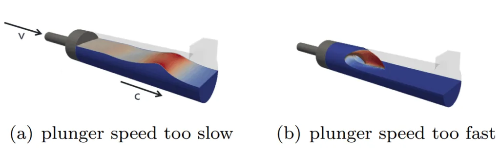
One aspect of this process are the flow processes that take part in the shot-sleeve of the high-pressure die casting machine. For each combination of piston diameter, melt height in the chamber and chamber length there is exactly one critical velocity that can be determined analytically [5, 6] or measured experimentally [7]. Faura et al. also defined the optimal acceleration parameters for reaching that velocity [6]. In order to achieve a sound casting process the plunger speed and its acceleration profile have to be selected carefully. Figure 2 illustrates this claim. The air-melt interface, i.e. the wave separates from the plunger an propagates freely inside the chamber if the plunger operates below the critical velocity. This is to be avoided as is may entrap air behind the ultimate melt front inside the casting. The two extrema are further shown in figure 3. Figure 3(a) shows a process setup where the plunger speed is far lower than the speed that the accumulating wave in the chamber naturally wants to propagate with. Figure 3(b) shows the other extremum where the plunger propagates too fast, resulting in a crashing of the wave. These figures indicate that there is only one good velocity for each melt height and shot-sleeve diameter combination.
4. Summary of the study:
Background of the research topic:
The high-pressure die casting (HPDC) process involves a critical first phase where the plunger pushes molten metal through the shot sleeve. The plunger velocity during this "slow phase" significantly impacts air entrapment and final casting quality. Determining the "critical velocity" – the optimal plunger speed – is crucial for minimizing defects.
Status of previous research:
Previous research includes analytical models for determining critical velocity and wave dynamics in the shot sleeve [5, 6], experimental studies measuring this velocity [7], and work by Garber [29] on optimal velocity and filling degrees. CFD simulations, such as those by Korti and Aboudi [21], have also been used to study melt/air interface dynamics.
Purpose of the study:
This paper aims to investigate the critical plunger velocity in HPDC during the slow phase using CFD methods with open-source software (OpenFOAM). The objectives include:
- Developing and validating a CFD model for the two-phase (melt-air) flow in the shot sleeve.
- Comparing different mesh motion strategies for handling the moving plunger.
- Determining the optimal plunger velocity using a 2D mesh through parameter studies.
- Discussing the alignment of 2D results with those from real-world 3D geometries, including the ingate system.
Core study:
The core of the study involves:
- Modeling the melt-air system using an Eulerian volume-of-fluid (VOF) approach, treating air as a compressible perfect gas and turbulence with a RANS Menter SST k-ω model.
- Implementing and comparing two mesh motion strategies: mesh compressing and layer addition/removal, with a preference for the latter.
- Validating the developed solver against analytical models (e.g., Reikher and Barkhudarov [27], shallow-water equations [28]) and existing CFD data [21].
- Conducting parameter studies on a 2D shot sleeve model to identify the relationship between plunger velocity and trapped air, thereby determining the optimal velocity range.
- Applying the validated solver to a 3D industrial shot sleeve geometry (EA211 crank case) to assess its performance and confirm the findings in a more realistic scenario.
5. Research Methodology
Research Design:
The research employed a computational fluid dynamics (CFD) simulation approach. The study involved modeling the two-phase (molten metal and air) compressible flow within the HPDC shot sleeve, incorporating a moving plunger. The research design included:
- Development of a CFD model using OpenFOAM.
- Validation of the numerical solver against established analytical models and previously published experimental and CFD results.
- Parametric studies to investigate the effect of plunger velocity on air entrapment.
- Application of the model to both 2D simplified geometries and a 3D real-world industrial case.
Data Collection and Analysis Methods:
Data was generated through numerical simulations using the developed OpenFOAM solver. Key variables analyzed included:
- The amount of trapped air in the shot sleeve at the point when the melt front reaches the ingate.
- The behavior of the melt front and wave propagation within the shot sleeve.
- The melt height at the plunger.
Simulations were run for a range of plunger velocities. The analysis focused on identifying flow patterns leading to air entrapment and determining the optimal velocity range that minimizes it. Mesh motion strategies were compared for stability and computational efficiency.
Research Topics and Scope:
The primary research topic was the determination of the critical plunger velocity in the slow phase of the HPDC process to minimize air entrapment. The scope included:
- Modeling compressible two-phase flow (liquid aluminum alloy and air).
- Simulating fluid-structure interaction related to the moving plunger.
- Investigating and comparing mesh motion strategies (mesh compressing vs. layer removal).
- Validation of the CFD solver.
- Parameter studies on 2D shot sleeve geometries (e.g., 130 mm diameter, 65% fill fraction).
- Application and testing of the solver on a 3D industrial shot sleeve geometry (EA211 crank case from Volkswagen) including its ingate system.
6. Key Results:
Key Results:
- The study demonstrated that freely available open-source software (OpenFOAM) can effectively model the complex flow dynamics of the HPDC shot sleeve's slow phase.
- The "layer addition and removal" mesh motion strategy was found to be more stable and computationally efficient for the simulations compared to mesh compression.
- The developed CFD solver was successfully validated against analytical models, such as the one by Reikher and Barkhudarov [27] (Equation (19)) derived from shallow-water equations [28], and against previously published CFD data by Korti and Aboudi [21] (Figure 7).
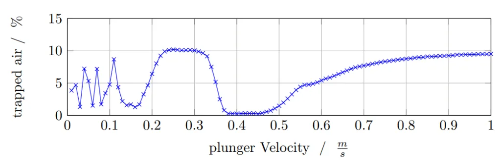
- For a 2D shot sleeve (130 mm diameter, 65% fill, 1.015 m length), a parameter study identified an optimal plunger velocity range of approximately 0.38 ms⁻¹ to 0.46 ms⁻¹ (Figure 10). This range minimizes trapped air and aligns well with experimental data from Garber [29] and Brunnhuber [2], who reported 0.46 ms⁻¹ as the critical velocity for a similar configuration.
- Different flow regimes were identified based on the plunger velocity:
- Too slow (< ~0.17 ms⁻¹): Unstable wave motion, potential for large air pockets.
- Moderately slow (~0.23 ms⁻¹ - 0.32 ms⁻¹): Piston too fast for full wave travel, leading to trapped melt.
- Optimal range (~0.38 ms⁻¹ - 0.46 ms⁻¹): Wave peak builds up to shot sleeve ceiling, pushing air out effectively.
- Too fast (> 0.46 ms⁻¹): Melt accumulates and wave plunges, entraining air.
- It was observed that operating the plunger slightly faster than the exact critical velocity is less detrimental (in terms of air entrainment) than operating it too slow, which can lead to large, isolated air pockets behind the melt front.
- The solver was successfully applied to a 3D industrial shot sleeve geometry (EA211 crank case), including its specific ingate system. Results (Figure 11, Figure 12) confirmed that increasing the plunger velocity towards the optimum in the first phase leads to a constant decrease in trapped air behind the melt front.
Figure Name List:
![Figure 7: Benchmarking of the presented OpenFOAM model with previously published data
by Korti and Aboudi [21]; the figure shows the interface positions at various time steps](https://castman.co.kr/wp-content/uploads/image-2413-1024x404.webp)
- Figure 1: Three phases of die filling.
- Figure 2: Impact of increasing plunger propagation according to [1].
- Figure 3: The two extrema of the wrong plunger speed during the first phase of the high-pressure die casting process
- Figure 4: A simplified picture of the basic mesh at t = 0
- Figure 5: A simplified picture of the mesh after an interval of Δt has elapsed and the compression strategy is used
- Figure 6: The process of layer removal during the mesh motion procedure
- Figure 7: Benchmarking of the presented OpenFOAM model with previously published data by Korti and Aboudi [21]; the figure shows the interface positions at various time steps
- Figure 8: Solving process scheme of the two phase VOF-solver
- Figure 9: The melt height at the piston boundary; analytical model according to [27] vs. result of the numerical simulation
- Figure 10: Fraction of trapped air inside the shot sleeve for slow phase velocities between 0 and 1 m/s; parameters according to table 3
- Figure 11: Trapped air for the shot-sleeve in the EA211 crank case application and the corresponding tested plunger law.
- Figure 12: The fraction occupied by air after the meltfront has propagated into the ingate.
7. Conclusion:
The research in this paper showed that it is possible even with freely available open-source software to model the computationally rather complex flow problem of shot sleeve dynamics in the slow phase without the need for costly commercial software tools. The documented results are well in line with previous CFD simulations on the matter and also analytical models derived from the shallow-water equations. Two different mesh motion strategies were presented with a preference for the layer-removal approach. The solver was also ultimately capable of solving the melt flow of 3D shot sleeves with regular industrial ingate systems attached. It was in general possible to reproduce also the results expected for 3D geometries in practical tests. The economical benefits of increasing the velocity in the slow phase of the piston motion not only for the sake of less air entrapment were also pointed out.
8. References:
- [1] B. Nogowizin, Theorie und Praxis des Druckgusses, Schiele und Schoen, Berlin, 1st edn., ISBN 978-3794907960, 2010.
- [2] E. Brunnhuber, Praxis der Druckgussfertigung, Schiele und Schoen, Berlin, ISBN 978-3794905355, 1991.
- [3] H. Kaufmann, P. Uggowitzer, Metallurgy and processing of high-integrity light metal pressure castings, Fachverlag Schiele & Schön, 2014.
- [4] J. Campbell, Complete Casting Handbook: Metal Casting Processes, Metallurgy, Techniques and Design, Elsevier Science, ISBN 9780081001202, 2015.
- [5] J. López, J. Hernández, F. Faura, G. Trapaga, Shot sleeve wave dynamics in the slow phase of die casting injection, Journal of fluids engineering 122 (2) (2000) 349-356.
- [6] F. Faura, J. López, J. Hernández, On the optimum plunger acceleration law in the slow shot phase of pressure die casting machines, International Journal of Machine Tools and Manufacture 41 (2) (2001) 173–191.
- [7] T. Tszeng, Y. Chu, A study of wave formation in shot sleeve of a die casting machine, Journal of engineering for industry 116 (2) (1994) 175–182.
- [8] C. Hirt, B. Nichols, Volume of fluid (VOF) method for the dynamics of free boundaries, J. Comp. Phys. 39 (1981) 201-225.
- [9] A. Dahle, L. Arnberg, The rheological properties of solidifying aluminum foundry alloys, JOM 48 (3) (1996) 34-37.
- [10] P. Ferrer, D. Causon, L. Qian, C. Mingham, Z. Ma, A multi-region coupling scheme for compressible and incompressible flow solvers for two-phase flow in a numerical wave tank, Computers & Fluids 125 (2016) 116–129.
- [11] R. Mayon, Z. Sabeur, M.-Y. Tan, K. Djidjeli, Free surface flow and wave impact at complex solid structures, in: 12th International Conference on Hydrodynamics, Egmond aan Zee, NL, 18-23 September, 10pp., 2016.
- [12] S. Kohlstädt, M. Vynnycky, A. Neubauer, A. Gebauer-Teichmann, Comparative RANS turbulence modelling of lost salt core viability in high pressure die casting, accepted for publication in Prog. Comp. Fluid Dyn., 2018.
- [13] J. Brackbill, D. Kothe, C. Zemach, A continuum method for modeling surface tension 100 (2) (1992) 335-354.
- [14] H. Rusche, Computational fluid dynamics of dispersed two-phase flows at high phase fractions, Ph.D. thesis, Imperial College London (University of London), 2003.
- [15] H. Versteeg, W. Malalasekera, An Introduction to Computational Fluid Dynamics: The Finite Volume Method, Pearson Education Limited, 2007.
- [16] F. Menter, 2-equation eddy-viscosity turbulence models for engineering applications, AIAA J. 32 (1994) 1598–1605.
- [17] E. Robertson, V. Choudhury, S. Bhushan, D. Walters, Validation of OpenFOAM numerical methods and turbulence models for incompressible bluff body flows, Computers & Fluids 123 (2015) 122-145.
- [18] F. Menter, M. Kuntz, R. Langtry, Ten years of industrial experience with the SST turbulence model, Turbulence, Heat and Mass Transfer 4 (1) (2003) 625-632.
- [19] M. Koch, C. Lechner, F. Reuter, K. Köhler, R. Mettin, W. Lauterborn, Numerical modeling of laser generated cavitation bubbles with the finite volume and volume of fluid method, using OpenFOAM, Computers & Fluids 126 (2016) 71-90.
- [20] F. White, Fluid mechanics, in SI units, McGraw-Hill, 2011.
- [21] A. Korti, S. Abboudi, Numerical simulation of the interface molten metal air in the shot sleeve chambre and mold cavity of a die casting machine, Heat and Mass Transfer 47 (11) (2011) 1465-1478.
- [22] H. Jasak, A. Jemcov, Z. Tukovic, OpenFOAM: A C++ Library for Complex Physics Simulations, in: International Workshop on Coupled Methods in Numerical Dynamics IUC, 2007.
- [23] H. Weller, G. Tabor, H. Jasak, C. Fureby, A tensorial approach to computational continuum mechanics using object orientated techniques, Computers in Physics 12(6) (1998) 620-631.
- [24] H. Jasak, OpenFOAM: open source CFD in research and industry, International Journal of Naval Architecture and Ocean Engineering 1 (2) (2009) 89-94.
- [25] S. Patankar, D. Spalding, A calculation procedure for heat, mass and momentum transfer in three-dimensional parabolic flows, in: Numerical Prediction of Flow, Heat Transfer, Turbulence and Combustion, Elsevier, 54-73, 1983.
- [26] R. Issa, Solution of the implicitly discretised fluid flow equations by operator-splitting, Journal of Computational Physics 62 (1) (1986) 40–65.
- [27] A. Reikher, M. Barkhudarov, Casting: an analytical approach, Springer Science & Business Media, 2007.
- [28] M. Castro, M. Semplice, Third-and fourth-order well-balanced schemes for the shallow water equations based on the CWENO reconstruction, International Journal for Numerical Methods in Fluids 89 (8) (2019) 304-325.
- [29] L. Garber, Theoretical analysis and experimental observation of air entrapment during cold chamber filling, Die Casting Engineer 26 (3) (1982) 14-15.
9. Copyright:
- This material is a paper by "S. Kohlstädt, M. Vynnycky, S. Goeke, A. Gebauer-Teichmann". Based on "On determining the critical velocity in the high-pressure die casting machine's shot sleeve using CFD".
- Source of the paper: [DOI URL placeholder - to be added if/when available, as this is a preprint from April 25, 2019, submitted to Elsevier]
This material is summarized based on the above paper, and unauthorized use for commercial purposes is prohibited.
Copyright © 2025 CASTMAN. All rights reserved.
Key Questions & Answers for Researchers
Q1. What is the main objective of determining the critical velocity in the HPDC shot sleeve's slow phase?
A1. The main objective is to minimize air entrapment within the molten metal by ensuring that the air inside the shot sleeve is effectively pushed out ahead of the melt front, thereby improving the quality of the final casting (as discussed in the context of Figure 3 and Figure 10).
Q2. Which CFD modeling approach was employed for the melt-air system in the shot sleeve?
A2. The study used an Eulerian volume-of-fluid (VOF) approach to model the melt-air system. Air was treated as a compressible perfect gas, and turbulence was handled using a RANS approach with the Menter SST k-ω model (Abstract, Section 2).
Q3. How was the CFD solver developed in this study validated?
A3. The solver was validated by comparing its simulation results against analytical models, such as the one by Reikher and Barkhudarov [27] for melt height (Figure 9), and against previously published CFD data from Korti and Aboudi [21] for interface positions (Figure 7).
Q4. For the specific 2D shot sleeve case studied (130mm diameter, 65% fill, 1.015m length), what was the identified optimal plunger velocity range?
A4. The optimal plunger velocity range was found to be approximately 0.38 ms⁻¹ to 0.46 ms⁻¹. This range resulted in minimal trapped air and is consistent with experimental data from Garber [29] and Brunnhuber [2] (Section 5.1, Figure 10).
Q5. What are the consequences if the plunger velocity deviates significantly from the optimal critical velocity?
A5. If the plunger moves too slow, the wave can separate from the plunger and propagate freely, potentially trapping a large air pocket behind the melt front. If the plunger moves too fast, the melt accumulates rapidly, causing the wave to crash and entrain air into the melt (Figure 3, Section 5.1).
Q6. Were the findings from 2D simulations applicable to more complex 3D industrial geometries?
A6. Yes, the study demonstrated that the solver and the understanding of critical velocity could be applied to a real-world 3D shot sleeve (EA211 crank case) including its industrial ingate system. The 3D simulations confirmed that operating near the optimal velocity reduces trapped air (Section 5.2, Figure 11, Figure 12).