Myeong Jin Koa, Sung-Ho Leea, Soon Sub Parka*
ABSTRACT
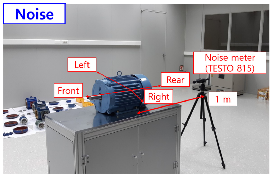
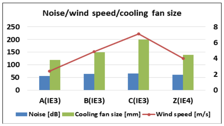
In this study, a 2.2 kW super-premium (IE4) class 4-pole three-phase induction motor was designed and developed. We compared this prototype motor with the industrial induction motors sold by leading international companies. We designed and fabricated a stator, an Al rotor, housing, bearing front and rear covers made of Al 6061, a shaft, and a cooling fan. The cooling fan produced with 3D printing technology was assembled on the unload shaft. Following motor assembly, its mechanical performance, such as noise, vibration, wind speed, and efficiency, was analyzed. Compared with the considered international-standard motors, our proposed motor showed superior performance in terms of noise, vibration, and efficiency but not in terms of air gap and wind speed.
본 연구에서는 2.2kW급 슈퍼프리미엄(IE4)급 4극 3상 유도전동기를 설계 및 개발하였다. 우리는 이 프로토타입 모터를 주요 국제 기업에서 판매되는 산업용 유도 모터와 비교했습니다. Al 6061로 제작된 고정자, Al 회전자, 하우징, 베어링 전면 및 후면 커버, 샤프트 및 냉각 팬을 설계 및 제작했습니다. 3D 프린팅 기술로 제작된 냉각 팬을 언로드 샤프트에 조립했습니다. 모터 조립 후 소음, 진동, 풍속, 효율 등의 기계적 성능을 분석하였다. 우리가 제안한 모터는 국제표준으로 고려되는 모터와 비교하여 소음, 진동, 효율 면에서 우수한 성능을 보였으나 공극과 풍속에서는 그렇지 않았다.
Introduction
For conserving energy and reducing greenhouse gas emissions, policies on minimum energy performance standards (MEPS) have been implemented, and the distribution of high-efficiency motors have been promoted worldwide. In accordance with the global trend of enhancing the minimum efficiency standard from IE2 to IE3, the standard was enhanced to IE3 in South Korea as well in 2015, and it is expected that the motor-efficiency standard will be enhanced to IE4 and IE5 by 2030.
With the continuous development of motor control technology and power semiconductor devices, the utilization ranges of various motors, including induction motors, are continuously expanding. With the increase in industrial rotary-machine size, technologies to reduce the driving motor noise are being continuously developed.
Compared to advanced overseas companies that dominate the motor market, the research and development infrastructure and personnel available in South Korea are not competitive. Moreover, latecomers, such as China, are rapidly catching-up; therefore, the development of this technology is urgently required domestically.
Motor losses can be reduced, and motor efficiency can be improved by replacing the existing die-cast aluminum (Al) rotors with die-cast copper (Cu) rotors. In induction motors with die-cast Cu rotors, the temperature increase can be reduced by 2-5℃ compared to those with die-cast Al rotors because of the reduced rotor heating caused by low copper loss in the rotors[1-3]. Currently, Al die casting is mainly used because Cu die casting is difficult due to the high melting temperature of Cu.
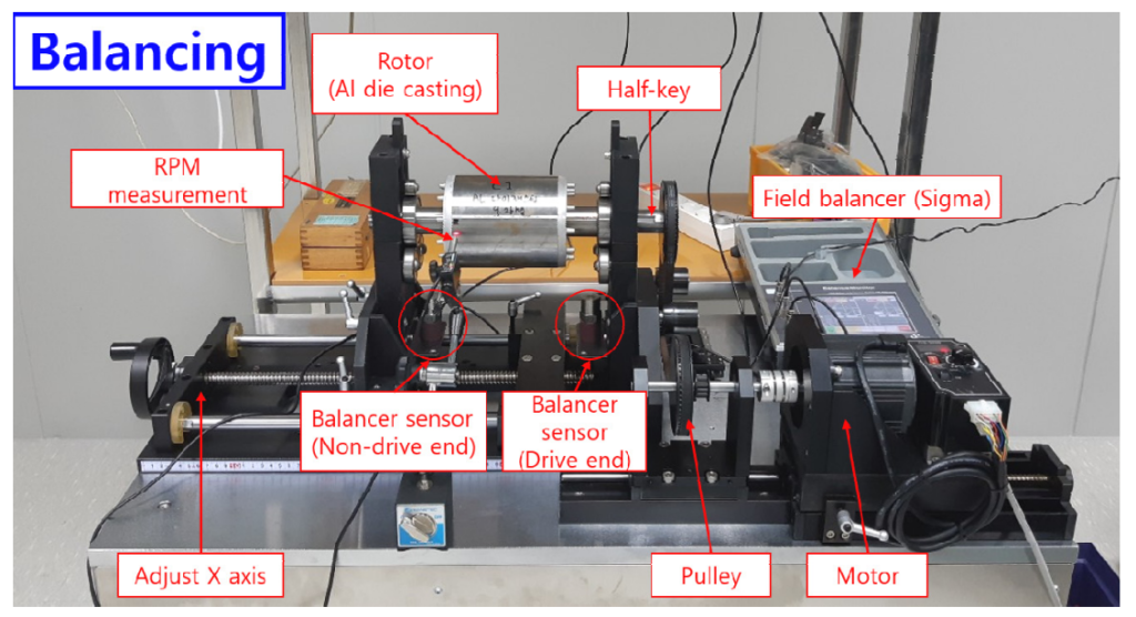
Although Al rotors are used for IE3-class induction motors, the use of rotor materials with high electrical conductivity is required to achieve IE4-class efficiency levels. Therefore, it is necessary to design and develop hybrid rotors that combine the advantages of Al rotors, and the low copper loss of Cu rotors during initial motor operation and the high efficiency during operation under rated load. In this study, the products of advanced companies leading the domestic and overseas induction motor markets are compared with a prototype induction motor designed and developed in this study to construct a database for the noise, vibration, balancing, and air gap.
In addition, the key components of the developed 2.2-kW IE4 (super premium)-class 4-pole 3-phase induction motor, such as the stator, shafting, Al alloy housing, bearing front and rear covers, three-dimensional (3D) printing cooling fan, and die-cast Al/Cu rotors, are assembled to evaluate the mechanical performance of the motor.
A precision machined shaft with shaft oscillations less than 10 µm is shrink-fitted with the bearings and Al/Cu rotors; the balancing at the drive end (DE) and nondrive end (NDE) of the shaft are less than 0.4 g. A cooling fan fabricated with 3D printing technology is assembled at the NDE to complete the shafting. A stator with a 43.7% space factor and 0.68 Ω (@ 25℃) resistance that meets the (0.80 × 2 + 0.85 × 2) × 28 turn winding specification is developed and shrink-fitted with the housing.
The mechanical and electrical performances of the assembled motor, such as the noise, vibration, wind speed, temperature increase, power factor, and efficiency, are analyzed. The rest of this paper is organized as follows. Section 2 analyzes the mechanical performance of commercial induction motors developed by leading international companies.
Section 3 focuses on the design, development, and evaluation of the proposed 2.2-kW induction motor.
Finally, Section 4 summarizes the results of the study.


References
[1] Lie, S., Pietro, D., 1995, Copper Die-cast Rotor Efficiency
Improvement and Economic Consideration, IEEE Trans. Energy
Convers., 10:3 419-424, https://doi.org/10.1109/60.464863.
[2] Peters, D. T., Cowie, J. G., Brush, E. F., Midson, S. P., 2002, Use
of High Temperature Die Material and Hot Dies for High
Pressure Die Casting Pure Copper and Copper Alloys,
Transactions of the North American Die Casting Association
Congress.
[3] Malinowski, J., McCormick, J., Dunn, K., 2004, Advanced
in Construction Techniques of AC Induction Motors:
Preparation for Super-premium Efficiency Levels, IEEE
Trans. Ind. Appl., 40:6 1665-1670, https://doi.org/10.1109/
TIA.2004.836300.
[4] IEC, 2002, Rotating Electrical Machines-Part9: Noise Limits,
IEC 60034-9:2002, International Electrotechnical Commission,
Geneva.
[5] Jun, O. S., Kim, J. O., 1999, Free Bending Vibration of a
Multi-step Rotor, J. Sound Vibr., 224:4 625-642, https://doi.org/
10.1006/jsvi.1999.2206.
[6] Kim, P. Y., 1987, A New Method for the Critical Speed
Calculation of Rotor-bearing Systems, Doctoral Dissertation,
University of Ottawa, Canada.
[7] Darlow, M. S., 1987, A Method for Torsional Critical Speed
Calculation of Practical Industrial Rotors, Proc. for the
International Conference on Vibration Engineering, 759-764.
[8] IEC, 1991, Dimensions and Output Series for Rotating Electrical
Machines — Part 1: Frame Numbers 56 to 400 and Flange
Numbers 55 to 1080, IEC 60072-1, International Electrotechnical
Commission, Geneva.
[9] Darlow, M. S., 1987, Balancing of High-Speed Machinery:
Theory, Methods and Experimental Results, Mech. Syst. Signal
Proc., 1:1 105-134, https://doi.org/10.1016/0888-3270(87)900
87-2.
[10] ISO, 1986, Mechanical Vibration—Balance Quality Requirements
of Rigid Rotors—Part 1: Determination of Permissible
Residual Unbalance, ISO 1940-1, International Organization
for Standardization, Geneva.
[11] ISO, 1998, Mechanical Vibration—Methods and Criteria for
the MechanicalBalancing of Flexible Rotors, ISO 11342,
International Organization for Standardization, Geneva.
[12] Lee, C.-W., 1993, Vibration Analysis of Rotors, Kluwer
Academic Publishers, The Netherlands.
[13] Beyer, W. H., 1979, CRC Standard Mathematical Tables, CRC
Press, Boca Raton, FL, USA.
[14] ISO, 1990, Vibration and Shock—Experimental Determination
of Mechanical Mobility—Part 2: Measurements Using
Single-point Translational Excitation with an Attached
Vibration Exciter, ISO 7626-2, International Organization for
Standardization, Geneva.