Can Additive Manufacturing Create Lightweight HPDC Dies That Withstand Extreme Stresses? A Simulation Study
This technical summary is based on the academic paper "HPDC Die design for Additive Manufacturing" by Mohammadali Baradaran and Ambareeksh Tharayil Pradeep, published by Jönköping University (2018).
Keywords
- Primary Keyword: Additive Manufacturing in HPDC
- Secondary Keywords: Lightweight Die Design, Thermal Stress Simulation, Conformal Cooling, HPDC Die Life, MAGMA Simulation, ABAQUS Simulation
Executive Summary
- The Challenge: Conventional High Pressure Die Casting (HPDC) dies are heavy and have long manufacturing lead times; lightweight dies made with Additive Manufacturing (AM) are a potential solution, but their structural durability under casting loads is a major unknown.
- The Method: The study used a coupled simulation approach to compare the thermal and mechanical stresses on a conventional solid HPDC die insert versus a lightweight, honeycomb-structured insert designed for AM.
- The Key Breakthrough: The lightweight honeycomb design demonstrated significantly improved cooling rates and a shorter cycle time but ultimately failed under the simulated thermal and mechanical loads due to its thin-walled features.
- The Bottom Line: While the specific lightweight design failed, the research validates the potential for faster cycle times with AM designs, highlighting the critical need for advanced topology optimization to balance mass reduction with structural integrity.
The Challenge: Why This Research Matters for HPDC Professionals
In the world of High Pressure Die Casting, efficiency and tool life are paramount. Conventional manufacturing of HPDC dies is a subtractive process involving extensive machining, which leads to long lead times and significant design constraints. The promise of Additive Manufacturing (AM), or 3D printing, is to overcome these hurdles. AM offers unparalleled design freedom, enabling complex features like conformal cooling channels that follow the part's contour for more uniform and efficient cooling. This can lead to shorter cycle times and higher-quality parts.
However, a major barrier to adopting AM for HPDC tooling is cost and performance. AM is inherently slower and more expensive per unit of material than conventional methods. To be economically viable, an AM-produced die must be as light as possible (mass-efficient) to reduce print time and material cost. This leads to a critical question that this research addresses: Can a lightweight HPDC die, designed with thin-walled features like a honeycomb structure, actually withstand the intense thermal and mechanical loads of the casting cycle? This study was designed to find the answer.
The Approach: Unpacking the Methodology
To investigate the viability of a lightweight AM die, the researchers conducted a rigorous comparative simulation, analyzing a conventional design against a novel lightweight design through a multi-stage process.
Method 1: Dual CAD Design
Two distinct designs for the HPDC die inserts (core and cavity) were modeled in SolidWorks.
- Initial Design: A conventional, solid block of tool steel, representing the standard industry approach.
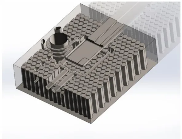
- Final Design: A lightweight version designed for Additive Manufacturing. This design replaced solid mass with an internal honeycomb lattice structure and incorporated conformal cooling channels, significantly reducing its overall weight.
Method 2: Thermal Simulation with MAGMASoft
Both die designs were subjected to a simulated HPDC cycle using MAGMASoft, a specialized casting simulation software. This step was crucial for generating a detailed temperature history for every point within the die inserts, from the initial injection of molten metal to the final ejection of the solidified part.
Method 3: Stress Analysis with ABAQUS
The temperature data from MAGMA was mapped onto a high-fidelity Finite Element Method (FEM) mesh created in HyperMesh. This model was then imported into ABAQUS to perform a fully coupled thermal-displacement analysis. This final step calculated the resulting von Mises stresses throughout the die inserts, revealing whether they would deform or fail under the combined thermal and mechanical loads of the HPDC process.
The Breakthrough: Key Findings & Data
The comparative simulation yielded two critical and seemingly contradictory findings, painting a clear picture of both the promise and the peril of lightweight AM die design.
Finding 1: Lightweight Design Offers Superior Cooling and Faster Cycle Times
The simulation confirmed a key benefit of AM-enabled designs. The honeycomb structure and conformal cooling channels in the lightweight "Final Design" allowed for much more effective heat dissipation. As shown in the cooling curves (Figure 4.25 and 4.28), this superior thermal performance resulted in a reduction of the total cycle time by approximately two seconds compared to the conventional "Initial Design." In high-volume production, such a reduction represents a significant increase in productivity.
Finding 2: The Lightweight Design Failed Under Simulated Loads
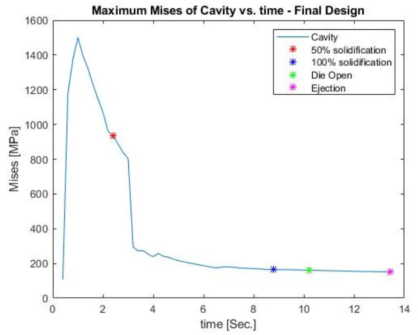
Despite its thermal advantages, the lightweight die failed the structural test. The analysis showed that the stresses generated within the "Final Design" far exceeded the material's yield strength of 1480 MPa.
- As seen in Figure 4.34, the peak von Mises stress in the lightweight cavity reached 2745 MPa, and the core reached 1501 MPa, indicating catastrophic failure.
- In stark contrast, the conventional "Initial Design" performed reliably, with a maximum stress of 1125 MPa (Figure 4.31), well within the safe operating limits of the material. The thin walls of the honeycomb structure were simply not robust enough to handle the immense pressures and thermal expansion forces.
Practical Implications for R&D and Operations
- For Process Engineers: This study suggests that adjusting die design using AM principles, particularly with conformal cooling, may contribute to a significant reduction in cycle time (a 2-second improvement was noted), directly boosting production throughput.
- For Quality Control Teams: The data in Figure 4.34 of the paper illustrates the extreme stress concentrations that can occur in thin-walled AM structures. This highlights the need for new inspection criteria and NDT methods focused on verifying the integrity of these complex, lightweight features before they enter production.
- For Design Engineers: The findings indicate that while a honeycomb structure improves cooling, its thin walls are a critical point of failure. A simple substitution of solid mass with a generic lattice is insufficient. This proves that iterative topology optimization is essential in the early design phase to create a structure that is both lightweight and strong enough for the demanding HPDC environment.
Paper Details
HPDC Die design for Additive Manufacturing
1. Overview:
- Title: HPDC Die design for Additive Manufacturing: Simulation and Comparison of Thermal Stresses in HPDC die designed for Additive Manufacture
- Author: Mohammadali Baradaran and Ambareeksh Tharayil Pradeep
- Year of publication: 2018
- Journal/academic society of publication: Jönköping University, School of Engineering
- Keywords: HPDC, Additive manufacturing, MAGMA simulation, Structural analysis, Casting Dies, ABAQUS simulation, Expansion, Die Life, HTC, Cooling Curves
2. Abstract:
Additive manufacturing has a great potential to benefit die manufacture by shortening the lead time considerably and lifting the limitations on design complexity imposed by conventional manufacturing techniques. However, AM has its own requirements that together are known as Design for Additive Manufacturing and account for the process limitations. One of the significant requirements is mass efficiency of the design (it should be as light as possible). If it’s not fulfilled, AM won’t be able to make an economical solution or substitution despite having outstanding benefits. The present investigation has been framed with respect to such concern.
This investigation attempts to draw a comparison between the performance of two design variants. Additionally, it has been tried to study the employed method, document implementation of the approach, and identify the challenges in accordance with design for additive manufacturing.
Simulation of thermal stresses generated in die inserts for a given component during one cycle of high pressure die casting is presented. Initial design of the die inserts is subjected to redesign with the intention of mass reduction by incorporating honeycomb structure. Temperature evolution and resultant thermal stresses are analyzed for redesign and compared to those of original design.
Simulation of high pressure die casting was carried out in MagmaSoft to obtain temperature history of die inserts and cast. Implicit nonlinear elastic fully coupled thermal displacement model was setup in Abaquus in which Magma results were used as input for stress calculation.
Results show that according to our specific design, HPDC die with thin walled feature cannot withstand the thermal and mechanical load. However, with iterative analysis and proper topology optimization, a lightweight complex geometry die can be successfully made.
3. Introduction:
Additive Manufacturing (AM) presents a paradigm shift from conventional subtractive manufacturing by building parts layer-by-layer, offering significant design freedom. While AM has seen advancements, it has not yet replaced high-volume processes like HPDC due to high initial costs, expensive materials, and slow processing times. However, AM is gaining traction as a supplemental technique, particularly for creating complex tooling. One of its key advantages in mold manufacturing is the ability to incorporate conformal cooling channels, which follow a component's contour for efficient, uniform cooling, leading to improved part quality and reduced cycle times.
Despite these benefits, the adoption of AM for tooling is hindered by a lack of established design guidelines. To be economically viable, AM parts must be mass-efficient (lightweight), which is often achieved using lattice or honeycomb structures. This work addresses the central challenge of whether such a lightweight HPDC die insert can withstand the severe thermal and mechanical loads inherent in the casting process. The research question is formulated as: "Can a lightweight HPDC die with thin/walled features withstand the thermal and mechanical loads that act on it during the casting cycle?" The study aims to develop a design that minimizes mass while ensuring no plastic deformation occurs during operation.
4. Summary of the study:
Background of the research topic:
The study is situated within the field of High Pressure Die Casting (HPDC), a process where molten metal is injected at high velocity and pressure into reusable steel dies. The performance and lifespan of these dies are critical for production efficiency and part quality. Dies are subjected to intense thermal stresses from the molten metal and mechanical stresses from the machine's locking force. Conventionally, dies are solid, heavy, and produced through time-consuming machining. Additive Manufacturing (AM), specifically Selective Laser Melting (SLM), offers an alternative for producing die components with complex internal geometries, such as conformal cooling channels and lightweight lattice structures, which are impossible to create with traditional methods.
Status of previous research:
The paper acknowledges that while AM for tooling is an active area of research, particularly for injection molding, its application in higher-temperature metal casting processes like HPDC is less developed. Existing research has demonstrated AM's ability to create tools with conformal cooling, reducing cycle times. However, there is a recognized gap in established design methodologies and guidelines for creating structurally sound, lightweight AM components for high-stress applications. The challenge lies in balancing the economic need for mass reduction with the mechanical requirement of withstanding cyclic thermal and mechanical loads. The frontier of research involves developing printable alloys, optimizing AM process parameters, and integrating topology optimization with AM design to ensure tool integrity.
Purpose of the study:
The primary purpose of this investigation is to determine if a lightweight HPDC die insert, designed for Additive Manufacturing with thin-walled features, can successfully withstand the thermal and mechanical stresses of a single casting cycle. The study compares the performance of a novel lightweight design featuring a honeycomb structure against a traditional, solid die insert design. It aims to analyze the temperature evolution and resultant thermal stresses in both variants to evaluate the feasibility of the lightweight approach.
Core study:
The core of the study involves a multi-software simulation workflow. Two die insert designs were developed: an "Initial Design" representing a conventional solid die, and a "Final Design" representing a lightweight, honeycomb-structured die for AM. The HPDC process was first simulated in MAGMASoft to obtain the temperature history of the die inserts over one full cycle. This thermal data was then used as an input for a structural analysis in ABAQUS. A Finite Element Method (FEM) model was created in HyperMesh, and the temperature fields were mapped onto this model. A fully coupled thermal-displacement analysis was then performed in ABAQUS to calculate the von Mises stresses generated in both the initial and final designs, allowing for a direct comparison of their structural performance under simulated operational loads.
5. Research Methodology
Research Design:
The study employed a comparative simulation-based research design. Two distinct design variants of an HPDC die insert were created and analyzed:
1. Initial Design: A conventional, solid geometry.
2. Final Design: A lightweight geometry incorporating a honeycomb internal structure and conformal cooling channels, optimized for additive manufacturing.
The research followed a sequential workflow, linking specialized software for each analysis stage to create a comprehensive thermal-structural simulation.
Data Collection and Analysis Methods:
The methodology did not involve physical data collection but rather data generation through simulation.
- CAD Modeling: Die insert geometries were created in SolidWorks.
- Thermal Analysis: The HPDC process was simulated using the Finite Difference Method (FDM) in MAGMASoft to generate nodal temperature history data for a complete casting cycle.
- Meshing: 3D tetrahedral FEM meshes of the die inserts were created in HyperMesh.
- Stress Analysis: The MAGMASoft temperature data was mapped onto the FEM mesh. A static nonlinear implicit fully coupled thermal-displacement analysis was conducted in ABAQUS to calculate the evolution of thermal stresses (von Mises stress) throughout the cycle.
- Data Processing: MATLAB scripts were used to process and format the temperature data files for compatibility between MAGMA and ABAQUS and to extract and plot the final results.
Research Topics and Scope:
The research topic is the design and analysis of HPDC dies for Additive Manufacturing, with a focus on evaluating the structural integrity of lightweight designs. The scope of the study is limited to the simulation of a single casting cycle. It does not account for long-term failure mechanisms such as thermal fatigue, which would occur over thousands of cycles. The analysis concentrates on the thermal and mechanical stresses within the die inserts themselves; aspects like melt flow dynamics and casting porosity formation were not the primary focus.
6. Key Results:
Key Results:
- The lightweight "Final Design" with a honeycomb structure demonstrated superior cooling performance, reducing the overall casting cycle time by approximately 2 seconds compared to the conventional "Initial Design."
- The simulation of the conventional "Initial Design" showed a maximum von Mises stress of approximately 1125 MPa in the core, which is well below the material's yield point of 1480 MPa, indicating it would withstand the process loads.
- The simulation of the lightweight "Final Design" resulted in stresses that far exceeded the material's yield strength. The peak von Mises stress was 2745 MPa in the cavity and 1501 MPa in the core, indicating that this specific thin-walled design would fail under operational conditions.
- The high stresses in the final design dissipated more quickly than in the initial design due to its more effective cooling.
Figure Name List:
- Figure 1.1: Layout of Steps
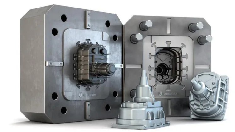
- Figure 2.1: Die Slabs containing Die insert
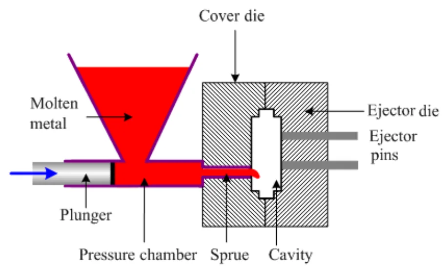
- Figure 2.2 Hot Chamber HPDC setup
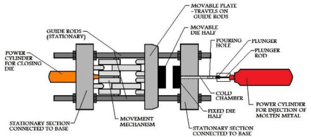
- Figure 2.3 Cold Chamber HPDC Setup
- Figure 2.4: Variation of IHTC value with time and temperature
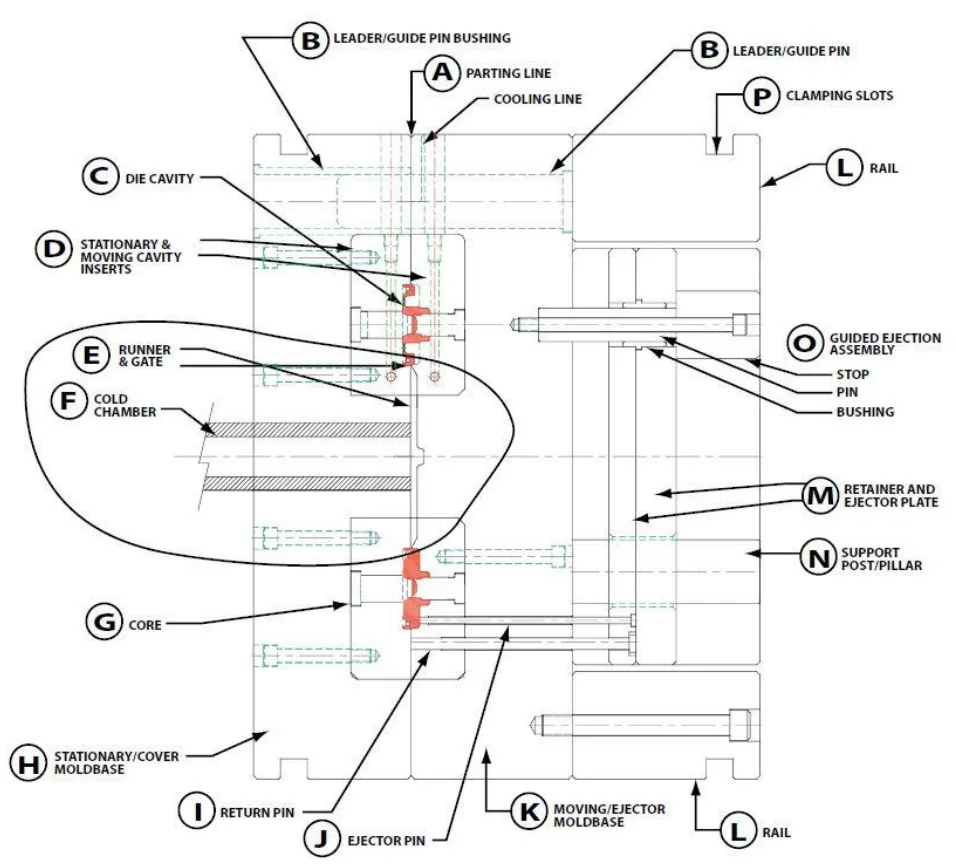
- Figure 2.5: HPDC die components
- Figure 2.6- Procedure of Die design
- Figure 2.7: Selective laser Melting
- Figure 2.8: Build orientation in 3Dprinting
- Figure 3.1 : Flow of the work
- Figure 3.2 : Component - Top view.
- Figure 3.3 : Component - Bottom view.
- Figure 3.4 : Component - Isometric view, left angle.
- Figure 3.5 : Component - Isometric view, right angle.
- Figure 3.6 : Component - Sectioned view, right angle.
- Figure 3.7 : Component - Sectioned view - left angle.
- Figure 3.8 : Core (Ejector die) – Top view.
- Figure 3.9 : Core (Ejector die) – Isometric view.
- Figure 3.10 : Cavity (Cover die) – Top view.
- Figure 3.11 : Cavity (Cover die) – Isometric view.
- Figure 3.12 : Bottom view of new core with honecomb structure.
- Figure 3.13 : Transparent top view of core with honeycomb structure showing the relative position of cooling channels.
- Figure 3.14 : Left view of core with honeycomb structure showing depth of the honeycom cells.
- Figure 3.15 : Isometric view of core with honeycomb structure showing depth of the cells around coolling channles. Transparent regions are solid structure.
- Figure 3.16 : Top isometric view of cavity with honeycomb structure.
- Figure 3.17 : Bottom view of cavity with honeycomb structure.
- Figure 3.18 : Transparent top view of cavity with honeycomb structure showing the position of cooling channels around the cavity and around the inlet.
- Figure 3.19 : Transparent top isometric view of cavity with honeycomb structure showing depth of the honeycomb cells around cooling channels. Transparent regions are solid structure.
- Figure 3.20 : Transparent left view of cavity with honeycomb structure showing depth of the honeycomb cells. Transparent regins are solid structure.
- Figure 3.21 : Closer transparent view of cavity with honeycomb structure.
- Figure 3.22 : Assembly of cating materials inside Magma geometry panel. From left to right: biscuite and inlet, runner, cast (component), overflow channel.
- Figure 3.23 : Side view of casting materials assembly in Magma and their relative positions.
- Figure 3.24 : Final Assembly in Magam. Top half represents cavity (cover die) containing inlet, biscuite, cast and one set of cooling channels. Bottom half represents core (ejector die) containing runner, overflow channel, ejector pins and one set of cooling channel.
- Figure 3.25 : Geometry tree.
- Figure 3.26 : Mesh of the ejector die.
- Figure 3.27 : Mesh of casting materials and ejector die.
- Figure 3.28 : Mesh of the casting materials.
- Figure 3.29 : Material definition window and defined settings.
- Figure 3.30 : Heat transfer definition window.
- Figure 3.31 : Process timeline for a HPDC cycle.
- Figure 3.32 : Events and sub-events of a casting cycle.
- Figure 3.33 : Active shot chamber length.
- Figure 3.34 : positio of plunger in shot sleeve when port is covered.
- Figure 3.35 : Shot curve definition panel.
- Figure 3.36 : Filling shot curve.
- Figure 3.37 : Intensification difinition window.
- Figure 3.38 : Die open definition window.
- Figure 3.39 : Dir tempering control window.
- Figure 3.40 : Results order condistion window.
- Figure 3.41: Top view from assembly of component, air pockets, and cooling channels in core.
- Figure 3.42 : Isometric view from assembly of component, air pockets, and cooling channels in core.
- Figure 3.43 : Assembly of air pockets and cooling channels in cavity.
- Figure 3.44 : Position of inserts in surrounding walls – Final design.
- Figure 3.45 : Mesh for the new cavity - Top.
- Figure 3.46 : Mesh for the new cavity – Bottom.
- Figure 3.47 : Mesh for the new core – Bottom.
- Figure 3.48 : Material definition window – Final design.
- Figure 3.49 : Heat transfer definition window for final design.
- Figure 3.50 : Size and bias panel of 2D auto meshing.
- Figure 3.51: Small features on core that need finer mesh than sorrounding areas.
- Figure 3.52 : Small feature shown in Figure 3.51 from different angle.
- Figure 3.53 : Surface deviation panle of 2D automeshing.
- Figure 3.54 : Mesh transition on core.
- Figure 3.55 : Check element tab where element quality check can be carried out for 2D and 3D mesh.
- Figure 3.56 : Edge panel where operation for finding free edges and T-connections is carried out.
- Figure 3.57 : Tetramesh control panel of tetramesh in 3D meshing.
- Figure 3.58 : tetramesh control panel for executing 3D mesh creation. 2D mesh is selected as input for Fixedtrias/quads to tetramesh.
- Figure 3.59 : Meshed cavity, final design, top view.
- Figure 3.60 : Meshed cavity, final design, side view.
- Figure 3.61 : Meshed cavity, final design, bottom view.
- Figure 3.62 : a sectioned view showing the solid elements, cavity, final design.
- Figure 3.63 : Side sectioned view showing solid elements, cavity, final design.
- Figure 3.64 : Meshed core, top view, final design.
- Figure 3.65 : Meshed core, showing mesh transition, final design.
- Figure 3.66 : Meshed core, bottom view, new design.
- Figure 3.67 : Meshe core, bottom view, closer look, final design.
- Figure 3.68 : Sectined view of core showing solid element, final deesign.
- Figure 3.69 : Sectined view of core showing solid element, final deesign.
- Figure 3.70 : Meshed cavity, top view, initial design.
- Figure 3.71 : Meshed cavity, isometric top view, initial design.
- Figure 3.72 : Meshed cavity, bottom view, initial design.
- Figure 3.73 : Sectioned view of cavity shoeing solid elements, initial design.
- Figure 3.74 : Meshed core, top view initial design.
- Figure 3.75 : Meshed core, isometri top view, initial design.
- Figure 3.76 Sectined view of core showing solid elements, initrial design.
- Figure 3.77 : Solver deck export panel for mesh export in HyperMesh.
- Figure 3.78 : Entity State panel where components of interest can be selected for mesh export.
- Figure 3.79 : Model tree view in Abaqus.
- Figure 3.80 : Part copy window where joint parts in assembly can be detached.
- Figure 3.81 : Assembly in Abaqus.
- Figure 3.82 : Basic tab of step definition window in Abaqus.
- Figure 3.83 : Increment tab of step definition in Abaqus.
- Figure 3.84 : Die movment constrained along X axis.
- Figure 3.85 : Die Movement constrained alonf Y axix.
- Figure 3.86 : Bottom surface of the cavity is pinned. Movement of die inserts along Z axis is restricted.
- Figure 3.87 : Defining a uniform load applied on the top of the core.
- Figure 3.88 : Defining the contact surface in interaction module.
- Figure 3.89 : Definition of tangential behaviour in interaction properties.
- Figure 3.90 : Definition of normal behaviour in interaction properties.
- Figure 3.91: Assigning initial temperature of the inserts in predefined field.
- Figure 3.92 : Export file window in Magma.
- Figure 3.93 : Material selection window in Magma.
- Figure 3.94 : Results category selection for export in Magma.
- Figure 3.95 : An example of temperature file generated by result export in Magma (Left). Same temperature file after being modified by MATLAB.
- Figure 4.1 : Temperature profile of core at the end of filling (0.38 s, Max Temp = 178 ºC).
- Figure 4.2 : Temperature profile of core at 50% solidification (t = 2.2 s, Max T= 359 ºC).
- Figure 4.3 : Temperature profile of core at 100% solidification (t = 8.91 s, Max T= 348 ºC).
- Figure 4.4 : Temperature profile of core at die open (t = 10.12 s, Max T= 327 ºC).
- Figure 4.5 : Temperature profile of core at ejection (t = 15.14 s, Max T= 223 ºC).
- Figure 4.6 Temperature profile of cavity at the end of filling (t = 0.38 s, Max T= 170 ºC).
- Figure 4.7 Temperature profile of cavity at 50% solidification (t = 2.2 s, Max T= 367 ºC).
- Figure 4.8 Temperature profile of cavity at 100% solidification (t = 8.91 s, Max T= 310 ºC).
- Figure 4.9 Temperature profile of cavity at die open (t = 10.12 s, Max T= 298 ºC).
- Figure 4.10 Temperature profile of cavity at ejection (t = 15.14 s, Max T= 215 ºC).
- Figure 4.11 Temperature profile of core at 50% solidification (t = 1.80 s, Max T= 361 ºC).
- Figure 4.12 Temperature profile of core at 100% solidification (t = 7.35 s, Max T= 367 ºC).
- Figure 4.13 Temperature profile of core at die open (t = 8.44 s, Max T= 348 ºC).
- Figure 4.14 Temperature profile of core at ejection (t = 13.45 s, Max T= 251 ºC).
- Figure 4.15 Temperature profile of core at 50% solidification (t = 1.80 s, Max T= 385 ºC).
- Figure 4.16 Temperature profile of core at 100% solidification (t = 7.35 s, Max T= 322 ºC).
- Figure 4.17 Temperature profile of core at die open (t = 8.44 s, Max T= 306 ºC).
- Figure 4.18 Temperature profile of cavity at ejection (t = 13.45 s, Max T= 194 ºC).
- Figure 4.19 : Cooling behavior of cavity- initial design.
- Figure 4.20 : Cooling behavior of core- initial design.
- Figure 4.21 : Superimposed cooling behaviors of cavity and core - initial design.
- Figure 4.22 : Cooling behavior of cavity- final design.
- Figure 4.23 : Cooling behavior of core- final design.
- Figure 4.24 : Superimposed cooling behaviors of cavity and core – final design.
- Figure 4.25 : Superimposed cooling behaviors of cavity and core – initial and final design (new design).
- Figure 4.26 : Cooling behavior of cast in initial design.
- Figure 4.27 : Cooling behaviour of cast in final design (new design).
- Figure 4.28 : Superimposed cooling behaviors of cast in initial and final design (new design).
- Figure 4.29 : Unaveraged maximum mises stress Vs. time for cavity initial design.
- Figure 4.30 : Unaveraged maximum mises stress Vs. time for core initial design.
- Figure 4.31 : Superimposed unaveraged maximum mises stresses of core and cavity – Initial design.
7. Conclusion:
The study concludes that the specific lightweight HPDC die design, featuring thin-walled honeycomb structures, fails during the casting cycle. The stresses induced in this "Final Design" are significantly higher than the yield strength of the tool steel material. However, the investigation also successfully demonstrates that the lightweight design provides a tangible improvement in the cooling behavior of both the cast part and the die itself, leading to a shorter cycle time. The high stresses in the final design also dissipate more rapidly due to this enhanced cooling. Therefore, while this particular design is not viable, the research suggests that a lightweight, additively manufactured die can be successfully made by increasing the wall thickness of the thin sections and employing proper topology optimization to handle the operational stresses.
8. References:
- [1] M. Attaran, ”The rise of 3-D printing: The advantages of additive anufacturing over traditional manufacturing,” Elsevier, p. 12, 2017.
- [2] Charisios Achillas, Dimitrios Tzetzis & Maria Olga Raimondo, ”Alternative production strategies based on the compaison of additive and traditional manufacturing technologies,” International Journal of Production Research, vol. 55, pp. 3497-3509, 2017.
- [3] Christoph Klahn, Bastian Leutenecker, Mirko Meboldt, ”Design Strategies for the process of additive manufacturing,” Elsevier , pp. 230-235, 2015.
- [4] T. Vaneker, ”The role of design for additive manufacturing in the successful economical introduction of AM,” Elsevier, pp. 181-186, 2017.
- [5] Mahmoud Dinar, David W. Rosen, ”A design for additive manufacturing ontology,” Journal of compting and information sience in engineering , vol. 17, p. 9, 2017.
- [6] Sebastian Hällgren, Lars Pejryd, Jens Ekengren, ”(Re)Design for additive manufacturing,” Elsevier , pp. 246-251, 2016.
- [7] Kranz, H. D och E. C, ”Design guidelines for laser additive manufacturing of light weight structures in TiAl6V4,” Journal of Laser applications, 2016.
- [8] R. Leal, F.M. Barreiros, L. Alves, F. Romeiro, J. C. Vasco, M. Santos, ”Additive manufacturing tooling for automotive industry,” Journal of advanced manufacturing technology , pp. 1671-16-76, 2017.
- [9] Konstantinos Salonitis, Saeed Al Zarban, ”Redesign optimization for manufaturing using additive layer techniques,” Elsevier, pp. 193-198, 2015.
- [10] B. Andresen, Die Casting Engineering- A hydraulic, thermal and mchanical process, New York: Marcel Dekker, 2005.
- [11] M.Winkler, L. Kallien och T. Feyertag, ”Correlation between process parameters and quality charecterestics in aluminum high pressure die casting,” North American Die Casting Association, 2015.
- [12] P. Senthiil, M. Chinnapandian och A. Sirrussshti, ”Optimization of process parameters in cold chamber die casting process using Taguchi Method,” International Journal of innovative science, vol. 1, nr 6, 2014.
- [13] M. S. Dargusch, A. Hamasaiid, G. Dour, T. Loulou, C. J. Davidson och D. H.StJohn, ”The Accurate Determination of Heat Transfer Coefficient and its Evolution with Time During High Pressure Die Casting of Al‐9 %Si‐3 %Cu and Mg‐9 %Al‐1 %Zn Alloys,” Advanced Engineering Materials, p. 997, 2007.
- [14] R. Ranjan, R. Samant och S. Anand, ”Integration of Design for Manufacturing Methods with Topology Optimisation in Additive Manufacturing,” Journal of Manufacturing Science and Engineering, vol. 139, nr 6, 2016.
- [15] A. Rosochowski A., ”Rapid Tooling: The State of the Art,” Journal of Material Processing technology, vol. 106, pp. 191-198, 2000.
- [16] D. T, J. Zuback, H. Wei, T. Mukerjee, E. J.W., M. J.O., B. A.M., A. Wilson-Heid, A. De och W. Zhang, ”Additive manufacture of metallic components,” Progress in Materials Science, vol. 92, pp. 112-224, 2018.
- [17] R. Stolt, S. Andre och F. Elgh, ”Introducing Inserts for Die casting manufactured by Selective Laser Sintering,” Procedia Manufacturing, 2018.
- [18] C. K. Mario Valdez, E. J. Faierson och . I. Jasiuk, ”Induced porosity in Super alloy718 through the laser additive manufacturing process: Microstructure and Mechanical Properties,” Journal of Alloys and Compounds, pp. 757-764, 2017.
- [19] M. JO, ”Additive Manufacture of metals,” Springer series in Material science, vol. 258, 2017.
- [20] A. KN, G. SM, M. LE, M. E, S. PW och H. J, ”Microstructures and mechanical properties of Inconel 718 fabricated by selective laser melting,” Acta Mater , pp. 2229-2239, 2012.
- [21] C.-C. Kuo och M.-R. Li, ”Development of sheet metal forming dies with excellent mechanical properties using additive manufacturing and rapid tooling technologies,” Journal of Advanced Engineering Materials, vol. 90, pp. 21-25, 2017.
- [22] P. HS och P. NH, ”Design of conformal cooling channels for an automotive part,” International Journal of automotive technology, vol. 10, nr 1, pp. 87-93, 2009.
- [23] A. Armillotta, R. Baraggi och S. Fasoli, ”SLM tooling for die casting with conformal cooling channels,” International Journal of Advanced Manufacturing Technology, vol. 71, pp. 573-583, 2014.
Expert Q&A: Your Top Questions Answered
Q1: Why was a honeycomb structure chosen for the lightweight design over other lattice types?
A1: The paper states on page 40 that a honeycomb structure was utilized because of its "outstanding weight to strength ratio and very good out-of-plane compressive and out-of-plane shear properties." This makes it a theoretically strong candidate for reducing mass while attempting to maintain the structural integrity needed to resist the forces in HPDC. The choice reflects a common strategy in lightweighting applications.
Q2: The study only simulated a single casting cycle. How might the results differ in a real-world production scenario with thousands of cycles?
A2: The paper explicitly acknowledges this as a limitation in Section 1.3, "Delimitations." The authors state that the effect of cyclic thermal loading, which occurs over hundreds of thousands of cycles and leads to thermal fatigue, is a critical factor in die failure but was not studied. In a real-world scenario, even if a design survives a single cycle, it could still fail prematurely due to fatigue cracking, making fatigue analysis a necessary next step for future work.
Q3: What was the most significant challenge in the simulation workflow that could affect the results' accuracy?
A3: According to Section 5.1.1, "Sources of Contributing Errors," a primary challenge was accurately mapping the thermal results from MAGMASoft's FDM mesh to ABAQUS's FEM mesh. Due to inherent mismatches between the two mesh types, the process relies on interpolation, which can introduce errors. The authors note that while the accuracy was within a ±3% range, imprecise alignment or large search radii during mapping could lead to inaccurate nodal temperature values, directly impacting the final stress calculations.
Q4: The final lightweight design failed. Does this mean Additive Manufacturing is not a viable technology for HPDC dies?
A4: No, the paper concludes the opposite. The failure of this specific design highlights the challenge but doesn't disqualify the technology. The conclusion on page 112 states that the design failed due to its thin walls but also proved the concept of improved cooling and faster cycle times. The authors explicitly suggest that a successful lightweight die can be made by "increasing the wall thickness of the thin walls" and using "proper topology optimization." The study serves as a crucial data point, showing that a simple substitution of mass with a generic lattice is insufficient and a more intelligent, optimized design approach is required.
Q5: What material was specified for the die inserts in the simulation, and why was it chosen?
A5: The paper specifies on page 49 that the material chosen for the die inserts was "HTC-130-DC" from the Magma database. This material is described as a "hot work tool steel with high thermal conductivity." This choice is appropriate for the application, as HPDC dies require materials that can withstand very high temperatures while also efficiently transferring heat away from the casting to enable rapid solidification.
Conclusion: Paving the Way for Higher Quality and Productivity
This research provides a critical, realistic perspective on the use of Additive Manufacturing in HPDC. The core problem is clear: to make AM economically viable for tooling, dies must be lightweight, but can they be strong enough? This study's key breakthrough is twofold: it quantifies the significant cycle time reduction possible with AM's design freedom while simultaneously demonstrating that naive lightweighting approaches, like using a simple honeycomb structure, will fail under real-world loads.
The path forward is not to abandon AM, but to embrace a more sophisticated design approach. For R&D and operations teams, this means leveraging topology optimization tools to create designs that are intelligently reinforced only where needed, balancing mass, thermal performance, and mechanical strength. The failure of this design is not an endpoint, but a vital data point that guides the industry toward creating the next generation of high-performance, cost-effective HPDC tooling.
At CASTMAN, we are committed to applying the latest industry research to help our customers achieve higher productivity and quality. If the challenges discussed in this paper align with your operational goals, contact our engineering team to explore how these principles can be implemented in your components.
Copyright Information
This content is a summary and analysis based on the paper "HPDC Die design for Additive Manufacturing" by "Mohammadali Baradaran and Ambareeksh Tharayil Pradeep".
Source: This paper was submitted as a Master's thesis to Jönköping University. A public link or DOI is not available in the document.
This material is for informational purposes only. Unauthorized commercial use is prohibited.
Copyright © 2025 CASTMAN. All rights reserved.