Design geometry
reference : https://en.wikipedia.org/wiki/Die_casting
There are a number of geometric features to be considered when creating a parametric model of a die casting:
- Draft is the amount of slope or taper given to cores or other parts of the die cavity to allow for easy ejection of the casting from the die. All die cast surfaces that are parallel to the opening direction of the die require draft for the proper ejection of the casting from the die.[12] Die castings that feature proper draft are easier to remove from the die and result in high-quality surfaces and more precise finished product.
- Fillet is the curved juncture of two surfaces that would have otherwise met at a sharp corner or edge. Simply, fillets can be added to a die casting to remove undesirable edges and corners.
- Parting line represents the point at which two different sides of a mould come together. The location of the parting line defines which side of the die is the cover and which is the ejector.[13]
- Bosses are added to die castings to serve as stand-offs and mounting points for parts that will need to be mounted. For maximum integrity and strength of the die casting, bosses must have universal wall thickness.
- Ribs are added to a die casting to provide added support for designs that require maximum strength without increased wall thickness.
- Holes and windows require special consideration when die casting because the perimeters of these features will grip to the die steel during solidification. To counteract this effect, generous draft should be added to hole and window features.
Draft (engineering)
From Wikipedia, the free encyclopedia
In engineering, draft is the amount of taper for molded or cast parts perpendicular to the parting line. It can be measured in degrees or mm/mm (in/in).
Consider the fabrication of a hollow plastic box, without lid. Once the plastic has hardened around the mold, the mold must be removed. As the plastic hardens, it may contract slightly. By tapering the sides of the mold by an appropriate "draft angle", for instance 2° (two degrees), the mold will be easier to remove. This is a practice that is used, in applicable cases, when working with fiberglass.
If the mold is to be removed from the top, the box should taper in towards the bottom, such that measuring the bottom internal dimension will yield a smaller length and width than measuring the top from which the mold is extracted.
By specifying the opening length and width, a draft angle, and a depth, it is not necessary to specify the dimensions for the internal surface, as these may be calculated from the above.
The manufacture of a part that incorporates zero or negative angles may require a mold that can be separated into two or more parts, in order to release the casting.
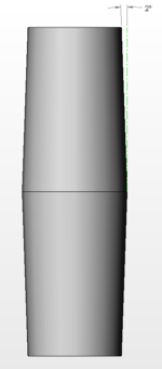
Profile view of a drafted cylinder with the draft dimension 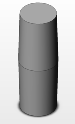
A cylinder with longitudinal draft
Fillet (mechanics)
In mechanical engineering, a fillet /ˈfɪlɪt/ is a rounding of an interior or exterior corner of a part design. An interior or exterior corner, with an angle or type of bevel, is called a "chamfer". Fillet geometry, when on an interior corner is a line of concave function, whereas a fillet on an exterior corner is a line of convex function (in these cases, fillets are typically referred to as rounds). Fillets commonly appear on welded, soldered, or brazed joints.

Parting line
A parting line, in industrial casting of molds, is the border line in which draft angles change direction. That is, it is the dividing line that splits the core and cavity halves of a molded part. It is sometimes a starting point for the mold parting surface. In engineering drawing, parting line is often abbreviated as PL. ASME's Y14.8 standard specifies a symbol for parting line.[1] Engineering applications (seals, tight running molded parts) that require precision for shape control, call for removal of flashes. Many molders will repair or even replace the mold tooling so that the flash is reduced to an acceptable tolerance or eliminated altogether. Secondary operations to remove parting line flash include hand trimming, vibratory tumbling, media blasting and cryogenic deflashing.[2]
디자인 기하학
출처 : https://en.wikipedia.org/wiki/Die_casting
다이캐스팅의 파라 메트릭 모델을 생성 할 때 고려해야 할 여러 기하학적 특징이 있습니다.
- 드래프트 는 다이에서 주물을 쉽게 배출 할 수 있도록 다이 캐비티의 코어 또는 기타 부품에 제공되는 경사 또는 테이퍼의 양입니다. 다이의 개방 방향에 평행한 모든 다이 캐스팅 표면은 다이에서 캐스팅을 적절하게 배출하기 위해 드래프트가 필요합니다. [12] 적절한 드래프트가 특징 인 다이 캐스팅은 다이에서 제거하기가 더 쉬우며 고품질 표면과보다 정밀한 완제품을 만듭니다.
- 필렛 은 날카로운 모서리 또는 가장자리에서 만났을 두 표면의 곡선 접합입니다. 간단히 말해서, 필렛을 다이 캐스팅에 추가하여 원하지 않는 모서리와 모서리를 제거 할 수 있습니다.
- 파팅라인은 금형의 서로 다른 두면이 결합되는 지점을 나타냅니다. 분할 선의 위치는 다이의 어느 쪽이 커버이고 어느 쪽이 이젝터인지를 정의합니다. [13]
- 보스는 장착해야 하는 부품의 스탠드 오프 및 장착 지점으로 사용하기 위해 다이 캐스팅에 추가됩니다. 다이캐스팅의 최대 무결성과 강도를 위해 보스는 보편적 인 벽 두께를 가져야 합니다.
- 리브가 다이 캐스팅에 추가되어 벽 두께를 늘리지 않고 최대 강도가 필요한 설계를 추가로 지원합니다.
- 이러한 형상의 둘레가 응고 중에 다이를 잡기 때문에 다이캐스팅시 구멍과 창을 특별히 고려해야 합니다. 이 부작용을 방지하려면 구멍과 창 피처에 넉넉한 구배를 추가해야 합니다.
Draft (engineering)
드래프트를 위한 테이퍼의 성형양 또는 주조 부품의 수직 파팅 라인으로 각도 또는 mm/mm (in/in) 단위로 측정 할 수 있습니다 .
세로 방향 구배가있는 원통 구배 치수가 있는 구배 원통의 종단 뷰
뚜껑이 없는 속이 빈 플라스틱 상자의 제작을 고려하십시오. 플라스틱이 몰드 주변에서 단단해지면 몰드를 제거해야 합니다. 플라스틱이 굳어지면 약간 수축 할 수 있습니다. 예를 들어 2 ° (2도)와 같이 적절한 "드래프트 각도"로 금형의 측면을 가늘게 함으로써 금형을 쉽게 제거 할 수 있습니다. 이는 해당 사례에서 유리 섬유로 작업 할 때 사용되는 관행입니다.
금형을 상단에서 제거해야 하는 경우 상자가 하단을 향해 테이퍼 져서 하단 내부 치수를 측정하면 금형이 추출되는 상단을 측정하는 것보다 길이와 너비가 더 작아야 합니다.
개구부 길이와 폭, 구배 각도 및 깊이를 지정하면 위에서 계산할 수 있으므로 내부 표면의 치수를 지정할 필요가 없습니다.
양각 또는 음각을 포함하는 부품의 제조에는 주조를 해제하기 위해 두 개 이상의 부품으로 분리 할 수 있는 금형이 필요할 수 있습니다.
기계 공학에서 하는 필렛은 부품 설계도의 내부 또는 외부 모서리의 라운딩을 생성하는 것으로 각도 또는 경사 유형이 있는 내부 또는 외부 모서리를 " 모따기 "라고 합니다. 필렛 지오메트리는 내부 코너에 오목 라인 기능인 반면 외부 코너에 필렛은 볼록 기능 라인입니다 (이 경우 필렛은 일반적으로 라운드라고 함). 필렛은 일반적으로 용접, 납땜 또는 납땜 접합에 나타납니다.
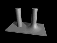
It is common to find a fillet where two parts are welded together Example of a non-filleted pole (left) and a filleted pole (right)
Parting line
파팅라인은 , 산업 주조 금형 , 초안 변화 방향을 각도하는 경계선이다. 즉, 성형 부품의 코어 및 캐비티 절반을 분할하는 구분선입니다. 때로는 금형 분할 표면의 시작점이됩니다. 엔지니어링 도면에서, 분할선은 종종 PL로 축약된다. ASME의 Y14.8 표준은 분할 선에 대한 기호를 지정합니다. [1] 형상 제어를 위해 정밀성을 요구하는 엔지니어링 애플리케이션 (밀봉, 타이트 러닝 성형 부품)에는 플래시 제거가 필요합니다 . 많은 성형기 플래시가 허용 가능한 공차로 감소되거나 완전히 제거되도록 금형 툴링을 수리하거나 교체합니다. 파팅 라인 플래시를 제거하기위한 2 차 작업에는 손 트리밍, 진동 텀블링, 미디어 블라스팅 및 극저온 디플래싱이 포함됩니다. [2]