The content of this introduction paper is based on the article "Automated identification of complex undercut features for side-core design for die-casting parts" published by "SAGE Publications on behalf of the Institution of Mechanical Engineers".
1. Overview:
- Title: Automated identification of complex undercut features for side-core design for die-casting parts
- Author: Ranjit Singh¹,², Jatinder Madan¹,³ and Rajesh Kumar¹
- Year of publication: 2014
- Journal/academic society of publication: Proc IMechE Part B: J Engineering Manufacture / Institution of Mechanical Engineers
- Keywords: Die casting, complex undercut features, feature recognition, side-core design, release direction
2. Abstract:
This article describes automated identification, classification, division and determination of release direction of complex undercut features of die-cast parts. The proposed system uses the concepts of visibility and accessibility to identify undercut features from a B-rep model of a die-casting part. The undercut features are then classified using a rule-based algorithm. Thereafter, the identified complex undercut features are separated into simple ones. Finally, the release direction for each simple undercut feature is determined and those having common release direction are grouped. The proposed system is implemented on case study die-cast parts, and the results are verified. This article would help bridge the design-manufacturing integration gaps in the die-casting process.
3. Introduction:
Die casting is a manufacturing process involving the injection of molten metal under pressure into a permanent metal mould (die), typically comprising a movable core half and a stationary cavity half. After solidification, the core disengages, and the part is removed. The process often yields parts requiring minimal secondary operations. Key terminology includes:
- Parting direction: The direction of disengagement of die halves, with core movement defined as positive parting direction (+k) and the opposite as negative parting direction (-k).
- Parting line: The seam on the part corresponding to the die joint.
- Feature: An identifiable region or attribute of a part (e.g., design, machining, die-casting feature).
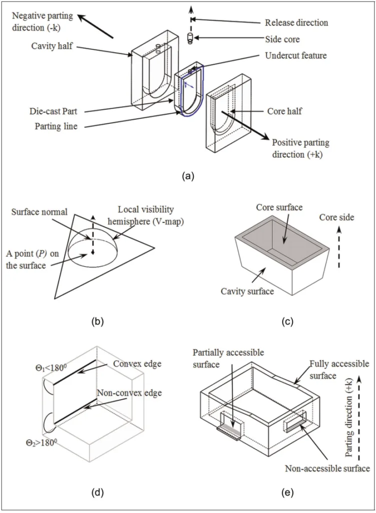
- Undercut feature: A geometric region inaccessible from either the positive or negative parting directions (Figure 1(a)).
- Side-core: Special tooling used to mould undercut features (Figure 1(a)).
- Side-core release direction: The direction of side-core movement during disengagement (Figure 1(a)).
- Local visibility: The direction a point on a surface is visible, represented by its normal and visibility map (V-map) (Figure 1(b)).
- Core/Cavity surfaces: Part surfaces moulded by the core/cavity halves, respectively (Figure 1(c)).
- Convex/Non-convex edges: Edges where the angle between adjoining surfaces (measured from the material side) is less than or greater than 180°, respectively (Figure 1(d)).
Die design involves critical activities like identifying undercut features, which significantly impacts lead time, cost, parting line determination, and core-cavity design. Side-cores are designed subsequent to undercut identification. Traditionally performed manually by experts using CAD software, undercut feature recognition represents a gap in design-manufacturing integration. This research aims to bridge this gap by proposing automated methods for identifying complex undercut features and dividing them into simple features to facilitate side-core design.
4. Summary of the study:
Background of the research topic:
The design of die-casting dies is a complex process where the identification of undercut features is a critical step. These features necessitate special tooling (side-cores) and influence fundamental design decisions like parting line placement and core/cavity geometry. Automating this identification process is crucial for improving efficiency and integration in die casting.
Status of previous research:
Previous research in feature identification from CAD models, particularly for die casting and mould design, has employed various techniques like visibility maps, spherical maps, graph-based methods, block factor, grid line/column insertion tests, 3D ray detection, freedom cones, non-directional blocking graphs, graphics hardware acceleration, polyhedron face adjacency graphs, and geometric/topological analysis. Researchers (e.g., Dhaliwal et al.⁷, Surti and Reddy⁸, Liu and Ramani⁹, Chen¹⁰, Hui and Tan¹¹, Wong et al.¹², Fu et al.¹³, Lu and Lee¹⁴, Yin et al.¹⁵, Ye et al.¹⁶,¹⁷, Khardekar et al.¹⁸, Banerjee and Gupta¹⁹, Kumar et al.²⁰, Madan et al.²¹, Fu²², Madan et al.²³, Huang²⁴, Bidkar and McAdams²⁵, Bassi et al.²⁶, Kumar et al.³, Ran and Fu²⁷) have focused on detecting undercuts, determining release directions, generating parting lines/surfaces, and recognizing mould features. However, a review (summarized partially in Table 1) indicates significant research gaps.
Purpose of the study:
This study aims to address the identified gaps in previous research concerning complex undercut features. The specific objectives are:
- Identifying complex undercut features of the die-cast part.
- Classifying complex undercut features.
- Dividing the identified complex undercut features into simple features.
- Determining the release direction of the simple undercut features.
Core study:
The core of this study is the development and implementation of a system for the automated identification, classification, division, and release direction determination of complex undercut features in die-cast parts represented by B-rep models. It utilizes concepts of visibility and accessibility to first identify undercut surfaces. A rule-based algorithm then classifies these features. Methodologies are proposed to divide complex undercuts (specifically unbounded, intersecting with other undercuts, and intersecting with mouldable regions, assuming planar surfaces) into simpler features. Finally, the system determines the appropriate release direction for each simple undercut feature and groups those sharing a common direction, facilitating subsequent side-core design.
5. Research Methodology
Research Design:
The research employs an algorithmic approach based on the geometric and topological analysis of a die-cast part's Boundary Representation (B-rep) model. The methodology follows a structured sequence:
- Surface classification based on local visibility relative to the parting direction.
- Identification of Non-Convex Regions (NCRs) formed by connected Non-Convex Surfaces (NCSs) and Non-Convex Edges (NCEs).
- Determination of surface accessibility (fully accessible, non-accessible, partially accessible) in the parting direction using an algorithm adapted from Singh and Madan [2].
- Identification of undercut surfaces (non-accessible patches and specific types of partially accessible patches) using the algorithm detailed in Figure 5.
- Classification of identified undercut features into simple and complex types (e.g., blind depression, through depression, unbounded, nested) based on geometric characteristics (Figure 6, Figure 7).
- Division of specific complex undercut features (unbounded, intersecting) with planar surfaces into simple features using surface patch creation techniques (Figure 8, Figure 9, Figure 10).
- Determination of the release direction for each simple undercut feature by checking accessibility against candidate release directions (Figure 11, Figure 12).
- Grouping of simple undercut features sharing a common release direction.
Data Collection and Analysis Methods:
Input data consists of a B-rep file of the die-cast part and a user-specified positive parting direction (+k). Geometric analysis relies heavily on:
- Dot Product (DP): Used for classifying surfaces (up, down, neutral) based on surface normal (ni) and parting direction (k) (DP = ni · k), and for checking accessibility in candidate release directions (RDi) (DP = ni · RDi).
- Accessibility Algorithm: An algorithm (based on Singh and Madan [2]) checks for obstruction by other surfaces within the same NCR to determine if a surface is fully accessible, non-accessible, or partially accessible in the parting direction.
- Geometric Feature Recognition: Identifying NCEs, NCSs, NCRs, convex edge loops, and common edges between surfaces.
- Surface Patch Creation: Generating new surfaces (patches) based on edge extensions or loop boundaries to divide complex features (as shown in Figures 8, 9, 10).
- Rule-Based Classification: Applying rules based on edge loop types (convex, NCE) and intersections to classify undercut features (Figure 6, Figure 7).
The methodology was implemented and verified using case study die-cast parts (Figure 13, Figure 14).
Research Topics and Scope:
The research focuses specifically on the automated identification, classification, division, and release direction determination for complex undercut features in die-cast parts, intended to support side-core design. The scope is defined by the following assumptions and limitations:
- The die-casting part is assumed to be mouldable.
- The primary parting direction (+k) is provided as input.
- The methodologies for dividing complex undercut features are developed and demonstrated primarily for features involving planar surfaces only.
- The study addresses specific types of complex features: unbounded, intersecting with other undercut features, and intersecting with mouldable regions.
6. Key Results:
Key Results:
The study successfully developed and demonstrated a system capable of:
- Automated Identification: Identifying complex undercut features from a B-rep model using accessibility analysis relative to the parting direction.
- Classification: Classifying identified undercut features based on a defined typology (Figure 6), distinguishing between simple and various complex types (e.g., unbounded, intersecting, nested - Figure 7).
- Division: Dividing complex undercut features (unbounded, intersecting with planar surfaces) into multiple simple undercut features using geometric operations like surface patch creation (Figures 8, 9, 10). Each resulting simple feature possesses a unique withdrawal direction.
- Release Direction Determination: Determining the appropriate release direction (RD) for each simple undercut feature by evaluating candidate directions based on surface accessibility (Figures 11, 12).
- Grouping: Grouping simple undercut features that share a common release direction, providing essential information for designing common side-cores.
Implementation on example parts (Figure 13, Figure 14) validated the methodology, showing the process from complex feature identification to the division into simple features with assigned release directions (RD1, RD2, etc.). The system offers a significant time reduction compared to manual methods (1-2 minutes vs. 30-40 minutes reported). The results facilitate automation in die design and enhance design-manufacturing integration. While demonstrated on specific planar geometries, the underlying algorithm is considered generic and potentially adaptable to other shapes with minor modifications.
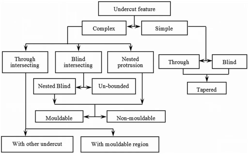
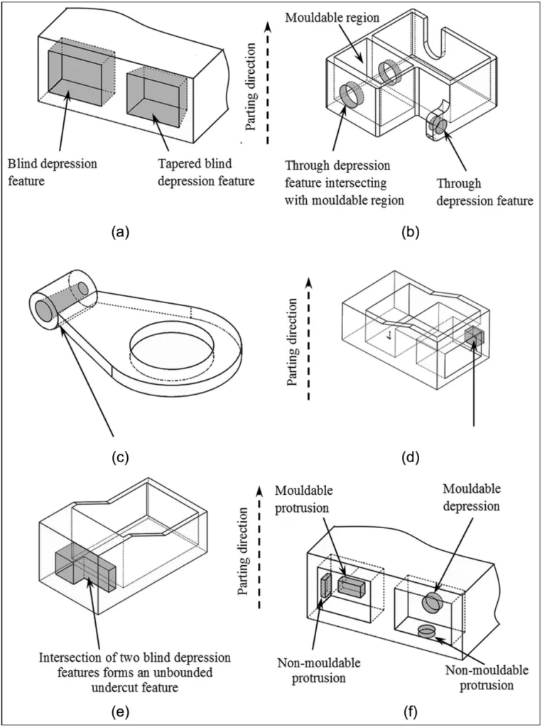
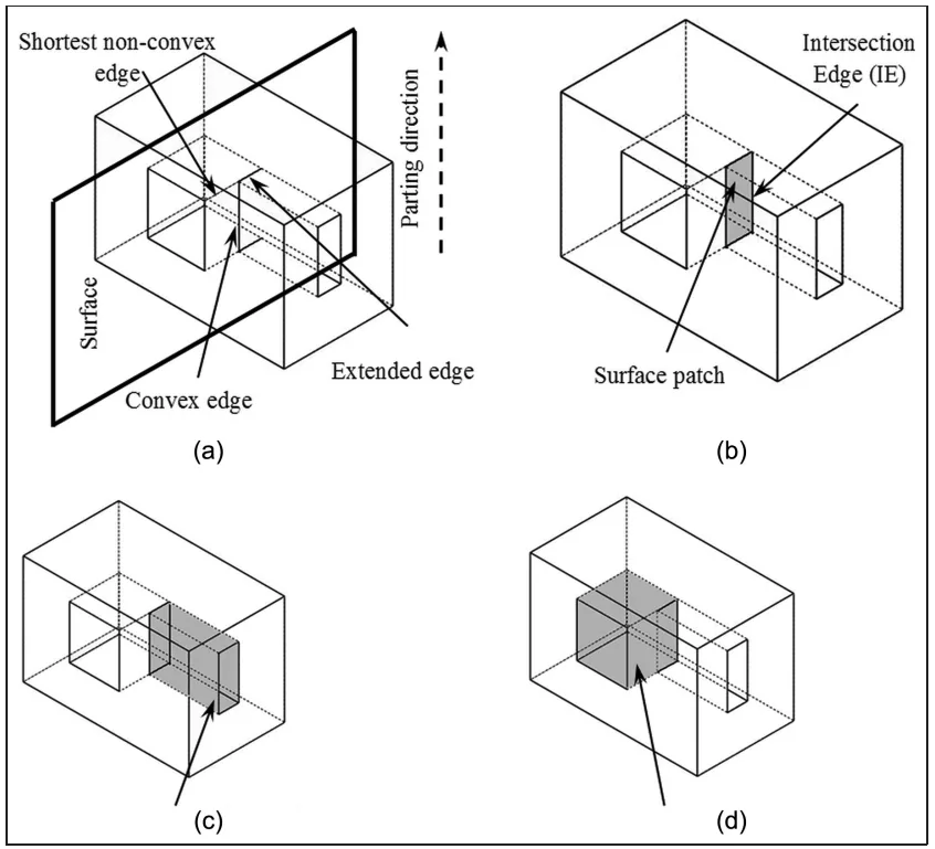
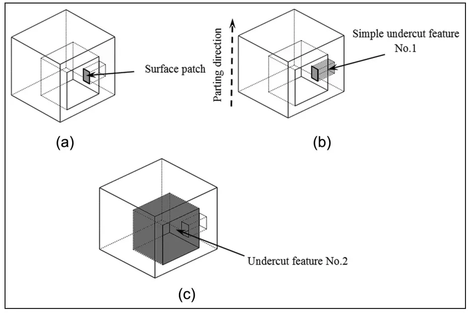
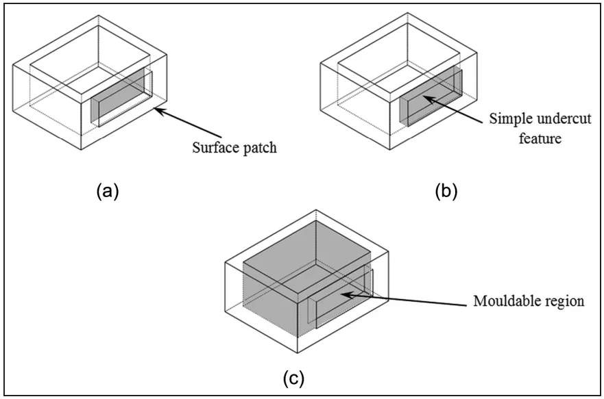
Figure Name List:
- Figure 1. Pictorial representation of the die-casting die terminology: (a) an exploded view of a typical die-casting die, (b) local visibility of a surface, (c) core and cavity surfaces, (d) classification of edges and (e) classification of surfaces.
- Figure 2. Classification of surfaces of a die-cast part.
- Figure 3. A schematic of a non-convex region: (a) non-convex edges (NCE) and non-convex surfaces (NCS) and (b) non-convex region.
- Figure 4. Mouldability of the partially accessible surfaces. (a) Accessible patch inside the boundary of a non-accessible patch, (b) accessible surface patch outside non-accessible surface patch and (c) determining mouldability of the surface patches.
- Figure 5. Information flow diagram for identification of undercut features.
- Figure 6. Classification tree of die-casting undercut features.
- Figure 7. Instances of undercut features: (a) blind undercut features, (b) through undercut features, (c) tapered through depression features, (d) through depression feature intersecting with the undercut region, (e) unbounded undercut feature and (f) nested depression and protrusion features.
- Figure 8. Division of unbounded undercut feature: (a) extension of shortest non-convex edges, (b) creating a surface patch, (c) simple undercut feature No. 1 and (d) simple undercut feature No. 2.
- Figure 9. Division of complex intersecting undercut feature: (a) creating a surface patch bounded by the convex edge loop, (b) an instance of division of a complex undercut feature and (c) division of undercut feature intersecting with another undercut feature.
- Figure 10. Division of undercut feature and intersecting mouldable region: (a) creating a surface patch bounded by the convex edge loop, (b) identification of simple undercut feature intersecting with mouldable region and (c) identification of mouldable region intersecting with undercut feature.
- Figure 11. Information flow diagram for determination of release direction of a simple undercut feature. RD: release direction; DP: dot product.
- Figure 12. Determination of release direction.
- Figure 13. Results for example part No. 1: (a) part model with complex undercut features, (b) division of complex undercut features and (c) side-core with release direction. RD: release direction.
- Figure 14. Results for example part No. 2: (a) part model with complex undercut features, (b) division of complex undercut features and (c) side-cores with release direction. RD: release direction.
7. Conclusion:
A system for the automated recognition of complex undercut features for side-core design in die-cast parts has been developed. This system addresses features that lack a single withdrawal direction relative to the main parting direction. It provides a novel method to identify, classify, and crucially, separate complex undercut features into multiple simple undercut features. Each resulting simple feature is assigned its own unique withdrawal (release) direction. Furthermore, the system groups simple features sharing a common withdrawal direction, which is essential input for designing efficient common side-cores.
The proposed system was implemented and tested on die-cast parts exhibiting complex undercut features with planar surfaces, and the results were verified with industry practices. While demonstrated on specific geometries, the core algorithm is generic and applicable to other feature shapes, potentially requiring slight modifications. A significant benefit is the drastic reduction in time required for these tasks compared to manual expert methods (1-2 minutes versus 30-40 minutes). This system facilitates the automation of the die design process by reducing lead times, generating critical information for downstream activities like core, cavity, and side-core design, and ultimately contributing to better design-manufacturing integration in the die-casting industry.
8. References:
- [1] Kalpakjian S and Schmid SR. Manufacturing engineering and technology. 4th ed. New Delhi: Pearson Education, 2011.
- [2] Singh R and Madan J. Systematic approach for automated determination of parting line for die-cast parts. Robot Cim: Int Manuf 2013; 29: 346–366.
- [3] Kumar V, Madan J and Gupta P. A system for design of multicavity die casting dies from part product model. Int J Adv Manuf Tech 2013; 67: 2083–2107.
- [4] Gan GH, Woo TC and Tang K. Spherical maps: their construction, properties and approximation. J Mech Des: T ASME 1994; 116: 357–363.
- [5] Elber G and Cohen E. Arbitrarily precise computation of Gauss maps and visibility sets for freeform surface. In: Proceedings of the third ACM symposium on solid modeling and applications (SMA ‘95), Salt Lake City, UT, 17–19 May 1995, pp.271–279. New York: ACM.
- [6] Fuh JYH, Wu SH and Lee KS. Development of a semi-automated die casting die design system. Proc IMechE, Part B: J Engineering Manufacture 2002; 216: 1575–1588.
- [7] Dhaliwal S, Gupta SK, Huang J, et al. Algorithms for computing global accessibility cones. J Comput Inf Sci Eng 2003; 3(3): 200–209.
- [8] Surti A and Reddy NV. Non-discretized approach to visibility analysis for automatic mold feature recognition using step part model. J Adv Manuf Syst 2012; 12(1): 1–16.
- [9] Liu M and Ramani K. Computing an exact spherical visibility map for meshed polyhedral. In: Proceedings of the 2007 ACM symposium on solid and physical modelling, Beijing, China, 4–6 June 2007, pp.367–372. New York: ACM.
- [10] Chen YH. Determination of parting direction based on minimum bonding box and fuzzy logic. Int J Mach Tool Manu 1997; 37(9): 1189–1199.
- [11] Hui KC and Tan ST. Mould design with sweep operations – a heuristic search approach. Comput Aided Design 1992; 24(2): 81–92.
- [12] Wong T, Tan ST and Sze WS. Parting line formation by slicing a 3D CAD model. Eng Comput 1998; 14: 330–343.
- [13] Fu MW, Fuh JYH and Nee AYC. Generation of optimal parting direction based on undercut features in injection moulded parts. IIE Trans 1999; 31: 947–955.
- [14] Lu HY and Lee WB. Detection of interference elements and release directions in die-cast and injection-moulded components. Proc IMechE, Part B: J Engineering Manufacture 2000; 214(6): 431–441.
- [15] Yin Z, Ding H and Xiong Y. Virtual prototyping of mould design: geometric mouldability analysis for near net shape manufactured parts by feature recognition and geometric reasoning. Comput Aided Design 2001; 33: 137–157.
- [16] Ye XG, Fuh JYH and Lee KS. A hybrid method for recognition of undercut features from moulded parts. Comput Aided Design 2001; 33: 1023–1034.
- [17] Ye XG, Fuh JYH and Lee KS. Automatic undercut feature recognition for side core design of injection molds. J Mech Design 2004; 126(3): 519–526.
- [18] Khardekar R, Burton G and McMains S. Finding feasible mold parting directions using graphics hardware. Comput Aided Design 2006; 38: 327–341.
- [19] Banerjee AG and Gupta SK. Geometrical algorithms for automated design of side actions in injection moulding of complex parts. Comput Aided Design 2007; 39: 882–897.
- [20] Kumar N, Ranjan R and Tiwari MK. Recognition of undercut features and parting surface of moulded parts using polyhedron face adjacency graph. Int J Adv Manuf Tech 2007; 34(1–2): 47–55.
- [21] Madan J, Rao PVM and Kundra TK. Die-casting feature recognition for automated parting direction and parting line determination. J Comput Inf Sci Eng 2007; 7(3): 236–248.
- [22] Fu MW. The application of surface demoldability and moldability to side-core designing die and mold CAD. Comput Aided Design 2008; 40: 567–575.
- [23] Madan J, Singh A and Kumar S. Recognition of intersecting features and identification of separable regions for design-manufacturing integration. In: Proceedings of the international conference on digital factory (ICDF), Trichy, India, 11–13 August 2008, pp.60–67.
- [24] Huang TS. Algorithms for recognizing undercut feature. J Technol 2008; 23(1): 61–69.
- [25] Bidkar RA and McAdams DA. Methods for automated manufacturability analysis of injection-molded and die-cast parts. Res Eng Des 2010; 21: 1–24.
- [26] Bassi R, Reddy NV and Bedi S. Automatic recognition of intersecting features for side-core design in two piece permanent molds. Int J Adv Manuf Tech 2010; 50: 421–439.
- [27] Ran JQ and Fu MW. Design of internal pins in injection mold CAD via the automatic recognition of undercut features. Comput Aided Design 2010; 42(7): 582–597.
- [28] Sunil VB and Pande SS. Automatic recognition of features from freeform surface CAD models. Comput Aided Design 2008; 40: 502–517.
- [29] Tan ST, Yuen MF, Sze WS, et al. Parting lines and parting surfaces of injection moulded parts. Proc IMechE, Part B: J Engineering Manufacture 1990; 204: 211–221.
9. Copyright:
- This material is a paper by "Ranjit Singh, Jatinder Madan and Rajesh Kumar". Based on "Automated identification of complex undercut features for side-core design for die-casting parts".
- Source of the paper: https://doi.org/10.1177/0954405413514744
This material is summarized based on the above paper, and unauthorized use for commercial purposes is prohibited.
Copyright © 2025 CASTMAN. All rights reserved.