International Journal of Precision Engineering and Manufacturing volume 13, pages2251–2257 (2012)Cite this article
Abstract
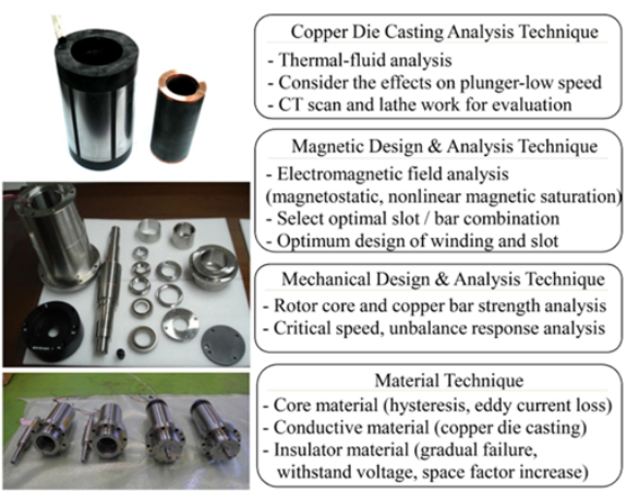
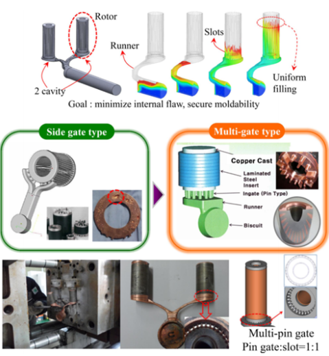
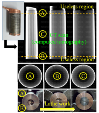
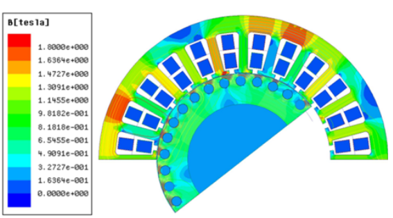
This paper deals with the analysis techniques of a high speed and high efficiency 10 kW, 30,000 rpm rated induction motor. The induction motor has been analyzed by time-varying magnetic finite element method and the test results show that there is a possibility that the motor could be used in a high speed spindle system application. All performances of the prototype are successfully verified. All analysis techniques are introduced to develop a high speed and high efficiency induction motor of copper die casting. The analysis techniques are composed of an electrical technique (magnetic analysis), and a mechanical technique (casting analysis, structural analysis, critical speed analysis and unbalance response analysis). Simulation results are compared with the experiment, and are within a 3% deviation.
Abstract Korea
본 논문은 10kW, 30,000rpm 정격의 유도전동기에 대한 고속·고효율의 해석기법을 다룬다. 유도 전동기는 시변 자기 유한 요소법으로 해석되었으며 시험 결과 고속 스핀들 시스템 응용 분야에서 전동기가 사용될 가능성이 있음을 보여줍니다. 프로토타입의 모든 성능이 성공적으로 검증되었습니다. 구리 다이캐스팅의 고속, 고효율 유도 전동기를 개발하기 위해 모든 해석 기술이 도입되었습니다. 해석기법은 전기적 기법(자기해석)과 기계적 기법(주조해석, 구조해석, 임계속도해석, 불평형응답해석)으로 구성된다. 시뮬레이션 결과는 실험과 비교되며 3% 편차 이내입니다.


References
- 1.Peters, D. T., Cowie, J. G., Brush, E. F., and Midson, S. P., “Advances in Pressure Die Casting of Electrical Grade Copper,” Amer. Foundry Society Congress, 2002.
- 2.Peters, D. T., Cowie, J. G., Brush, E. F., and Midson, S. P., “Use of High Temperature Die Materials and Hot Dies for High Pressure Die Casting Pure Copper and Copper Alloys,” Trans. of the North Amer. Die Casting Assoc. Congress, 2002.
- 3.Deivasahayam, M., “Energy Conservation through Efficiency Improvement in Squirrel Cage Induction Motors by Using Copper Die Cast,” International Conference of Energy Efficiency in Motor Driven Systems (EEMODS’05), Vol. I, pp. 92–101, 2005.Google Scholar
- 4.Haataja, J. and Pyrhonen, J., “Improving three-phase induction motor efficiency in Europe,” Power Engineering Journal, Vol. 12, pp. 81–86, 1998.Article Google Scholar
- 5.Lie, S. and Di Pietro, C., “Copper Die-Cast Rotor Efficiency Improvement and Economic Consideration,” IEEE Transactions of Energy Conversion. Vol. 10, No. 3, pp. 419–424, 1995.Article Google Scholar
- 6.Malinowski, J., McCormick, J., and Dunn, K., “Advances in Construction Techniques of AC Induction Motors: Preparation for Super-Premium Efficiency Levels,” IEEE Transactions of Industry Applications, Vol. 40, No. 6, pp. 1665–1670, 2004.Article Google Scholar
- 7.Honsinger, V. B., “Sizing equations for electrical machinery,” IEEE Trans. on Energy Conversion, Vol. EC-2, No. 1, pp. 116–121, 1987.Article Google Scholar
- 8.Boldea, I. and Nasar, S. A., “The Induction Machine Handbook,” CRC Press, 2002.
- 9.Veinott, C. G., “Theory and Design of Small Induction Motors,” McGraw-Hill Book, 1959.
- 10.IEEE Std. 112, “IEEE Standard Test Procedure for Poly phase Induction Motors and Generators,” 2004.
- 11.IEC 60034-2-1, “Standard methods for determining losses and efficiency from tests (excluding machines for traction vehicles,” 2007.
- 12.Agamloh, E. B., “An Evaluation of Induction Machine Stray Load Loss From Collated Test Results,” IEEE Trans. on Industry App., Vol. 46, No. 6, pp. 2311–2318, 2010.Article Google Scholar
- 13.Hong, D. K., Woo, B. C., and Koo, D. H., “Rotordynamics of 120,000 r/min 15 kW Ultra High Speed Motor,” IEEE Trans. Magn., Vol. 45, No. 6, pp. 2831–2834, 2009.Article Google Scholar
- 14.Lalanne, M. and Ferraris, G., “Rotordynamics prediction in engineering,” Wiley, 1998.
- 15.Chen, W. J. and Gunter, E. J., “Introduction to dynamics of rotorbearing systems,” Eigen Technologies, 2005.
- 16.Na, U. J., “Design and Analysis of a New Permanent Magnet Biased Integrated Radial-Axial Magnetic Bearing,” Int. J. Precis. Eng. Manuf., Vol. 13, No. 1, pp. 133–136, 2012.MathSciNet Article Google Scholar
- 17.ISO 1940-1, “Mechanical vibration-balance quality requirement for rotors in a constant (rigid) state,” 2003.
- 18.API Standard 611, “General-purpose Steam Turbines for Petro-leum, Chemical, and Gas Industry Services,” Fifth Edition, American Petroleum Institute, 2008.
- 19.Ganatra, N. and Ratel, R. C., “Witness Testing of API 610 Centrifugal Pumps and API 611 Steam Turbines,” Proc. of the 27th International Pump Users Symposium, pp. 71–79, 2011.
- 20.Hong, D. K., Woo, B. C., Lee, J. Y., and Koo, D. H., “Ultra High Speed Motor Supported by Air Foil Bearings for Air Blower Cooling Fuel Cells,” IEEE Trans. Magn., Vol. 48, No. 2, pp. 871–874, 2012.Article Google Scholar
- 21.Hong, D. K., Woo, B. C., and Koo, D. H., “Rotordynamics and Unbalance Response Analysis of 200 kW, 15 krpm, 3 Phase Induction Motor,” Przeglad Elektrotechniczny, Vol. 86, No. 5, pp. 129–132, 2010.Google Scholar
Keywords
- Casting analysis
- Magnetic analysis
- CT scan
- Copper die casting high speed Induction motor for spindle
- Critical speed analysis
- Unbalance response analysis