by Iban Vicario 1,*,Ignacio Crespo 2,†,Luis Maria Plaza 2,Patricia Caballero 1,† andIon Kepa Idoiaga 3,‡1Department of Foundry and Steel making, Tecnalia Research & Innovation, c/Geldo, Edif. 700, E-48160 Derio, Spain2Department of Aerospace, Tecnalia Research & Innovation, c/Mikeletegi 2, E-20009 Donostia, Spain3Industrias Lebario, c/Arbizolea 4, E-48213 Izurza, Spain*Author to whom correspondence should be addressed.†These authors contributed equally to this work.‡This author supervised this work.Academic Editor: Hugo F. LopezMetals2016, 6(1), 24; https://doi.org/10.3390/met6010024Received: 9 November 2015 / Revised: 23 December 2015 / Accepted: 11 January 2016 / Published: 15 January 2016
Abstract
Nowadays, fuel consumption and carbon dioxide emissions are two of the main focal points in vehicle design, promoting the reduction in the weight of vehicles by using lighter materials. The aim of the work is to evaluate the influence of different aluminium foams and injection parameters in order to obtain compound castings with a compromise between the obtained properties and weight by high-pressure die cast (HPDC) using aluminium foams as cores into a magnesium cast part. To evaluate the influence of the different aluminium foams and injection parameters on the final casting products quality, the type and density of the aluminium foam, metal temperature, plunger speed, and multiplication pressure have been varied within a range of suitable values. The obtained compound HPDC castings have been studied by performing visual and RX inspections, obtaining sound composite castings with aluminium foam cores. The presence of an external continuous layer on the foam surface and the correct placement of the foam to support injection conditions permit obtaining good quality parts. A HPDC processed magnesium-aluminium foam composite has been developed for a bicycle application obtaining a suitable combination of mechanical properties and, especially, a reduced weight in the demonstration part.
더 가벼운 재료를 사용하여 차량의 무게 감소를 촉진합니다. 이 작업의 목적은 알루미늄 폼을 마그네슘 캐스트의 코어로 사용하는 고압 다이 캐스트(HPDC)로 얻은 부품 특성과 무게 사이의 절충안이 있는 복합 주물을 얻기 위해 다양한 알루미늄 폼과 사출 매개변수의 영향을 평가하는 것입니다.
최종 주조 제품 품질에 대한 다양한 알루미늄 폼 및 사출 매개변수의 영향을 평가하기 위해 알루미늄 폼의 유형 및 밀도, 금속 온도, 플런저 속도 및 증배 압력을 적절한 값 범위 내에서 변경했습니다.
얻어진 복합 HPDC 주물은 육안 및 RX 검사를 수행 연구하여 알루미늄 폼 코어가 있는 건전한 복합 주물을 얻었습니다. 발포체 표면에 외부 연속층이 존재하고 사출 조건을 지원하기 위해 발포체를 올바르게 배치하면 우수한 품질의 부품을 얻을 수 있습니다.
HPDC 처리된 마그네슘-알루미늄 폼 복합재는 기계적 특성의 적절한 조합, 특히 시연 부분에서 감소된 중량을 얻기 위해 자전거 용도로 개발되었습니다.
Keywords: high pressure die casting (HPDC); hybrid magnesium aluminium foam cast composite; aluminium foam core; magnesium cast composite
1. Introduction
The need of decreasing the weight of the components in the transport industry [1] by the substitution of steel and iron casting components by plastics, carbon fiber, or aluminium and magnesium alloys has become one of the major boosters for transport industries. In the case of the bicycle industry, the substitution of materials such as steel, aluminium, and titanium by carbon fiber for high performance bicycles is a clear tendency.Magnesium components produced by HPDC are already used for many automotive and bike applications, but the industry continues to look for new parts where the balance of lightness and mechanical properties provided by magnesium-lightened structures may be a solution. HPDC is a high-productivity process that is economically feasible for large production series (more than about 5000–10,000 parts/year) [2], where the high cost of production dies are paid off. In HPDC, the molten metal is poured into a steel shot sleeve. Then the metal is forced to enter into a closed metallic die under high metal velocities (from about 30 to 100 m/s for magnesium alloys) [3] and high dimensional accuracy complex components are produced, presenting a low surface roughness by the subsequent extremely short filling time (from 10 to 150 ms approx.) [4,5]. During solidification the metal contracts and can produce shrinkage porosity in the casting. To solve this physical phenomenon, metal is pressed in the liquid or semi-solid state using high pressures into the die cavity (specific pressures over the injected part of about 60 to 100 MPa). Steel dies can be designed to obtain very complex geometries and the total cycle time of the process is usually lower than 60 s.However, HPDC is a complex process due to the large amount of parameters that influence the final casting quality. There are multiple parameters independent and interdependent that can have influence over the final part quality [6]. The main parameters that affect the mechanical properties of HPDC components are related to injection parameters (pressures, speeds, starting points) and die temperatures, but there are other essential aspects such as the castability of the alloy, the geometrical complexity of the parts, the cooling rate, and the type of equipment used to produce the components that affect the soundness and properties of injected parts. There are other parameters that affect the flow and solidification behavior of the cast parts as the viscosity and the gate, runner, and mold cavity design [7]. In order to maintain a stable die temperature, cooling and tempering circuits are employed, but to obtain a good quality part the lubrication of the die should also be adjusted to the selected alloy, working temperatures, and cycle time. They are several types of lubricants (water-based, oil-based, or dry lubricants), that should be selected for a determined application [8,9,10]. The quantity and percentage of lubricant should also be adjusted to the process for avoiding quality defects.The HPDC process also presents some drawbacks. The main negative aspect is related to the internal porosity of the components, mainly derived from the turbulent flow in which the molten metal is forced to get into the die. This aspect renders HPDC components more difficult to be heat-treated and the mechanical properties attainable are, therefore, lower than those obtained in other casting processes. Contamination of the alloy by deposits of lubricants and oxides, and problems related to high maintenance costs of the dies submitted to cavitation, wear, and soldering phenomena are additional drawbacks hindering the use of HPDC for the production of highly structural components [11,12]. Several strategies have been followed to try to improve the performance of HPDC components in recent years. New HPDC variants have been developed with the aim of reducing the intrinsic porosity of conventional HPDC components.In order to decrease the weight of injected parts different strategies have been employed. One is the employ of aluminium-magnesium composites [13], but their applications are quite exotic. One of the best known examples of aluminium-magnesium composite is the BWM aluminium-magnesium block [14] where magnesium is cast over the aluminium core. However, no metallurgical bonding is obtained due to the alumina surface of the aluminium core [15] if the aluminium core is not pre-treated with a special surface layer.Another way is by obtaining hollow parts by HPDC using salt cores. However, it is difficult to eliminate the salt core, and also some holes in the parts are necessary to eliminate the salt from the cast part [16,17,18].The development of new alloys for HPDC with improved properties can also reduce the total weight of the injected parts, by using different alloying elements and compositions [19].One of the main challenges of obtaining composite castings with aluminium foam cores is to prevent the deformation or crash of the cores, due to the high velocity and specific pressures employed in the HPDC and also the necessity of avoiding defects on the casting.Among these advances, the development of aluminium foams has a special importance [20]. Three main methods of producing aluminium foams are presented in the market. In Figure 1 we can observe some of the most important process used to produce aluminium foams [21,22,23].
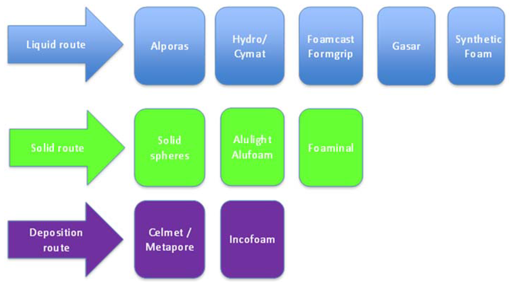
Figure 1. Some of the most employed processes to produce aluminium foams.Every method has its advantages and disadvantages, which are summarized in Table 1.Table 1. Pros and cons of different foams production routes.

Only a few processes can be employed to obtain foams with complex shapes and an external aluminium skin. One process is to overcast aluminium foam by low-pressure die casting (LPDC). We can obtain aluminium foam sandwich structures with an inner permanent core of aluminium foam and a dense aluminium outer skin with a thickness of several millimetres [24].A different possibility is to employ the integral foaming molding process [IFM], which is a very interesting process applicable to LPDC and HPDC, and for both aluminium and magnesium alloys [25]. The main advantage is that we can obtain not only aluminium but also magnesium foams. However, the processed HPDC part has a non-skinned area of the total length of the movement of the cores, and there are limitations in the part geometry. Additionally, dies are more complex and their maintenance more expensive.In the last years, a novel process named advanced pore morphology (APM) has been developed to obtain composites with aluminium, based on the use of aluminium foam spheres as the material to obtain the aluminium foam core. This process is expensive and it is quite complicated to obtain a good interphase between the aluminium foam spheres [26].The approach used in the present work has also been related to the analysis and control of the HPDC parameters to obtain good quality parts. The final objective was to develop a process that could be used for the production of a bicycle rod currently produced by forging aluminium, titanium, or magnesium, or by using carbon fibers. In Figure 2 we can observe the objective component after having been redesigned to be adapted to HPDC features.
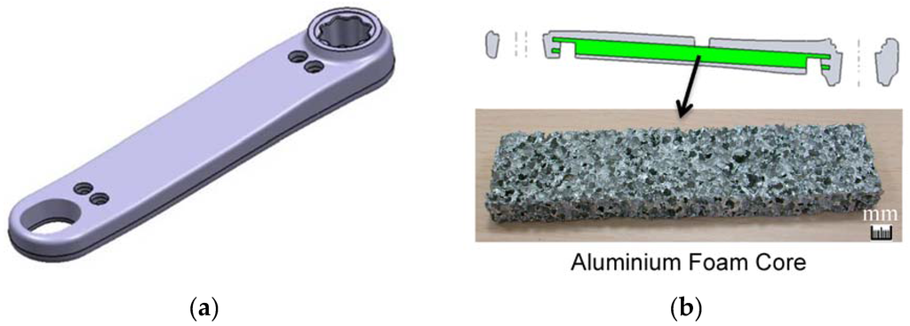
Figure 2. (a) 3D rod design; and (b) detail of the placement and example of an aluminium foam core.The developed composite casting has to comply with the established mechanical requirements, but with the reduction of cast part total weight at a competitive production cost as the main objective. In the present study three different close pore aluminium foams types were used to validate the aluminium foam as a core to be overcast with an AM60B alloy. The selected close pore aluminium foams were the Alporas ALPO-PLA-03 [27,28], a Formgrip-based processed foam [29,30] and the 0.4% TiB2 AlSi12 Alulight foam [31,32,33,34].The results here presented are a part of a work aimed to obtain a light new high-performance bicycle rod. The work consists of validating the development of a HPDC magnesium AM60B alloy with an aluminium foam core, presenting a remarkable reduction in weight to be employed in transport and sport.
2. Experimental Section
Castings were produced with an AM60B alloy and three different aluminium foam cores. Table 2 presents the main properties to be obtained and Table 3 presents the composition of the base alloy.Table 2. Requirements established for magnesium-aluminium foam-based rod.

Table 3. Base composition of the AM60B alloy.

Three different aluminium foams were used in the project. Alporas-type foams were developed by the liquid route to obtain low density foams by Alcan. ALPO-PLA-03 aluminium foams with densities ranging from 0.25 to 0.4 Kg/dm3 were selected with a range of 10% of carbon silicide particles. In this foam there is no external aluminium skin, and it is very difficult to obtain complex shapes. The second type of foams were fabricated at Tecnalia using the Formgrip process, by adding carbon silicide and titanium hydride particles of less than 10−4 µm to an AlSi7 and AlCSi aluminium molten alloys. The Formgrip process promotes the formation of close porous material but with a more expensive and complicated process in comparison with others. The process is based in adding foaming powders as precursors of gas porosity and stabilizing the created porous foam by heat treatment. The foaming temperatures were established between 680 °C and 720 °C.The last type of foams employed in the trials was the Alulight 0.4 TiB2 AlSi12 alloy. In this alloy the content of silicon is adjusted to improve castability and mechanical strength values [35].For making the Alulight type foams, a metallic die was prepared and the foaming process was studied to obtain soundness of aluminium core foams, studying the quantity of the precursor, the die temperature, the furnace temperature, and the residence time, obtaining a density range a from 0.54 to 1.55 Kg/dm3.In Figure 3 we can observe the metallic die employed to obtain the Alulight samples.
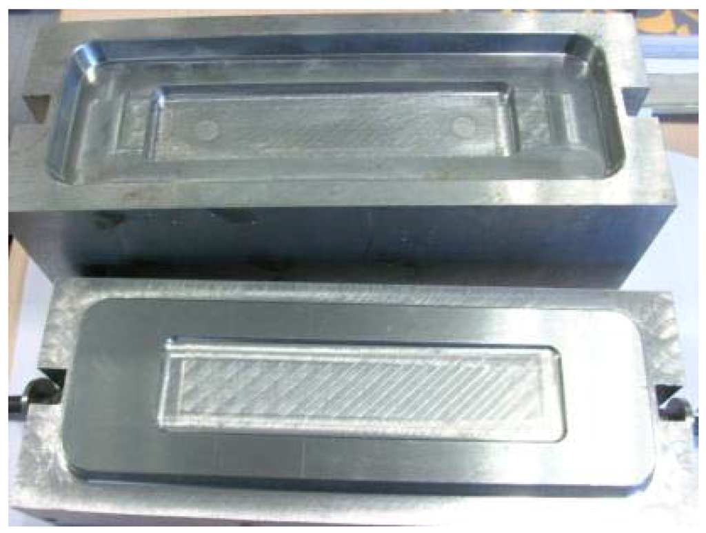
Figure 3. Metallic die to produce Aluminium foams with Alulight.Different essays at 600, 650, and 670 °C, respectively, were developed to determine the residence time of the Alulight precursor inside the die to obtain the final aluminium foam insert. After the study of the foaming parameters, a manufacturing procedure was established. The die was first heated to 670 °C, after the die was opened, the precursor was placed on the die cavity, the die was closed, and then introduced into the furnace. After 6 min of residence time, the die was extracted from the furnace, opened, and the final foam extracted.The obtained density varied from 0.25 to 0.4 Kg/dm3 for Alporas samples, from 0.4 to 0.65 Kg/dm3 for Formgrip samples, and 0.54 to 1.55 Kg/dm3 for the Alulight samples.In order to determine the castability of the composite component, a molten AM60B magnesium alloy was poured over the different types of aluminium foams in a metallic vessel at alloy temperature of 680 °C and 720 °C. In these trials the chemical and temperature resistance of the aluminium foam core when an AM60B alloy was casted over it were analyzed. We can observe in Figure 4 the metallic mold and aluminium foam to obtain the composite component directly by pouring the molten magnesium over the aluminium foam. The foam a steel pin was inserted in order to avoid the floating tendency and to obtain a sample with the aluminium foam in the central section of the cast part.
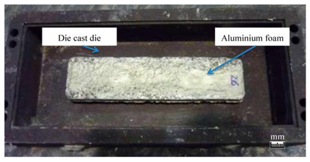
Figure 4. Metallic die to die cast magnesium over the aluminium foam.A preliminary analysis of the die casting, plastic injection, and HPDC processes were employed to determine the effect of pressure over the selected foams, obtianing the samples’ different density ranges. The quality and defects on the quality of the injected parts was determined. This preliminary analysis shows that it was necessary that the aluminium foam has to have a minimum external skin to act as a core without collapsing. Alulight foamed cores supported the magnesium over-injection by HPDC without any damage. Aluminium foams were placed in a Tecnalia’s plastic injection test die at room temperature and after preheating the aluminium foam at 60 °C. A transparent-type plastic TPE (THERMOLAST K TF8CGT, KRAIBURG TPE GmbH & Co, Waldkraiburg, Germany) was over-injected in order to observe the effect of injection parameters over the foam, with an injection pressure of 16–40 MPa, slope temperatures of 180 °C, 200 °C, and 220 °C, die temperature of 40 °C, a flow rate of 45 cm3/s, a cooling time of 40 s, and an injection volume of 46 cm3.After having optimized the injection parameters, the maximum pressure and speed injection parameters for a HPDC process were established. We can observe in Figure 5 the plastic injection mold with aluminium foam placed on the die before the injection of the plastic.
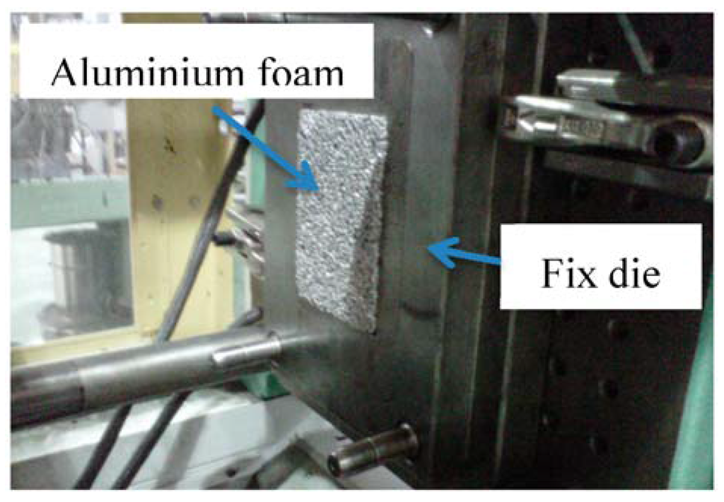
Figure 5. The plastic injection mould with an aluminium foam.To determine the real behavior of aluminium foam cores working with a HPDC process, a series of castings were produced with a 950 ton HPDC machine produced by Pretransa at Tecnalia´s foundry pilot plant. Standard HPDC magnesium injection parameters were used. The pressure ranges used variated from 20 to 80 MPa of specific pressure, 0.25 m/s first phase piston speed, and second phase speed in the range between 20 and 80 m/s. The die used to produce the castings was a multi-cavity die with a bicycle rod and a squeeze pin cavity. We can observe in Figure 6 the process to produce the composite casting with the aluminium foam core and the AM60B magnesium alloy.
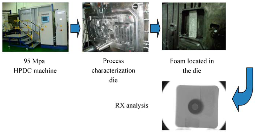
Figure 6. HPDC process in order to obtain the magnesium-aluminium foam core composite.In order to fix the aluminium foam core to the die in the bicycle rod cavity, the die was modified. Four pins of 1 mm diameter and 1 mm height were located in the fix part of the die, as we can observe in Figure 7. The aluminium foam was inserted on the pins, by pressing the foam in the die cavity.
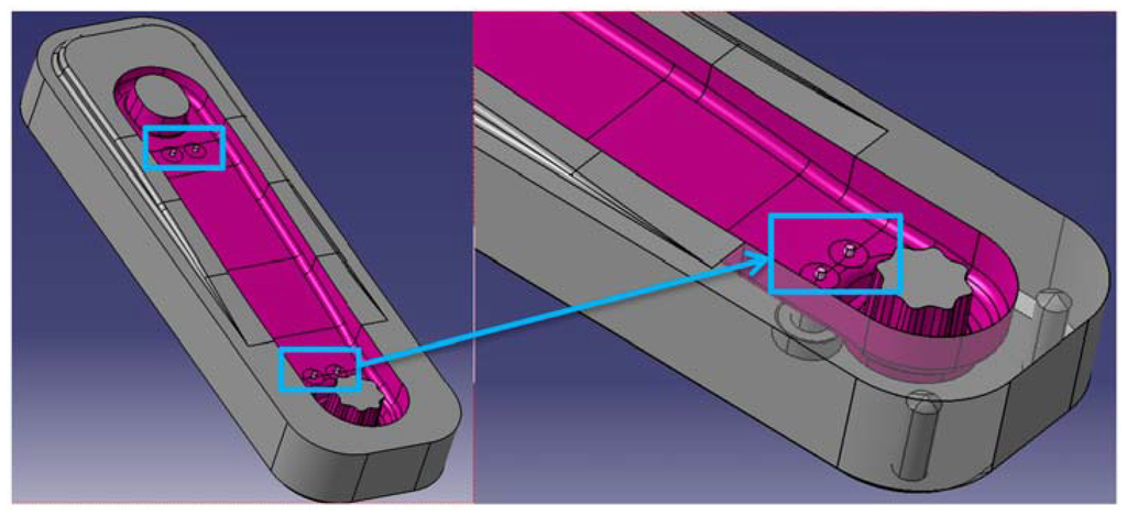
Figure 7. Detail of fixing pins in the fixed die cavity for placing the aluminium foam.The bicycle rod is composed by a central straight body of 210 mm length, 40 mm width, and from 12 to 16 mm thickness, with two cavities in the extremes that are the sockets that connect the rod with the pedal and the shaft. The rods had been submitted to X-ray analysis employing a General Electric X-cube 44XL (GE Sensing & Inspection Technologies GmbH, Ahrensburg, Germany) at 160 kV to confirm the absence of broken cores that could invalidate the results of the tests, to control the soundness of the components, and to identify potential defects.Finally, in order to determine the mechanical properties of the composite rods, three tensile test were carried out in accordance with the UNE-EN ISO 6892-1 B:2010 standards at room temperature with a crosshead speed of 5 mm/min using an Instron 3369 electromechanical testing machine. The tensile stress, ultimate tensile strength, and elongation were calculated from obtained stress-strain diagrams.
3. Results
3.1. Determination of Metal Casting Temperature
Different experiments have been developed in order to determine the accuracy of different types of aluminium foams and casting parameters.The first casting trials were made by casting the AM60B alloy at 680 °C and 720 °C over an aluminium foam core.At 680 °C short fill/cold shut defects were detected as shown in Figure 8a. In Figure 8b we can observe some gas liberation from the aluminium foam.

Figure 8. (a) Short fill and cold shut defects; and (b) gas porosity defects.The three different types of aluminium foams did not show any casting defects (short fill/poor filling) or any damage on the foam when the magnesium alloy was poured at 720 °C, so a minimum pouring temperature of 720 °C was needed to avoid any poor filling defect. However as expected, there was not an interphase between the aluminium foam and the over-casted AM60B alloy.As we can observe in Figure 9 the Alulight-type foam is cover with AM60B magnesium without gas porosity, because the external skin of about 0.5 mm thickness of the Alulight type foam avoids the expansion of the gas bubbles inside the magnesium casting.
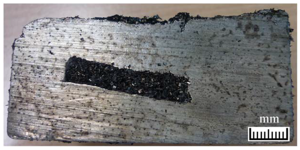
Figure 9. Central aluminium core covered with AM60B.
3.2. Determination of Injection Pressure
In order to simulate only the pressure action of an injected material over different aluminium foams, a transparent plastic was injected over the three types of foams at pressures between 16–40 MPa, with the objective of determining which kind of aluminium foam, density, and combination of different foams is necessary to support the standard 40 MPa specific pressure for magnesium HPDC. We can observe in Figure 10 different configurations and combinations of aluminium foams.
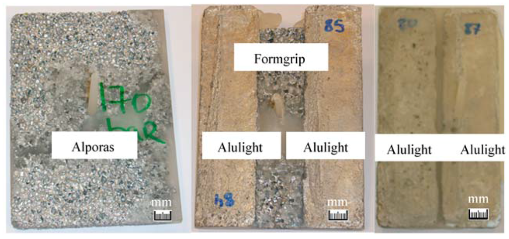
Figure 10. Different configurations for plastic injection over the aluminium foams.In Table 4 we can observe the obtained integrity results for the different types and densities of the foams.Table 4. Integrity of aluminium foams after plastic injection.

Despite the different densities, it is shown that only the Alulight foam resists the standard 40 MPa specific pressure for magnesium HPDC.In order to simulate the industrial application, HPDC trials were carried out. First Alporas and Formgrip foams were over-injected with standard HPDC magnesium injection parameters and with and alloy injecting temperature of 680 °C, in order to confirm the obtained results in the plastic injection machine. In Figure 11a we can observe Alpora’s foams and Formgrip foams in Figure 11b. Both types of foams were destroyed over the standard injection conditions, as shown in Figure 12, so they were discarded from being employed in HPDC.

Figure 11. (a) Alpora’s foam (0.25 to 0.4 Kg/dm3); and (b) Formgrip’s foam (0.4 to 0.65 Kg/dm3).
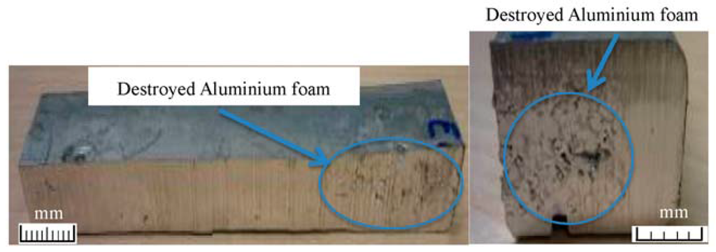
Figure 12. HPDC part with totally destroyed aluminium foam.In order to determine the possibility of employing foams with non-skinned areas, Alulight aluminium foam samples cut at their center were introduced in the squeeze pin cavity of the HPDC die and over-injected with the magnesium alloy at 680 °C. We can observe in Figure 13a how the sample is introduced in the die and in Figure 13b how the non-skinned area promoted the formation of gas porosity inside the cast part.
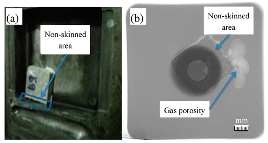
Figure 13. (a) Placement of a skinned foam with a non-skin area in the die; and (b) release of gas from the foam in the non-skinned area.As we have observed above, open skin foams can liberate the foaming gas in contact with molten magnesium, promoting gas porosity inside the cast part. Thus, foams which contain areas without an external skin cannot work properly as cores in the HPDC process.
3.3. Determination of Squeeze Pin Suitability for Composite Cast Parts
In order to study the possibility of employing up to 200 MPa of specific pressure in specific areas using an squeeze pin with composite components for reducing shrinkage porosity, several aluminium foam cores with densities from 0.6 to 1.55 Kg/dm3 were placed into the squeeze pin cavity, and the action of the squeeze pin pressure was evaluated on the foam integrity, with the same casting parameters employed in previous tests. We can observe in Figure 14 how the pressure acts over the foam core.
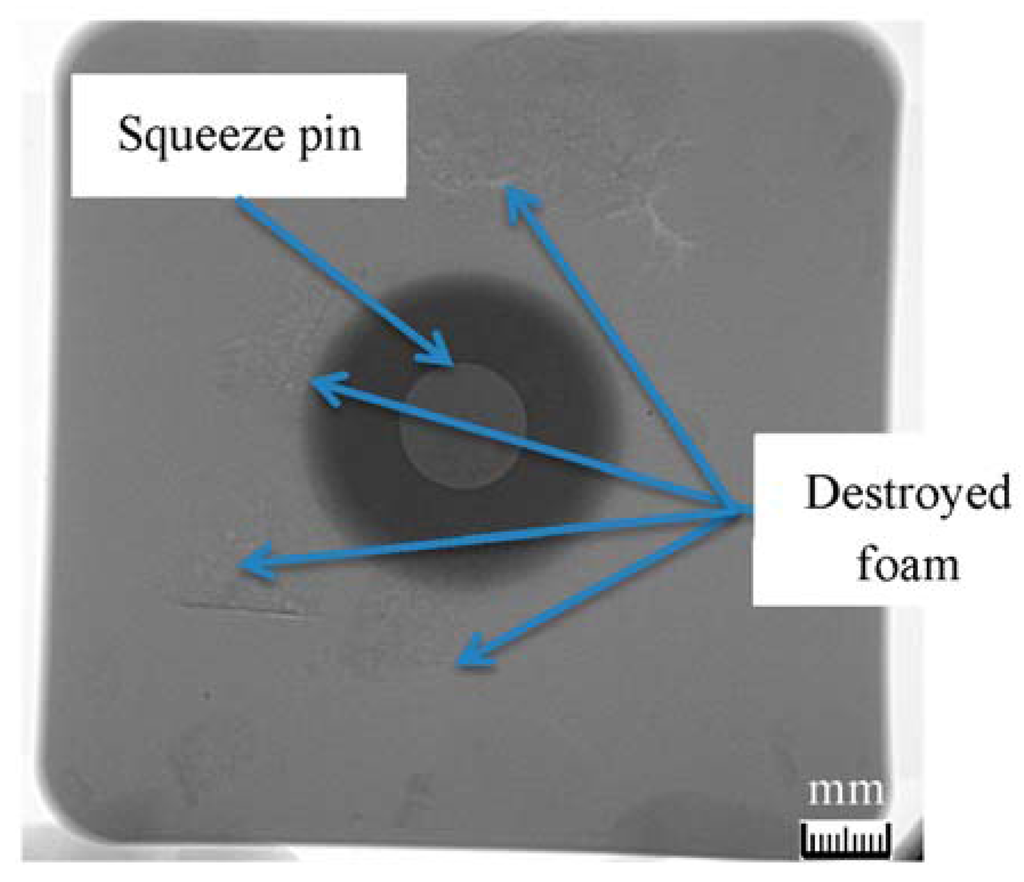
Figure 14. 1.55 Kg/dm3 Aluminium foam after squeeze pin application.As we can notice, the foam is totally destroyed in small pieces. Thus, the squeeze pin application in areas near the aluminium foam is not possible, despite increasing foam density.
3.4. Determination of Core Placement
The position of the foam core has been also studied in order to determine if it can be employed in any position or if the high injection speeds and pressures can damage it as a function of the position of the foam in the die with respect to the metal flow into the cavity. Two different configurations were tested. We can observe in Figure 15 the behavior of a core placed horizontally to the flow .
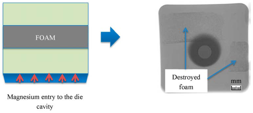
Figure 15. Horizontal placement to the metal flow of the core.The impact of the metal flow with the foam core causes a shear rupture of the core foam. It is necessary to select the positioning of the core in the die or the metal flows over the core by re-designing the runners in order to decrease the direct impact of injected metal on the core.We can observe in Figure 16 how a core placed vertically to the flow with the rod demonstrator does not present any damage on the aluminium foam, with only small shrinkage porosity areas.
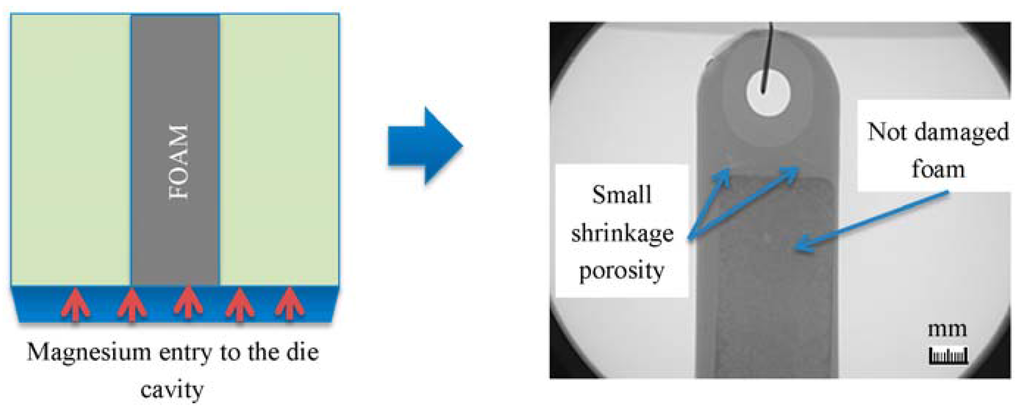
Figure 16. Horizontal core placement to metal flow.An optimal placement of the foam is critical to avoid damages in the aluminium foam and to obtain sound parts. In Figure 17 we can observe a complete magnesium rod without any external quality defect, with the internal aluminium foam core.

Figure 17. Rod made by magnesium HPDC with the internal core of aluminium foam.
3.5. Determination of Injection Speed
Another critical HPDC parameter is the injection speed. The metal speed in the gates was varied from 20 to 80 m/s and the specific injection pressure over the cast part from 20 to 80 MPa, with the aluminium foam and an alloy temperature of 680 °C. We can observe in Figure 18 how, if we reduce the first injection speed, the part quality is adversely affected.
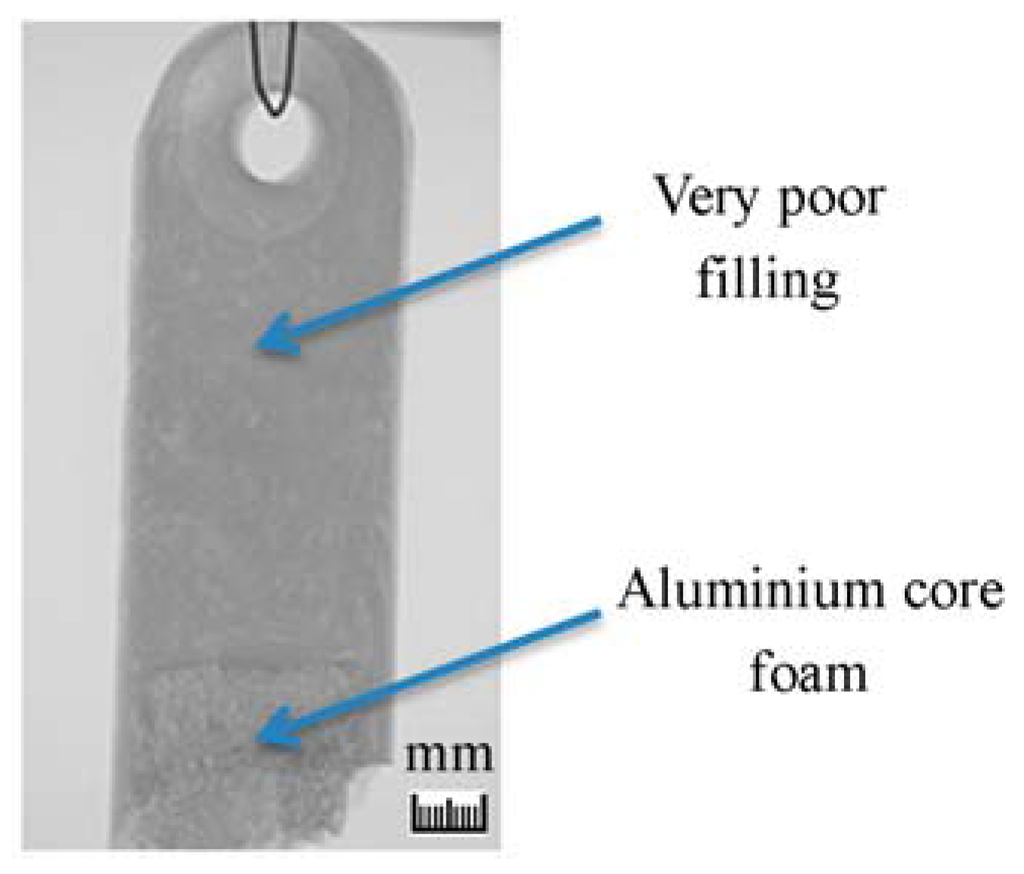
Figure 18. Reduced second phase speed (20 m/s) HPDC cast part.With magnesium HPDC standard parameters, establishing the second injection speed at 80 m/s and the specific injection pressure at 80 MPa, sound parts were obtained. Only some small solidification porosity was detected. We can observe in Figure 19 an example of the quality obtained on the final composite cast part.
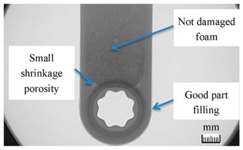
Figure 19. Injected HPDC with core foam at standard parameters.In the case of employing the Alulight-type aluminium foam of 0.56 Kg/dm3 density, a total weight reduction is of about a 35% is obtained.
3.6. Determination of Mechanical Properties
In order to determine the mechanical properties, tensile tests were made over three AM60B alloy injected rods, and compared with three aluminium foam-magnesium composite injected rods. The percentage of aluminium foam area in comparison with the total area in the central region of the injected part is about 47%. We can observe the obtained results in Table 5, with an extrapolation of obtained properties of composite rods in relation with the reduction of weight obtained with the use of aluminium foam cores:Table 5. Obtained properties of composite rods.

4. Discussion
The absence of an external minimum and continuous skin on the aluminium foams promotes the presence of internal gas porosity in the composite cast part, due to the gas liberation in the injection process from the surface of the foam. This liberation is promoted by the presence of small cracks in some of the external pores forced by the metal injection speed and pressure.The absence of an external continuous skin on the foam surface decreases the mechanical resistance to the injection speed and pressure, destroying the foam. The presence of a continuous skin of about 1 mm gives the necessary robustness to the foam to support the injection process. The higher the density, the better the mechanical resistance of the foam, but only when there is a continuous skin because, despite increasing the density of foams, they are collapsed by the injection conditions. However, the increase in tensile test values over Alulight-type foams is very limited [35].Positioning the aluminium foam opposite to the entry of the metal in the cavity results in a resistance to the free entry of the molten metal into the die cavity, and shear fractures of the aluminium foams due to the combination of high speeds and pressures are produced.The use of squeeze pins on areas to reduce shrinkage porosity on areas closer to aluminium foams should be avoided because the extremely high pressures (up to 200 MPa) employed by the squeeze pins cannot be supported by the foams. With specific pressures up to 800 MPa in the injection trials the aluminium foam cores supported the applied pressure without any damage, well above the standard magnesium HPDC specific pressures employed in the industry.There is not a chemical bonding between the aluminium foam core and the over-casted magnesium alloy, because the aluminium foam is totally covered with an alumina surface that prevents the direct contact between the aluminium of the foam and the molten magnesium. This lack of a chemical bonding decreases the final mechanical properties of the composite, reducing the mechanical properties to these related to the cast magnesium. The increase in the obtained mechanical values in the composite cast part in comparison with the correlated magnesium cast part mechanical values could be related to the internal presence of the aluminium foam, with its intrinsic mechanical properties, and by the higher cooling rate on the surface in contact with the molten magnesium, creating an internal surface in the magnesium with an smaller grain size in comparison with a solidification without a core.The next work will focus on studying the application of surface treatments over the aluminium foam for obtaining a continuous interphase between the aluminium foam and the cast magnesium. This could increase the bond strength between the two materials, increasing the mechanical interlocking. By studying, for example, Zn-based coatings for the aluminium foams it is estimated that the ultimate tensile strength could be slightly improved (approx. 3–5 Mpa).
5. Conclusions
HPDC magnesium aluminium foam composite has been developed for applications requiring a reduction on part weight. Optimum aluminium core foam produced by the Alulight process has been defined through an experimental approach.The Alulight process permits obtaining close pore foams with an external skin that avoids the presence of internal defects in the composite. Densities may have changes for the core foam from 0.54 to 1.55 Kg/dm3. The regulation of the foam porosity allows tailoring properties and customizing the part for specific performances, but in applications where the main objective is weight reduction, foams of only 0.54 kg/dm3 overcame casting conditions. The estimated cost on material and production by using an aluminium foam in the bicycle rod is of about 0.3 Euros/part, which is a reasonable cost.The developed composite casting has been used for the production of a bicycle rod. Tensile tests have subsequently confirmed the validity of the composite casting for this application and its actual potential to substitute currently used aluminium, titanium, or carbon fiber materials. A reduction of 35% in the total weight of the part has been obtained. Higher reductions are possible depending on the part. Magnesium HPDC can be a solution for mass production of composites with foams, as an alternative to plastics and aluminium parts.The use of aluminium foams does not seem to give higher mechanical properties to composite cast parts. The tensile test shows very similar values to calculated ones when a hollow area in the middle of the rod is used for estimations. However, the process permits to reduction in the weight of cast parts where the core area has only relative influence over the final mechanical properties. It would be also possible to obtain improvements on vibration/sound control, crash performance, or compression properties in other applications or final parts.
Acknowledgments
This work has been partially funded by the Spanish government through the project CDTI: MAGNO CENIT project CEN-20081028. The authors are also much grateful to the personnel of Grupo Antolín, company that collaborated in aspects related to the development and analysis of the rod and to Industrias Lebario, who collaborated in the development of aluminium foam dies.
Author Contributions
I.V. and I.C. performed the experiments; I.V., L.M.P. and P.C. analyzed the data; I.V. and P.C. wrote the paper; J.K.I. supervised the work.
Conflicts of Interest
The authors declare no conflict of interest.
References
- Schultz, R. Aluminium Association Auto and Light Truck Group 2009 Update on North American Light Vehicle Aluminium Content Compared to the other Countries and Regions of the World. Phase II; Ducker Worlwide LLC: Troy, MI, USA, 2008; pp. 8–19. [Google Scholar]
- Bonollo, F.; Urban, J.; Bonatto, B.; Botter, M. Gravity and low pressure die casting of aluminium alloys: A technical and economical benchmark. Metall. Ital. 2005, 97, 23–32. [Google Scholar]
- Luo, A.A. Magnesium casting technology for structural applications. J. Magnes. Alloys 2013, 1, 2–22. [Google Scholar] [CrossRef]
- Gertsberg, G.; Nagar, N.; Lautzker, M.; Bronfin, B. Effect of HPDC parameters on the performance of creep resistant alloys MRI153M and MRI230D. SAE Tech. Pap. 2005, 1, 1–7. [Google Scholar]
- Otarawanna, S.; Laukli, H.I.; Gourlay, C.M.; Dahle, A.K. Feeding mechanisms in high-pressure die castings. Metall. Mater. Trans. A 2010, 41, 1836–1846. [Google Scholar] [CrossRef]
- Bonollo, F.; Gramegna, N.; Timelli, G. High-pressure die-casting: Contradictions and challenges. JOM 2015, 67, 901–908. [Google Scholar] [CrossRef]
- Yim, C.D.; Shin, K.S. Semi-solid processing of magnesium alloys. Mater. Trans. 2003, 44, 558–561. [Google Scholar] [CrossRef]
- Sabau, A.S.; Dinwiddie, R.B. Characterization of spray lubricants for the high pressure die casting processes. J. Mater. Process. Technol. 2008, 195, 267–274. [Google Scholar] [CrossRef]
- Kimura, R.; Yoshida, M.; Sasaki, G.; Pan, J.; Fukunaga, H. Characterization of heat insulating and lubricating ability of powder lubricants for clean and high quality die casting. J. Mater. Process. Technol. 2002, 130–131, 289–293. [Google Scholar] [CrossRef]
- Puschmann, F.; Specht, E. Transient measurement of heat transfer in metal quenching with atomized sprays. Exp. Therm. Fluid Sci. 2004, 28, 607–615. [Google Scholar] [CrossRef]
- Rogers, K.J.; Savage, G. In-cavity pressure sensors-errors, robustness and some process insights. Die Cast Eng. 2000, 44, 76–80. [Google Scholar]
- Kong, L.X.; She, F.H.; Gao, W.M.; Nahavandi, S.; Hodgson, P.D. Integrated optimization system for high pressure die casting processes. J. Mater. Process. Technol. 2008, 201, 629–634. [Google Scholar] [CrossRef]
- Keber, K.; Bormann, D.; Möhwald, K.; Hollander, U.; Bach, W. Compound casting of aluminium and magnesium alloys by High Pressure Die Casting. In Proceedings of the Magnesium 8th International Conference on Magnesium Alloys and Their Applications, Weimar, Germany, 26–29 October 2009; pp. 390–397.
- Kunst, M.; Fischersworring-bunk, A.; Liebscher, C.; Glatzel, U.; Esperance, G.L.; Plamondon, P.; Baril, E.; Labelle, P. Microstructural characterization of Die Cast Mg-Al-Sr (AJ) Alloy. In Proceedings of the Magnesium: Proceedings of the 7th International Conference on Magnesium Alloys and Their Applications, Dresden, Germany, 6–9 November 2006; pp. 498–505.
- Vicario, I. Study of high pressure die cast AZ91D magnesium alloy with surface treated aluminium 6063 cores for Al-Mg multi-material. In Proceedings of the 2nd Annual World Congress of Advanced Materials, Suzhou, China, 5–7 June 2013; pp. 7–21.
- Yaokawa, J.; Miura, D.; Anzai1, K.; Yamada, Y.; Yoshii, H. Strength of salt core composed of alkali carbonate and alkali chloride mixtures made by casting technique. Mater. Trans. 2007, 5, 1034–1041. [Google Scholar] [CrossRef]
- Moschini, R. Production of Hollow Components in HPDC through the Use of Ceramic Lost Cores; XXXI Congreso Tecnico di Fonderia: Vincenza, Italy, 2012; pp. 1–33. [Google Scholar]
- Yamada, Y.; Yaokawa, J.; Yoshii, H.; Anzai, K.; Noda, Y.; Fujiwara, A.; Suzuki, T.; Fukui, H. Developments and application of expendable salt core materials for high pressure die casting to apply closed-deck type cylinder block. SAE Int. 2007, 32-0084, 1–5. [Google Scholar]
- Vicario, I.; Egizabal, P.; Galarraga, H.; Plaza, L.M.; Crespo, I. Study of an Al-Si-Cu HPDC alloy with high Zn content for the production of components requiring high ductility and tensile properties. Int. J. Mater. Res. 2013, 4, 392–397. [Google Scholar] [CrossRef]
- Benedick, C. Production and application of aluminium foam, past product potential revisited in the new millennium. Light Met. Age 2002, 60, 24–29. [Google Scholar]
- Bausmesiter, J.; Weise, J. Structural Materials and Processes in Transportation, Metal Foams; John Wiley & Sons: Hoboken, NJ, USA, 2013; pp. 415–440. [Google Scholar]
- Banhar, J. Metal foams: Production and stability. Adv. Eng. Mater. 2006, 9, 781–794. [Google Scholar] [CrossRef]
- Coleto, J.; Goñi, J.; Maudes, J.; Leizaola, I. Applications and manufacture of open and closed cell metal foams by foundry routes. In Proceedings of International Congress Eurofond, La Rochelle, France, 2–4 June 2004; pp. 1–10.
- Körner, C.; Hirschmann, M.; Wiehler, H. Integral Foam Moulding of Light Metals. Mater. Trans. 2006, 47, 2188–2194. [Google Scholar] [CrossRef]
- Baumeister, J.; Weise, J. Application of aluminium-polymer hybrid foam sandwiches in battery housings for electric vehicles. Procedia Mater. Sci. 2014, 4, 301–330. [Google Scholar] [CrossRef]
- Vesenjak, M.; Borovinšek, M.; Fiedler, T.; Higa, Y.; Ren, Z. Structural characterisation of advanced pore morphology (APM) foam elements. Mater. Lett. 2013, 110, 201–203. [Google Scholar] [CrossRef]
- Miyoshi, T.; Itoh, M.; Akiyama, S.; Kitahara, A. Aluminium foam, “ALPORAS”: The production process, properties and application. In Materials Research Society Symposium Proceedings, Boston, MA, USA, 1–3 December 1998; 1998; pp. 133–137. [Google Scholar]
- Miyoshi, T.; Itoh, M.; Akiyama, S.; Kitahara, A. Alporas aluminum foam: Production process, properties, and applications. Adv. Eng. Mater. 2000, 2, 179–183. [Google Scholar] [CrossRef]
- Gegerly, V.; Clyne, T.W. The formgrip process: Foaming of reinforced metals by gas release in precursors. Adv. Eng. Mater. 2002, 2, 175–178. [Google Scholar]
- Gergely, V.; Curran, D.C.; Clyne, T.W. Advances in the melt route production of closed cell aluminium foams using gas-generating agents. In Proceedings of Global Symposium of Materials Processing and Manufacturing Processing & Properties of Lightweight Cellular Metals and Structures, Seattle, WA, USA, 17–21 February 2002; pp. 3–8.
- Baumeister, J. Production technology for aluminium foam/steel sandwiches. In Proceedings of the International Conference on Metal Foams and Porous Metal Structures, Bremen, Germany, 14–16 June 1999; pp. 113–118.
- Seeliger, H.W. Cellular Metals: Manufacture, properties, applications. In Proceedings of the MetFoam, Berlin, Germany, 23–25 June 2003; pp. 5–12.
- Kováãik, J.; Simančík, F.; Jerz, J.; Tobolka, P. Reinforced aluminium foams. In Proceedings of the International Conference on Advanced Metallic Materials, Smolenice, Slovakia, 5–7 November 2003; pp. 154–159.
- Braune, R.; Otto, A. Tailored blanks based on foamable aluminium sandwich material. In Proceedings of the International Conference on Metal Foams and Porous Metal Structures, Bremen, Germany, 14–16 June 1999; pp. 119–124.
- Gutiérrez-Vázquez, J.A.; Oñoro, J. Fabricación y comportamiento de espumas de aluminio con diferente densidad a partir de un precursor AlSi12. Rev. Metal. 2010, 46, 274–284. [Google Scholar] [CrossRef][Green Version]
© 2016 by the authors; licensee MDPI, Basel, Switzerland. This article is an open access article distributed under the terms and conditions of the Creative Commons by Attribution (CC-BY) license (http://creativecommons.org/licenses/by/4.0/).