Beyond Conventional Casting: A Deep Dive into Semi-Solid Metal (SSM) Processing for Superior Alloy Components
This technical summary is based on the academic book "Semi-solid Processing of Alloys" by David H. Kirkwood, Michel Suéry, Plato Kapranos, Helen V. Atkinson, and Kenneth P. Young, published by Springer in 2010.

Keywords
- Primary Keyword: Semi-Solid Metal Processing (SSM)
- Secondary Keywords: Thixoforming, Rheocasting, High Pressure Die Casting (HPDC), Alloy Processing, Microstructure Control, Casting Defects
Executive Summary
- The Challenge: The high cost and process limitations of traditional thixoforming have historically hindered the wider adoption of Semi-Solid Metal Processing's benefits in producing high-integrity components.
- The Method: The development and industrialization of new on-site slurry generation techniques, collectively known as rheocasting, which start from standard liquid metal.
- The Key Breakthrough: Modern rheocasting eliminates the need for expensive, specially-made billets and allows for in-house scrap recycling, directly addressing the main cost and logistical barriers of older SSM methods.
- The Bottom Line: Advanced rheocasting processes are making SSM an economically viable and superior alternative to conventional HPDC for manufacturing heat-treatable, high-performance alloy components.
The Challenge: Why This Research Matters for HPDC Professionals
For decades, engineers have recognized the potential of Semi-Solid Metal (SSM) processing. The technology promises the best of both casting and forging: the ability to create complex, near net-shape parts with a superior internal structure, free from the turbulence and gas porosity that plague traditional liquid-metal die casting. This results in fully heat-treatable components with excellent mechanical properties and surface finish.
However, the dominant SSM method, thixoforming, has faced significant commercial headwinds. The process relies on reheating specially manufactured feedstock billets with a non-dendritic microstructure, typically produced via costly Magneto-Hydrodynamic (MHD) stirring. This premium on raw materials, combined with the inability for manufacturers to recycle their own scrap in-house, has confined SSM to niche, high-value applications. The core challenge has been clear: how to unlock the quality benefits of SSM without the prohibitive cost and supply chain complexity?
The Approach: Unpacking the Methodology
The book details the evolution of SSM technology, focusing on the fundamental shift from billet-based methods to direct slurry-based methods.
Method 1: Thixoforming (The Traditional Route)
This process begins with a solid, specially-cast billet that already possesses the required globular (non-dendritic) internal microstructure. This billet is cut into slugs, reheated into the semi-solid range (typically 50-60% solid), and then injected into a die. While it produces high-quality parts, its reliance on premium-cost feedstock has been its primary limitation.
Method 2: Rheocasting (The Modern Solution)
This is the original concept of SSM, now seeing a major resurgence thanks to new technology. Rheocasting creates the semi-solid slurry directly from standard liquid metal at the casting cell, just before injection. This eliminates the entire billet-manufacturing and reheating supply chain. The book highlights several innovative approaches:
* New Rheo-Casting (NRC) Process: Uses controlled cooling of liquid metal in a cup to form a globular structure without mechanical stirring.
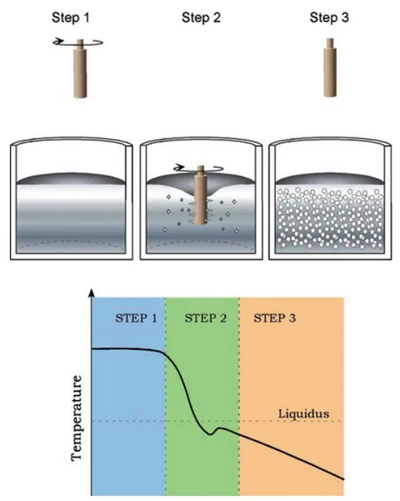
* Semi-Solid Rheocasting (SSR™) Process: Introduces a spinning "cold finger" into the molten alloy. This rapidly extracts heat and provides mechanical agitation, creating a large number of fine, equiaxed dendrites that quickly coarsen into the desired globular particles. The resulting low-viscosity slurry can be handled at lower solid fractions (<30%) and poured directly into a standard die casting machine's shot sleeve.
The Breakthrough: Key Findings & Data
The comprehensive analysis reveals two game-changing breakthroughs that are making modern rheocasting a viable mainstream process.
Finding 1: Drastic Cost Reduction via On-Site Slurry Generation
The primary advantage of modern rheocasting routes is economic. By starting with standard, commodity-grade liquid alloy, these processes completely eliminate the need for premium-cost MHD-stirred billets. As detailed in Chapter 10, this approach not only reduces raw material costs but also solves a critical operational problem: scrap recycling. Runners, biscuits, and rejected parts can be remelted directly on-site, closing the loop and dramatically improving material utilization. This circumvents the financial penalty of having to send scrap back to a specialized billet producer.
Finding 2: Superior Flow Dynamics for Defect-Free, Heat-Treatable Parts
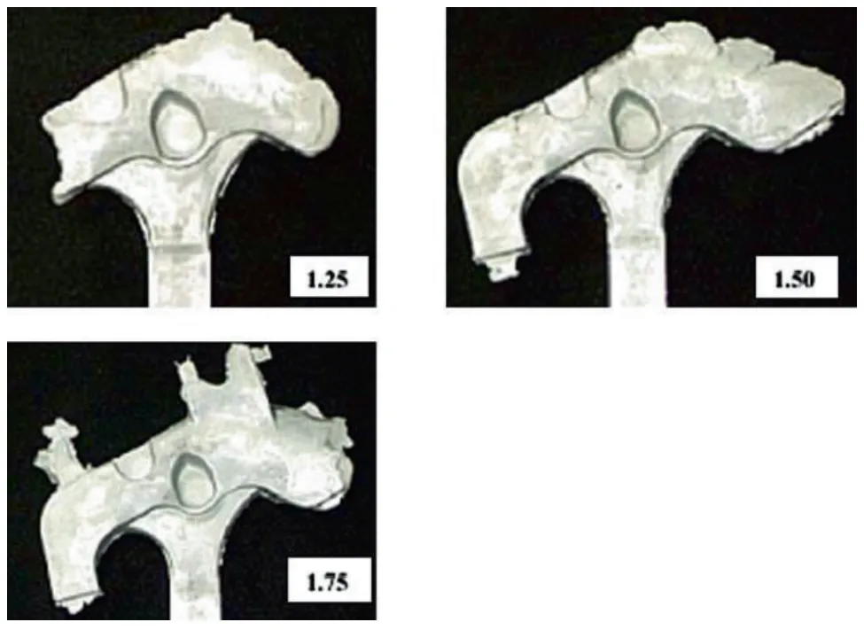
The high apparent viscosity of semi-solid slurry fundamentally changes how it fills a die. Unlike turbulent liquid metal, SSM flows as a smooth, planar front. Figure 11.3 shows interrupted "fill-test" shots, which provide a clear snapshot of this behavior. The material advances evenly from the gate, pushing air ahead of it and preventing the gas entrapment that causes blistering during T6 heat treatment. This predictable, non-turbulent fill is a characteristic of the material itself, not just the machine controls. This enables the production of fully dense, pressure-tight, and heat-treatable structural components, a feat that is extremely difficult with conventional HPDC.
Practical Implications for R&D and Operations
- For Process Engineers: This study suggests that adopting a rheocasting process like SSR can be integrated into existing die casting cells. It allows for the use of standard alloys and offers a new lever—controlled cooling and agitation—to achieve superior part quality and potentially higher productivity through reduced cycle times.
- For Quality Control Teams: The data in the Appendix (Tables 1 & 2) illustrates the superior mechanical properties (fatigue strength, ductility) achievable with thixoformed alloys like A356/A357 compared to conventional castings. The planar flow behavior inherent to SSM directly reduces the porosity and oxide inclusions that are primary targets for quality inspection.
- For Design Engineers: The findings indicate that SSM processing enables the creation of complex, thin-walled (down to 2 mm) structural parts that are fully heat-treatable. This opens the door for lightweighting and part consolidation, replacing multi-piece assemblies or machined components with a single, high-integrity cast part.
Paper Details
Semi-solid Processing of Alloys
1. Overview:
- Title: Semi-solid Processing of Alloys
- Author: David H. Kirkwood, Michel Suéry, Plato Kapranos, Helen V. Atkinson, Kenneth P. Young
- Year of publication: 2010
- Journal/academic society of publication: Springer Series in Materials Science, Volume 124
- Keywords: Semi-solid processing, Rheocasting, Thixoforming, Thixotropy, Microstructure, Rheology, Alloys, Aluminum, Magnesium
2. Abstract:
This monograph provides a comprehensive account of the science and technology of semi-solid metal (SSM) processing. Originating from research at MIT in 1972 on the viscosity of solidifying alloys, SSM is founded on the discovery that shearing a metallic alloy during solidification transforms its dendritic microstructure into a globular one. This change results in a dramatic drop in viscosity, a phenomenon known as thixotropy, enabling the alloy to be processed like a fluid at high solid fractions. The text is structured into three parts. Part I addresses the fundamental aspects of microstructure evolution and design, including nucleation, fragmentation, coarsening, and recent developments in slurry formation. Part II is dedicated to the rheology and modeling of semi-solid alloys, covering experimental methods for determining rheological behavior and the development of computational models for process simulation. Part III focuses on the industrial applications of SSM, detailing raw material production, process control, die design, current practical uses for aluminum and magnesium alloys, and future prospects for high-melting-point alloys. The work synthesizes over three decades of research and industrial practice, examining both the thixoforming and the resurgent rheocasting process routes.
3. Introduction:
The field of semi-solid processing originates from the 1972 discovery by Spencer, Mehrabian, and Flemings at MIT that shearing tin-lead alloys during solidification fundamentally altered the microstructure from a rigid, dendritic network to a slurry of spheroidal solid particles in a liquid matrix. This structural change induced thixotropic behavior, wherein the material's viscosity decreased dramatically under shear, allowing it to be injected into molds. This finding initiated extensive research into two primary process routes: "rheocasting," where the slurry is formed and injected directly, and "thixoforming," where a billet with the desired microstructure is first cast, solidified, and later reheated to the semi-solid state for forming. For many years, thixoforming, particularly using electromagnetically stirred billets, became the dominant industrial method for producing high-integrity components in aluminum and magnesium alloys. However, the high cost of this precursor material and the inability to recycle scrap in-house have limited its widespread application. Consequently, recent developments have led to a resurgence of rheocasting technologies that allow for on-site slurry generation, promising significant cost savings and broader industrial adoption. This monograph aims to provide a balanced and up-to-date account of the fundamental science, rheological behavior, process modeling, and industrial practice of semi-solid processing.
4. Summary of the study:
Background of the research topic:
The research is grounded in the field of physical metallurgy and materials processing, specifically focusing on the behavior of metallic alloys in the semi-solid state (coexistence of solid and liquid phases). The key phenomenon is thixotropy, previously known in ceramics and polymers but first observed in metallic systems in 1972. This behavior forms the basis for a hybrid metal forming technology that combines features of casting and forging.
Status of previous research:
The book builds upon approximately 37 years of academic and industrial research since the initial discovery at MIT. Previous work established the two main process routes (rheocasting and thixoforming), characterized the shear-thinning and time-dependent rheology of various alloys, and led to the commercial production of components, primarily for the automotive and electronics industries. Much of the industrial focus had been on thixoforming of aluminum alloys using feedstock produced by magneto-hydrodynamic (MHD) stirring.
Purpose of the study:
The purpose of this monograph is to consolidate the extensive body of research on semi-solid processing into a single, comprehensive volume. It aims to detail the process fundamentals, from microstructure evolution to rheological modeling, and to describe the practical industrial applications, process control strategies, and future directions of the technology. It addresses both the established thixoforming route and the newly developing rheocasting technologies designed to overcome previous economic barriers.
Core study:
The book is a comprehensive review structured in three distinct parts:
1. Evolution and Design of Microstructure in Semisolid Alloys: This section covers the fundamental metallurgical principles governing the formation of the required globular microstructure, including nucleation, grain multiplication, coarsening, and characterization. It also details recent technological advancements in slurry formation.
2. Rheology and Modeling: This part examines the complex flow behavior of semi-solid slurries. It describes experimental techniques for determining rheological properties like viscosity and yield stress and discusses the development of continuum models (both one-phase and two-phase) using finite difference and finite element methods to simulate die filling and predict defects.
3. Industrial Applications of Semisolid Processing: This section bridges theory and practice, covering the production of raw materials, process control in die filling, component and die design rules, and a survey of practical applications in use today. It concludes with an outlook on the future of the technology, including the processing of high-temperature alloys like steel.
5. Research Methodology
Research Design:
As a scientific monograph and review, the research design is a comprehensive synthesis of existing knowledge. The authors have structured the book to logically progress from fundamental scientific principles to applied industrial technology. The work collates, analyzes, and interprets decades of research papers, conference proceedings, patents, and industrial case studies.
Data Collection and Analysis Methods:
The methodology involves a thorough literature review across three core areas:
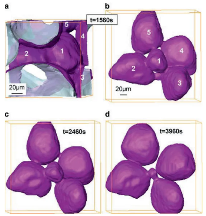
1. Metallurgical Analysis: Review of experimental studies on microstructure evolution using techniques such as optical metallography, serial sectioning, and advanced methods like in-situ X-ray microtomography to understand spheroidization and coarsening kinetics.
2. Rheological Characterization: Synthesis of data from various experimental apparatuses, including Couette and parallel-plate viscometers, capillary rheometers, and compression tests, used to measure the viscosity, thixotropy, and yield stress of semi-solid slurries under different conditions of shear rate, temperature, and time.
3. Process Simulation and Industrial Practice: Analysis of computational modeling studies (CFD, FEM) used to predict material flow and defect formation, alongside a review of industrial implementations, process control strategies, and component performance data from commercial producers.
Research Topics and Scope:
The scope of the book is broad, covering the entire field of semi-solid processing for metallic alloys. The primary focus is on aluminum and magnesium alloys, which constitute the bulk of industrial applications. The topics range from the atomic level (interface structure) to the macroscopic (industrial machine design and component performance). The research encompasses theoretical fundamentals, experimental characterization, numerical modeling, and real-world industrial applications and economics.
6. Key Results:
Key Results:
- The fundamental advantage of SSM processing stems from the transformation of a dendritic solid-liquid microstructure into a globular one through the application of shear, resulting in thixotropic behavior and a significant reduction in viscosity.
- The evolution of the microstructure during isothermal holding involves two primary processes: rapid initial spheroidization (driven by reduction of local interface curvature) and slower subsequent coarsening/ripening (Ostwald ripening and particle coalescence).
- Semi-solid slurries exhibit complex, non-Newtonian, shear-thinning, and time-dependent (thixotropic) rheological behavior. Viscosity is a strong exponential function of solid fraction.
- Computational modeling, particularly using CFD with thixotropic fluid models, is a critical tool for optimizing die design and process parameters, capable of predicting and mitigating defects such as turbulent filling, jetting, and liquid segregation.
- The primary historical barrier to widespread SSM adoption has been the high cost of specialized precursor billets (thixoforming). New rheocasting technologies that generate slurry on-site from standard ingot are emerging as a cost-effective solution, enabling in-house scrap recycling and making the technology economically competitive with conventional casting processes.
- SSM processing produces high-integrity, low-porosity components capable of being heat-treated to achieve superior mechanical properties (e.g., fatigue strength) compared to conventional die castings.
Figure Name List:
- Fig. 1.1 Simple Binary Alloy Equilibrium Diagram
- Fig. 1.2 The effect of Cooling Rate on the fraction of Primary Solid formed
- Fig. 1.3 Free energy of growing embryo/nucleus
- Fig. 1.4 Homogeneous and heterogeneous nucleation rates as a function of undercooling
- Fig. 1.5 Cap of solid phase forming from the liquid on an impurity surface by heterogeneous nucleation
- Fig. 1.6 The bold line indicates the undercooling necessary for grain initiation. The free-growth undercooling is calculated; the nucleation undercooling is schematic only. Inset (1) shows the classical spherical-cap model for heterogeneous nucleation. Inset (2) shows a cap of ˛–Al growing on an inoculant particle through the critical hemispherical condition [5]
- Fig. 1.7 The number of grains per unit volume as a function of the number of refiner particles per unit volume, showing a general trend to lower efficiency at higher addition level. Data from grain diameters measured in TP-1 tests (closed circles) are compared with predictions of the free-growth model (open circles) [5]. The predictions are qualitatively different from those of Maxwell and Hellawell [6] and are a much better fit to the data [5]
- Fig. 1.8 Distribution of (a) solute and (b) temperature ahead of a moving planar interface showing the development of Constitutional Undercooling.
- Fig. 2.1 Schematic representation of complex Dendrite Structure, (a) 3D view (b) Cross Section.
- Fig. 2.2
- Fig. 3.1 (a, c, e) Conventional casting after 0 min, 5 min, and 15 h soaking, (b, d, f) MHD casting after 0 min, 5 min, and 15 h soaking
- Fig. 3.2 Microstructural changes in DC cast Al/7%Si Alloys during isothermal heat treatment at 580 degC.
- Fig. 3.3 Effect of Cold Work on particle spheroidisation (closed circles) compared to undeformed alloy (open circles).
- Fig. 3.4 Observations of neck representative of trend with unequal sized particles
- Fig. 3.5 Observations of neck representative of trend for equal sized particles
- Fig. 3.6 Variation of the average solid particle volume and equivalent radius with isothermal holding time
- Fig. 4.1 Schematic of the SSR process
- Fig. 4.2 Schematic of dendrite multiplication
- Fig. 4.3 Micrograph of Al–Cu alloy rheocast with SSR and then immediately quenched. Spheroidal primary grains are evident that formed during the initial period of solidification with subsequent dendritic microstructure that formed during the quench
- Fig. 4.4 Microstructures of reheated and quenched Al–Si alloy produced by (a) SSR and (b) electromagnetically stirred MHD continuous cast billet [35]
- Fig. 6.1 Devices used to measure the fluidity. (a) spiral; (b) vacuum suction
- Fig. 6.2 Apparent viscosity as a function of the solid fraction for an A356 alloy sheared at (filled square) 27 s−1, (open square) 54 s−1, (filled circle) 108 s−1, and (open circle) 216 s−1 during continuous cooling in the solidification interval at 1.2◦C min−1 (from [11])
- Fig. 6.3 Apparent viscosity as a function of shearing time at 590◦C of a A356 alloy (fs = 0.35) partially solidified with a shear rate of (filled square) 27 s−1, (open square) 54 s−1, (filled circle) 108 s−1, and (open circle) 216 s−1 (from [11])
- Fig. 6.4 Apparent viscosity as a function of shearing time at a shear rate of 200 s−1 and at various temperatures corresponding to solid fraction fs = 0.3 (open square), 0.4 (filled circle), and 0.5 (filled square). Al-4.5%Cu-1.5%Mg (from [12])
- Fig. 6.5 Apparent viscosity of an A356 alloy as a function of the shear rate for various solid fractions (from [3])
- Fig. 6.6 Variation of the apparent viscosity at steady state as a function of the volume fraction of solid increased by the liquid volume fraction entrapped in the agglomerates for various shear rates (from [15])
- Fig. 6.7 Effect of the resting time tr on the hysteresis loops of a Sn-15%Pb alloy; tu is the time required to increase the shear rate up to its maximum value (from [2])
- Fig. 6.8 Shear rate jumps from 0 to 100 s−1 after different rest times for Sn-15%Pb alloy at fraction solid 0.36 [23]
- Fig. 6.9 Apparent viscosity as a function of the isothermal shearing time of an A356 alloy partially solidified (fs = 0.35), (open circle) without and (filled circle) with 15% SiC particles added at time t = 0. The shear rate is 108 s−1 (from [11])
- Fig. 6.10 Fluidity Y of an Al-10%Cu alloy in the semisolid state characterized by a solid fraction gs. YL represents the fluidity of the liquid. The various curves are concerned with various stirring rates in revolutions/min. open circle: 340; open square: 482; open triangle: 695; star sqaure: 992 (from [25])
- Fig. 6.11 Schematic drawing of the vane viscometer; (a) complete viscometer; (b) crucible with thermocouple and vane; (c) four bladed vane
- Fig. 6.12 Schematic drawing of the drained oedometric compression apparatus used for Al alloys. From [37]. 1: I.R. lamp furnace; 2: piston; 3: filter support; 4: container; 5: specimen; 6: fabric of SiC Nicalon fibers; 7, 8: thermocouples
- Fig. 6.13 Schematic drawing of the drained triaxial compression apparatus. From [37]
- Fig. 6.14 Variation of the shear stress deduced from a compression test as a function of the isothermal holding time in the semisolid state before compression at 580◦C of an A357 alloy partially remelted (fs = 0.45). The compression rate is 0.01 s−1. From [11]
- Fig. 6.15 Variation of the shape factor of the globule as a function of the isothermal holding time in the semisolid state at 580◦C (fs = 0.45) of an A357 alloy continuously cast (open circle) without and (filled circle) with electromagnetic stirring. The dashed line corresponds to perfect spheres. From [11]
- Fig. 6.16 Viscosity as a function of the shear rate for two aluminum alloys (A356, A357) and a magnesium alloy (AZ91) showing the shear thinning behavior of the alloys at solid fractions fs close to 0.50. From [39]
- Fig. 6.17 Step changes of strain rate with increasing values (left) and decreasing values (right) for a Al-6%Si-0.6%Mg alloy deformed in compression at 580◦C leading to a solid fraction of 0.55. From [11]
- Fig. 6.18 Micrograph of a A356 + 20%SiC composite after partial remelting and quenching showing the position of the SiC particles in the eutectic mixture (liquid in the semisolid state). From [41]
- Fig. 6.19 Effect of a step change of strain rate in the case of a A356 + 20% SiC composite deformed in compression in the semisolid state. From [42]
- Fig. 6.20 Variation of the filtration pressure as a function of the liquid fraction remaining in the specimen during drained compression at various strain rates (from [46])
- Fig. 6.21 Microstructures of an Al-15.8%Cu alloy after solidification (left) and after partial remelting at 555◦C and holding for 80 min (right). These micrographs were obtained from in-situ tomography experiments carried out at ESRF Grenoble (from [50])
- Fig. 7.1 Aluminum alloy 7075 is being forced vertically upwards into a die (see inset). The material has to flow around a corner and liquid segregation is occurring at that corner [53], partly because the temperature conditions are inappropriate. The rectangular outlined portion is the area shown in the micrograph
- Fig. 7.2 Load versus displacement for the rapid compression of a billet of A357 aluminum alloy in a thixoformer [56], illustrating that at relatively high fraction solid (572◦C), the spheroids in the microstructure are deformed. At relatively low fraction solid (576◦C), the spheroids are undeformed and the resistance to deformation is low. The closeness of these temperatures shows how sensitive the process is to temperature. The microstructures are taken from the edge of the billet after compression has been completed
- Fig. 7.3 Numerical simulation of die filling [61]. (a) Partial filling of die. (b) Modeling simulation of (a) where white corresponds to dark on (a). (c) Modeling simulation with improved die design showing smoother filling
- Fig. 7.4 Comparison of the effect of thixotropic relaxation time when a droplet of Sn15wt%Pb is allowed to fall from rest onto a plate located 6 cm below [72]. The droplet is assumed to be at 197◦C with approximately 47% solid fraction. Heat transfer to the plate is taken into account. Relaxation times (in ms) from top to bottom are 1, 2, 5, 10, and 50. The first column on the left has a zero rate, i.e., constant viscosity. The second has thinning and thickening rates of 1,000 s−1. The third column has a 1,000 s−1 thinning rate and a 0.0001 thickening rate. The last column has infinitely fast rates
- Fig. 7.5 Impact of a viscous drop with the same material as for Fig. 6.5 [72]. Times in ms from top to bottom are 0, 1, 5, 50, 100. Surface tension is dominating the flow in the 5–50 ms period; gravity is dominant by 100 ms
- Fig. 7.6 Comparison between simulation of flow into a cavity with a round obstacle assuming Newtonian behavior and assuming thixotropic behavior [73]. The direction of flow is upwards
- Fig. 7.7 Models of shear rate jump from 50 to 70 s−1 in a 1 Pa.s Newtonian fluid in a rotational viscometer [75]. The implicit solver overestimates the width of the momentum diffusion peak
- Fig. 7.8 Shear rate jump from 1 to 100 s−1 in SnPb alloy (fs = 0.36) showing repeats of the same experiment and modeled fits using a spreadsheet and FLOW-3D predictions with a new ADI solver, which was introduced to address the challenges posed by fluids where the viscosity and shear rate change by many orders of magnitude in short times and spaces [76]
- Fig. 7.9 Experimental and modeled results (with FLOW3D) for compression tests on A356 aluminum alloy at two different temperatures [52]. For the higher temperature (578◦C), there is hardly any initial peak at the beginning of the curve
- Fig. 7.10 Die filling with semisolid Sn15%Pb (fs = 0.55) [69]. (a) Stepped die shape with the undeformed finite element mesh in place ready for deformation. (b) Part way through the deformation before die filling is completed showing the distribution of the structural parameter λ, with λ = 1 representing a structure, which is still fully agglomerated
- Fig. 7.11 The fluid front for die filling with different viscosity models [70]. (a) Newtonian showing break-up of the flow front, (b) shear-thinning viscosity with a smoother flow front profile, (c) internal variable viscosity again with a smoother profile but with some significant differences from (b)
- Fig. 7.12 Comparison between Newtonian (on the left) and Bingham (on the right) filling behavior for a three-dimensional cavity with a cylindrical obstacle [82]
- Fig. 7.13 Flow patterns found by modeling for a Bingham fluid in a two-dimensional cavity [84]
- Fig. 7.14 Map showing the flow patterns identified in Fig. 34, plotting Bingham number Bi versus Reynolds number Re [84]
- Fig. 7.15 Flow instability of the “toothpaste” type in semisolid processing. The metal is filling from the right to the left [88]
- Fig. 7.16 Comparison between experimental and simulated filling of a cavity (initial ram velocity 0.8ms−1, diameter of tube 25 mm) [93]. (a) Fraction solid 0.52. (b) Fraction solid 0.58. (c) Fraction solid 0.73. In each figure, the upper part is the simulation and the lower part the experimental result obtained with interrupted filling. The material is flowing into the cavity from the left
- Fig. 7.17 (a) Cross-section through the semisolid material solidified in a tube in a Poiseuille-type experiment. The eutectic-rich concentric rings are due to veins of liquid formed in the shot sleeve. (b) shows such a vein formed at the limit of the dead zone in the shot sleeve (see inset). [93]
- Fig. 7.18 Isopotential curves used in the work by Zavaliangos [100] and compared with that in Martin, Favier and Suery [38]. (a) Constant liquid fraction fL and different levels of cohesion c (c is analogous to the structural variable λ), (b) constant cohesion and different fL, and (c) different fractions of liquid fL [38]. σc is the compressive stress and σh the hydrostatic pressure in the solid phase
- Fig. 7.19 Comparison between the simulated and the observed contours of the flow front for different filling velocities. The simulations have been carried out using one set of model parameters [101]
- Fig. 7.20 Solid fraction field in the component, based on chemical analysis of the amount of lead (left) vs. simulated solid fraction field. Experimental and numerical results for a piston velocity of 50mms−1 and an initial solid fraction of 62% with Sn15%Pb alloy [101]
- Fig. 7.21 Map of types of flow [107]. (a) Laminar, (b) Transient, (c) Turbulent. Bi is the Bingham number, Kc a rheological number, C1, C2 geometric constant and Re the Reynolds number. Kc, C1 and C2 are not specified in the paper
- Fig. 7.22 Three-dimensional process window for aluminum alloy A356 [107]. Mechanical properties are given in the two top boxes. The smaller boxes summarize the process parameter windows to obtain those mechanical properties (ΔT is the temperature window, Δfs the solid fraction window, Δl the wall thickness and Δvm). The higher the required mechanical properties, the smaller the three-dimensional process window (compare the right hand diagram with the left)
- Fig. 7.23 Finite element simulation with FORGE 3 of steel in the semisolid state. The colors represent the extent of deformation with red high and blue low. (Courtesy A. Rassili and coworkers [110])
- Fig. 7.24 (a) shows a schematic representation of the semisolid microstructure showing the presence of one inclusion of solid and entrapped liquid surrounded by a coating of liquid and solid bonds. In (b), a coated inclusion is embedded into a matrix having the effective properties of the heterogeneous semisolid material. This is called the “homogeneous equivalent medium” (HEM). [113]
- Fig. 7.25 Comparison of “micro–macro” modeling with experimental results for “low” shear rates with Sn15%Pb alloy compressed between parallel plates [45, 113]
- Fig. 7.26 Comparison between “micro–macro” modeling and experimental results for “high” shear rates for Sn15%Pb alloy in concentric cylinder viscometer tests [2, 113]
- Fig. 9.1 Example of a modern 400 ton horizontal semisolid metal casting machine, and carousel induction heater
- Fig. 10.1 Mini horizontal continuous caster equipped with electromagnetic stirrer shown casting 75 mm SSM diameter billet, courtesy Hertwich GmbH
- Fig. 10.2 Typical carousel induction heater with solenoid coils connected in series to one power supply, courtesy IHS-Inductoheat
- Fig. 10.3 Horizontal induction slug heater with individual solenoid coils and lateral slug/boat transport system.
- Fig. 10.4 Semi-liquid convection slug heating system and cell for fuel rail production
- Fig. 10.5 Automotive fuel rails produced using horizontal convective heating and three phase injection die casting machines, courtesy Magnetti- Marelli S.p.A
- Fig. 10.6 Horizontal inductively heated slug, alloy 357
- Fig. 10.7 Illustration of the “elephant foot” effect after the first two-stage heating test (switching time at 140 s) (left) and of the semisolid billet keeping its initial shape after the second two-stage heating test (switching time at 205 s) [9]
- Fig. 10.8 The power input profile for a two-stage heating cycle and the temperature variation on the centre (large broken lines) and the edge (small broken lines). The heating power was lowered 205 s after heating had started [9]
- Fig. 10.9 Schematic of the new rheo-casting process (NRC) NRC: pouring – controlled cooling – sleeve filling – forming [3]
- Fig. 10.10 Schematic of the SSR process. Molten alloy is held above the liquidus (Step 1), then rapidly cooled and agitated for a controlled duration to a temperature below the liquidus (Step 2) before agitation and cooling ceases (Step 3).
- Fig. 10.11 SSR cell and graphite stirring rod in melt
- Fig. 10.12 Depicts the furnace and mixing configuration of DSF process with an anchor-shaped rotor with vertical shearing rods located close to the furnace walls for the scraping of solidifying material and vacuum drawing liquid aluminium through a tube into the shot sleeve of a cold chamber die casting press and photo insert the consistency of the slurry Reprinted with permission of ASM International(r). All rights reserved. www.asminternational.org
- Fig. 10.13 Schematic of a magnesium thixomoulding machine [7]
- Fig. 10.14 Schematic of Rheo-die casting process (RDC) [8]
- Fig. 11.1 Representative diaphragm style to minimise slug surface oxide entering the die cavity [10]
- Fig. 11.2 (a) Motorcycle swing arm mount, alloy 357, welded to 6,061 extrusions and heat treated by the customer, one-cavity die, (b) extrusion connector ATV frame, alloy 357, welded to 6,061 extrusions and heat treated by the customer and (c) flange for demolition hammer, alloy 319-T6 heat treated, two-cavity dies
- Fig. 11.3 Fill test of the motorcycle swing arm mount showing 1.25%, 1.50% and 1.75% filling of the die cavity
- Fig. 11.4 (a) Die vacuum system with 7.5 HP pump and113.55L tank and (b) Vacuum runner for the part shown in Figure 11.5
- Fig. 11.5 Extrusion connectors produced without vacuum assist. Note non-fill areas (a) and Extrusion connectors produced with vacuum assist. Note all areas are now well filled
- Fig. 11.6 (a) Polished swing arm mount from Figure 4.21 (a), and (b) Chromium plated SSM cast part.
- Fig. 13.1 Parts produced by Stampal S.p.A for various automotive manufacturers using the MHD feedstock route
- Fig. 13.2 220t ThixomouldingR -machine from Japan Steel Works at Neue Materialien F¨urth GmbH (NMF)
- Fig. 13.3 Examples of magnesium thixomoulded parts from JSW Inc
- Fig. 13.4 Off-road motorcycle head-tube, alloy 357-T6 welded to a 6061 extrusion to make the complete frame (Vforge)
- Fig. 13.5 Small gasoline engine cartridge plate formed from alloy 357-T5, which replaced a machined alloy 6061-T6 piece (Vforge)
- Fig. 13.6 Small gasoline engine containing a number of SSM aluminium alloy parts including the entire crankcase, which is formed from alloy 357-T5 using a 2,500 ton machine and 5 in. diameter billet material. The cartridge plate in the previous figure and a companion SSM formed plate can be seen installed within the mechanism (Vforge)
- Fig. 13.7 Rheocast high strength safety parts: engine bracket (left) and Lagerbock (right) both using A 357 alloys (courtesy of Stampal S.p.A)
- Fig. 13.8 Air tank side parts for extruded tank profile; operating pressure 16 bar, very thin walls, 240 g each part using the MHD route. Material: New alloy, high YS (290 MPa) and E 12 (%) no H.T, low porosity, weldable, Audi. (Courtesy of SAG GmbH)
- Fig. 13.9 Left: Air manifold harness weldable on hydroformed part, thin wall, high ductility (VW and Audi) 130 g, replaces two parts previously produced by stamping. Front part of engine, vibration issues (fatigue); Centre: Antenna housing for tower mounted amplifier (TMA). Corrosion resistant, precision near net-shape, good surface quality, easy to coat (3–5 m silver), with good electrical and inter-modulation properties; Right: Flange energy crash absorber; near net-shape component for AUDI A6 V8 energy management system for bumpers (Courtesy of SAG GmbH)
- Fig. 13.10 Decorative pen and cover SSM formed from aluminium alloy 6061 in order to achieve a very high lustre polish. Aluminium alloy 357 polished to a low lustre finish because of the silicon content, and so this was one of the very first wrought aluminium alloy production applications (courtesy Vforge)
- Fig. 13.11 Golf putter formed from alloy 357-T5 over a brass rod acting as a weight (Vforge)
- Fig. 13.12 One of the very first SSM copper alloy production parts. A golf driver sole plate formed from aluminium bronze alloy replacing a stamped and machined alloy 377 piece. This application offered improved wear resistance from the superior alloy as well as a near net-shape without machining requirements (Vforge)
- Fig. 13.13 Section views of the oil pump filter housing produced by SSR (Courtesy Idra Prince)
- Fig. 13.14 Orthopedic knee joint piece replaced an investment cast steel piece saving 0.25 lb weight per knee! Alloy 357-T5 (Vforge)
- Fig. 13.15 Some die cast dies can be converted to SSM forming provided the gating is acceptable for SSM die design as discussed above. This centre-gated die was converted relatively easily and runner volume saved by moving the shot position to dead centre (Vforge)
![Fig. 7.8 Shear rate jump from 1 to 100 s1 in SnPb alloy .fs D 0:36/ showing repeats of the same experiment and modeled fits using a spreadsheet and FLOW-3D predictions with a new ADI solver, which was introduced to address the challenges posed by fluids where the viscosity and shear rate change by many orders of magnitude in short times and spaces [76]](https://castman.co.kr/wp-content/uploads/image-3601.webp)
7. Conclusion:
The field of semi-solid processing has matured from a laboratory curiosity into a viable industrial technology for producing high-performance components. The fundamental understanding of microstructure control and its direct influence on rheological behavior is well-established. While thixoforming demonstrated the quality advantages of the technology, its commercial growth was constrained by the economics of its specialized raw material supply chain. The current and future trajectory of SSM is defined by the development of cost-effective rheocasting processes that enable on-site slurry generation from standard alloys. These innovations address the critical barriers of cost and recycling, positioning SSM to compete more broadly with conventional casting and forging processes. The continued development of process models and a deeper understanding of the rheology of these complex materials will be key to optimizing these new technologies and expanding their application, including into high-temperature alloys such as steels.
8. References:
- M.C. Flemings, Metall. Trans. A 22A, 957 (1991)
- M.C. Flemings, Solidification Processing (McGraw-Hill Book, New York, NY, 1974)
- W. Kurz, D.J. Fisher, Fundamentals of Solidification, 3rd edn. (Trans Tech, Switzerland, 1989)
- J.H. Holloman, D. Turnbull, Prog. Met. Phys. 4, 333 (1953)
- A.L. Greer, Philos. Trans. R. Soc. Lond. A 361, 479 (2003)
- I. Maxwell, A. Hellawell, Acta. Metall. 23, 229 (1975)
- D.B. Spencer, R. Mehrabian, M.C. Flemings, Metall. Trans. 3, 1925 (1972)
- P.A. Joly, R. Mehrabian, J. Mater. Sci. 11, 1393 (1976)
- C.J. Quaak, Ph.D. thesis, TU Delft, 1996
- S.A. Metz, M.C. Flemings, Trans. Am. Foundrymen’s Soc: 77, 329 (1969)
- S.A. Metz, M.C. Flemings, Trans. Am. Foundrymen’s Soc. 77, 453 (1969)
- D.P. Spencer, R. Mehrabian, M.C. Flemings, Metall. Trans. 3, 1925 (1972)
- K.P. Young, C. Rice, in Viscous, Semi-Solid Forging of Aluminum Reduces Costs and Boosts Alloy Flexibility, Aluminum USA, Navy Pier, Chicago, USA, 2003
- H. Kaufmann, H. Wabusseg, P.J. Uggowitzer, in Metallurgical and Processing Aspects of the NRC Semi-Solid Casting Technology, Aluminum, 76. Jg., 2000
- J.A. Yurko, R.A. Martinez, M.C. Flemings, in SSR: the Spheroidal Growth Route to Semi-Solid Forming, Proceedings of the 8th International Conference on Semi-Solid Processing of Alloys and Composites, Limassol, Cyprus, 2004
Expert Q&A: Your Top Questions Answered
Q1: What is the fundamental difference between rheocasting and thixoforming?
A1: The key difference is the starting material. Thixoforming starts with a specially-produced solid billet that is reheated into the semi-solid state. Rheocasting starts with a fully liquid standard alloy, which is then cooled and processed at the casting machine to create the semi-solid slurry just before injection. This distinction is critical for cost and logistics, as rheocasting avoids the need for a premium-cost raw material supply chain.
Q2: Why is the globular (non-dendritic) microstructure so critical for SSM?
A2: In a typical cooling process, alloys form a rigid, interlocking network of dendrites, making the semi-solid mass behave like a solid. By applying shear during solidification, this dendritic structure is broken up and transformed into discrete, spheroidal solid particles suspended in liquid. This globular structure allows the particles to slide past one another, dramatically reducing the material's viscosity and enabling it to flow and fill a die, a phenomenon known as thixotropy.
Q3: How do new rheocasting processes like SSR create this globular structure without the large-scale MHD stirring used for billets?
A3: The SSR process uses a spinning "cold finger" to induce both rapid, localized cooling and intense shear within the liquid metal. This combination creates a massive number of fine dendritic nuclei throughout the melt. These fine, fragile dendrites are then fragmented by the fluid flow and quickly coarsen into the desired spheroidal particles in a very short time, effectively creating the thixotropic slurry on demand.
Q4: The book mentions SSM flow is "planar." What does that mean for defect formation in the final part?
A4: Planar, or "plane front," filling means the semi-solid material advances through the die cavity like a coherent front, similar to pushing a thick paste. This is in stark contrast to the turbulent, jetting flow of low-viscosity liquid metal in conventional HPDC. This smooth flow pushes the air in the cavity ahead of it, allowing it to be effectively evacuated through vents. This prevents the entrapment of gas, which is a primary cause of porosity and blistering defects during subsequent heat treatment.
Q5: What are the main process control challenges for these new rheocasting technologies?
A5: While rheocasting solves the billet cost problem, it re-introduces liquid metal handling into the casting cell. A key challenge, as noted in Chapter 10, is that each "shot" becomes a unique solidification event. This requires extremely tight process control over temperature, cooling rates, and agitation time to ensure a consistent solid fraction and microstructure from part to part. Managing oxides and contaminants in the on-site slurry also becomes a critical consideration.
Conclusion: Paving the Way for Higher Quality and Productivity
The evolution of Semi-Solid Metal Processing (SSM) represents a significant leap forward in casting technology. By addressing the core economic and logistical hurdles of traditional thixoforming, modern rheocasting techniques are unlocking the full potential of SSM for mainstream manufacturing. The ability to produce net-shape, low-porosity, and fully heat-treatable components from standard alloys offers a powerful tool for engineers aiming to reduce weight, improve performance, and lower total production costs.
At CASTMAN, we are committed to applying the latest industry research to help our customers achieve higher productivity and quality. If the challenges discussed in this paper align with your operational goals, contact our engineering team to explore how these principles can be implemented in your components.
Copyright Information
This content is a summary and analysis based on the paper "Semi-solid Processing of Alloys" by "David H. Kirkwood, Michel Suéry, Plato Kapranos, Helen V. Atkinson, and Kenneth P. Young".
Source: DOI 10.1007/978-3-642-00706-4
This material is for informational purposes only. Unauthorized commercial use is prohibited.
Copyright © 2025 CASTMAN. All rights reserved.