Real-Time Defect Detection: How Laser Ultrasonic Testing Is Revolutionizing Aluminum Casting Quality Control
This technical summary is based on the academic paper "Detection of Casting Defects in Aluminum Slabs by Laser Ultrasonic Measurements" by Jürgen ROITHER et al., published in the proceedings of the 19th World Conference on Non-Destructive Testing (2016). It has been analyzed and summarized for technical experts by CASTMAN.
Keywords
- Primary Keyword: Laser Ultrasonic Testing
- Secondary Keywords: Casting Defect Detection, Aluminum Slabs, Solidification Cracks, Non-Destructive Testing, Continuous Casting, Quality Control
Executive Summary
- The Challenge: The avoidance and real-time detection of solidification cracks during the energy-intensive continuous casting of aluminum is a crucial issue for maintaining high quality.
- The Method: A non-destructive, remote sensing Laser Ultrasound (LUS) technique was used to generate and detect ultrasonic waves in aluminum slabs without contact or coupling agents.
- The Key Breakthrough: The LUS technique successfully demonstrated its ability to detect and identify different types of casting defects, including centered solidification cracks, in a harsh industrial environment with elevated temperatures, dust, and cooling water.
- The Bottom Line: Laser Ultrasonic Testing is a powerful tool for real-time process monitoring and quality control during continuous casting, enabling immediate detection of defects at an early stage of production.
The Challenge: Why This Research Matters for HPDC Professionals
In the continuous direct chill casting of advanced aluminum alloys, the formation of solidification cracks is a critical issue that compromises product quality and leads to significant economic losses. This highly sophisticated and energy-intensive process requires robust quality control to prevent defective slabs from moving into subsequent production stages like rolling, where they can cause further quality issues.
Traditional inspection methods often fall short because detection needs to occur in real-time, directly after the mould of the casting machine, on a hot, moving surface. This harsh environment—with cooling water, dust, and vibrations—demands a remote, non-contact, and non-destructive testing tool. The research presented here addresses this exact need, exploring a method to inspect semi-manufactured aluminum products during the earliest stage of production to ensure quality and economize energy, raw materials, and process time.
The Approach: Unpacking the Methodology
The study implemented a Laser Ultrasound (LUS) technique for the quality inspection of semi-manufactured aluminum products. The methodology involved two key components:
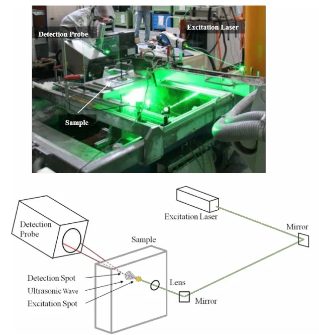
Ultrasound Generation: A powerful, pulsed Nd-YAG laser (532nm wavelength, 6ns pulse time) was used to generate ultrasonic waves. When the high-energy laser pulse illuminates the sample, a fraction of the energy is absorbed, causing local heating, thermal expansion, and ablation. This process induces broadband ultrasonic waves that propagate through the aluminum slab.
Ultrasound Detection: A highly sensitive two-wave beam mixing interferometer (1064nm) was used as a laser ultrasound detector. This device remotely senses the ultrasonic waves as they arrive at the sample surface, allowing for completely contact-free measurement.
The researchers tested two main configurations:
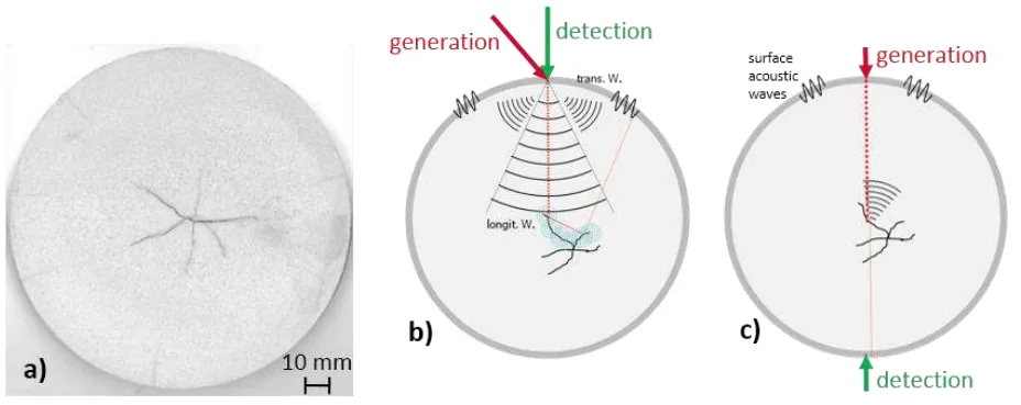
* Transmission Configuration: The excitation laser and detection laser are positioned on opposite sides of the slab. This setup is ideal for detecting the presence of a defect, as any inhomogeneity will disturb the path of the longitudinal bulk wave.
* Reflection Configuration: The excitation and detection spots are at the same location. In this mode, ultrasonic waves travel through the material, reflect off the back wall or any internal defects (like cracks), and return to the detector. This provides more detailed information about the defect's characteristics.
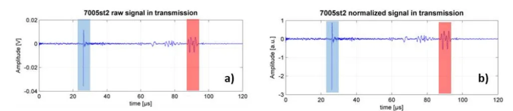
To ensure comparability across measurements, the raw signal was normalized to the amplitude of the Surface Acoustic Wave (SAW), which serves as a consistent measure of excitation and detection efficiency.
The Breakthrough: Key Findings & Data
The experiments successfully demonstrated a clear distinction between defect-free slabs and those with solidification cracks, proving the viability of LUS for industrial quality control.
Finding 1: Clear Differentiation Between Defect-Free and Cracked Slabs
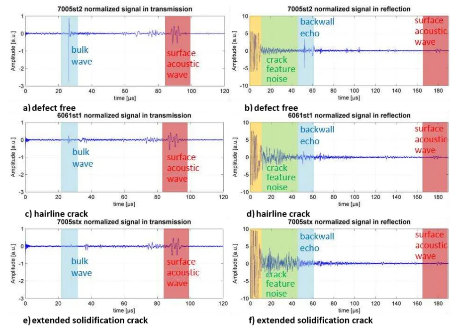
The transmission measurements provided unambiguous evidence of internal defects. As shown in Figure 4, the longitudinal bulk wave in a defect-free sample experienced practically no damping (Fig. 4a). In contrast, a sample with a centered hairline crack showed a moderately damped bulk wave (Fig. 4c). For a sample with extended solidification cracks, the damping was enormous, leading to a nearly total extinction of the bulk wave at the detection spot (Fig. 4e). This high sensitivity makes the transmission configuration excellent for rapid go/no-go quality checks.
Finding 2: Reflection Mode Provides Deeper Insights into Defect Characteristics
While transmission mode is sensitive for detection, the reflection configuration offers more detailed information. For a defect-free sample, a clear back-wall echo is visible with very low "microstructure noise" (Fig. 4b). When a hairline crack is present, the back-wall echo is moderately damped, and a distinct "crack feature noise" appears (Fig. 4d). This noise is the signal from the ultrasonic waves scattering off the crack's interface. For extended cracks, the back-wall echo is highly damped, but the crack feature noise becomes significantly more pronounced (Fig. 4f). This data can be used to gather more information about the crack's features and elongation, even when the crack is too large to permit a back-wall echo.
Practical Implications for R&D and Operations
- For Process Engineers: This study suggests that implementing an inline LUS system in a transmission configuration provides a sufficient and highly sensitive method for detecting solidification cracks in real-time. This enables the immediate application of counteractions to minimize crack expansion and allows for real-time process parameter monitoring and optimization.
- For Quality Control Teams: The data in Figure 4 illustrates a robust method for differentiating between defect-free slabs and those with varying degrees of cracking. The reflection setup, by analyzing the "microstructure noise," enables the interpretation of crack structure and elongation, offering a more detailed quality assessment beyond simple detection.
- For Design Engineers:
Paper Details
Detection of Casting Defects in Aluminum Slabs by Laser Ultrasonic Measurements
1. Overview:
- Title: Detection of Casting Defects in Aluminum Slabs by Laser Ultrasonic Measurements
- Author: Jürgen ROITHER, Thomas MITTER, Bernhard REITINGER, Alois WIESINGER, Christian HOFER, Hubert GRÜN, Peter BURGHOLZER
- Year of publication: 2016
- Journal/academic society of publication: 19th World Conference on Non-Destructive Testing 2016
- Keywords: Laser Ultrasound (LUS), casting defects, aluminum slabs, solidification cracks, non-destructive testing, continuous casting, remote sensing
2. Abstract:
In respect to economization of energy and raw materials the avoidance and real-time detection of defects is a crucial issue in the continuous casting process. Those defects may occur during solidification of aluminum and become noticeable as bulk cracks as well as surface or near-surface cracks. Similarly, in further production processes the maintenance of a high quality level in high performance aluminum alloys for aerospace and automotive industry is also a fundamental topic. Therefore, a non-destructive remote sensing testing tool for quality inspection during early stage of production is required. In this work the laser ultrasound (LUS) technique is demonstrated for quality inspection of semi-manufactured aluminum products. In LUS high energy short laser pulses illuminate the sample. A fraction of the pulse energy is absorbed at the sample surface, causes local heating and thermal expansion, and induces broadband ultrasonic waves which propagate through the sample. Those waves get reflected or scattered by interfaces (i.e. cracks, blowholes) similar to conventional ultrasonic testing, however, contact- and coupling agent-free. For the detection in a remote manner an industrial laser-vibrometer is used for the sensing of the ultrasonic waves at the sample surface. In particular, the real-time inline detection of arising centered solidification cracks during the casting process of aluminum slabs is experimentally demonstrated. Furthermore, the proof of principle for the detection of the most common occurring casting defects (center, near-surface and surface cracks) is shown with experiments in the industrial environment. This is done by pulse-echo measurements with LUS equipment, focusing on surface acoustic waves and longitudinal bulk waves in the data analysis. In conclusion, LUS technology was used to demonstrate its ability for the detection and identification of different types of defects in semi-manufactured aluminum products. Moreover, LUS during continuous casting is a powerful tool for real-time process parameter monitoring and quality control, although all experiments were carried out in an industrial environment with elevated temperatures, dust, cooling water and vibrations.
3. Introduction:
The continuous direct chill casting process of advanced aluminum alloys is a high sophisticated, energy intense process. The avoidance and rapid detection of occurring solidification cracks in the slab (Fig. 1a) is a crucial issue, in particular for the obtainment of a high quality level in further production processes. Next to the maintenance of high-leveled quality in following production processes, such as rolling, the early detection of solidification cracks is also a matter of economics. Due to the fact that the alloyage of the cast requires the heating of the alloy components to the melting point a lot of energy is applied. The inline quality inspection enables instant crack detection in the casting process of the slab and the knowledge of solidification cracks allows the application of counteractions to minimize the expansion of the crack. Otherwise the defect slab would be used in further production processes and cause quality issues and defective goods. The detection of solidification cracks immediately at the appearance enables the economization of energy, raw material and process time. Due to the fact that the detection has to be done directly after the mould of the casting machine, a remote sensing non-destructive method is required for the inspection of the hot slab.
4. Summary of the study:
Background of the research topic:
The continuous casting of aluminum alloys is an energy-intensive process where solidification cracks can form, compromising quality and leading to economic losses. Real-time, non-destructive inspection is needed to detect these defects at the earliest production stage.
Status of previous research:
Conventional ultrasonic testing requires contact and coupling agents, making it unsuitable for inspecting hot, moving surfaces in a harsh industrial environment. Laser Ultrasound (LUS) is a known remote, non-contact technique.
Purpose of the study:
To demonstrate the ability of the LUS technique to detect and identify different types of casting defects in semi-manufactured aluminum products, specifically for real-time, inline quality inspection during the continuous casting process.
Core study:
The study used an LUS setup in both transmission and reflection configurations to inspect aluminum slab samples with varying degrees of solidification cracks (defect-free, hairline crack, extended crack). The setup was then implemented and tested on an industrial continuous casting machine to verify its applicability in a real-world environment.
5. Research Methodology
Research Design:
The study employed an experimental design comparing LUS measurements on different aluminum samples: a defect-free sample, a sample with a hairline crack, and a sample with extended solidification cracks. Both transmission and reflection measurement configurations were used in a laboratory setting. Subsequently, a transmission setup was implemented on a continuous casting machine for inline validation.
Data Collection and Analysis Methods:
Ultrasonic signals were generated using a pulsed Nd-YAG laser and detected with a two-wave beam mixing interferometer. The primary data collected were the time-of-flight ultrasonic waveforms. The analysis focused on the amplitude of the longitudinal bulk wave and the back-wall echo. Signals were normalized using the Surface Acoustic Wave (SAW) amplitude to ensure consistency. For crack reconstruction, the Synthetic Aperture Focusing Technique (SAFT) was applied to reflection data.
Research Topics and Scope:
The research focused on the detection of centered solidification cracks in semi-manufactured aluminum slabs. The scope included laboratory proof-of-principle experiments to detect center, near-surface, and surface cracks, and an inline demonstration of real-time detection during the continuous casting process in an industrial environment.
6. Key Results:
Key Results:
- LUS can clearly distinguish between defect-free samples, samples with hairline cracks, and samples with extended solidification cracks based on the damping of the ultrasonic bulk wave.
- The transmission configuration is highly sensitive for the detection of a crack's existence, showing a rapid decrease in bulk wave amplitude even for small hairline cracks.
- The reflection configuration provides additional information about crack features and elongation through the analysis of "microstructure noise" (scattered waves from the crack interface).
- The study demonstrated the successful application of the LUS system for inline measurements on a continuous casting machine, confirming its viability in a harsh industrial environment.
- The Synthetic Aperture Focusing Technique (SAFT) applied to reflection data enables a rough determination of the elongation and position of the crack.
Figure Name List:
- Fig. 1. a) cross section of a slab with solidification cracks, b) Reflection configuration: Excitation laser and detection laser are arranged at the same spot. Ultrasonic waves are induced in the sample by an pulsed excitation laser (red), propagate through the sample and get reflected or scattered by interfaces (cracks, blowholes,...). The detection of reflected and scattered ultrasonic waves is realized with a two wave beam mixing interferometer (green). c) Transmission configuration: Excitation laser (red) and detection laser (green) are arranged at the opposite side of the sample.
- Fig. 2. a) Raw signal with longitudinal bulk wave (blue) and surface acoustic wave (red) measured in transmission. b) Normalized signal with longitudinal bulk wave (blue) and surface acoustic wave (amplitude of SAW = 1) (red)
- Fig. 3. The laser beam of the excitation laser is deflected by two mirrors and focused at the sample surface. The laser ultrasound detector probe is focused on the opposite side of the excitation spot.
- Fig 4. a) Transmission measurement of a defect-free sample; practically no damping of the bulk wave (blue); b) Reflection measurement of a defect-free sample, practically no damping of the back wall echo (blue) and low microstructure noise (green); c) Transmission measurement of a sample with a hairline crack; moderate damping of the bulk wave (blue); d) Reflection measurement of sample with a hairline crack, moderate no damping of the back wall echo (blue) and moderate crack feature noise (green); e) Transmission measurement of a sample with extended solidification cracks; enormous damping of the bulk wave (blue); f) Reflection measurement of sample with extended solidification cracks, high damping of the back wall echo (blue) and high crack feature noise (green).
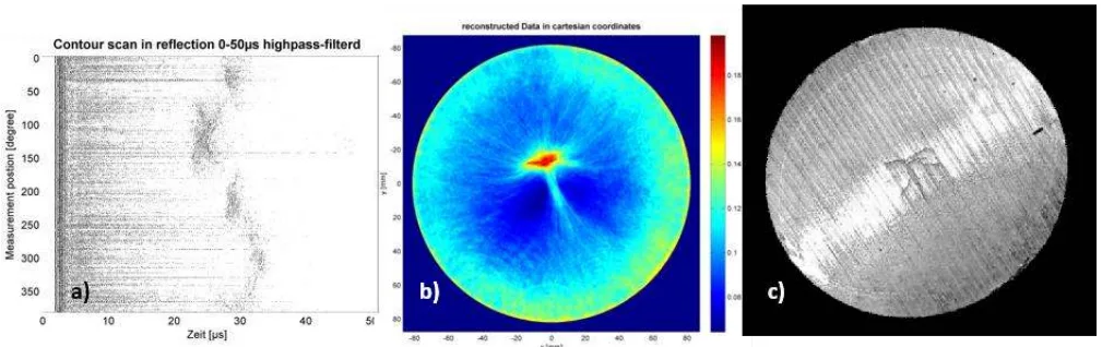
- Fig. 5. a) High-pass filtered signal with micro structure noise b) reconstructed cross section of the sample c) cross section of the sample
- Fig. 6. a) Transmission signal acquired during the casting process b) Transmission signal acquired in the laboratory
7. Conclusion:
The results of the experiments gathered by measurements in the laboratory and during the casting process enable a distinct differentiation of slabs with defects and defect-free samples. The different configuration of the reflection and transmission setup provides different data of the crack feature. The transmission setup is more sensitive for crack detection, but hardly provides any further information about the structure and elongation of the crack. On the other hand the reflection setup enables the interpretation of the microstructure noise for a reconstruction algorithm. Although the reconstruction doesn't show a detailed figure of the crack, the spatial elongation and position can be determined. For the casting process a transmission measurement is sufficient to detect a solidification crack inline. In this case only information whether there is an crack or not is important but no reconstruction is necessary. Additionally tomographic laboratory measurements are important to gain information for the optimization of the casting process.
8. References:
- [1] J. P. Monchalin, IEEE Transactions on Ultrasonics, Ferroelectrics and Frequency Control 33, 485-499 (1986).
- [2] C. B. Scruby and L. E. Drain, Laser Ultrasonics - Techniques and Applications, Bristol, Philadelphia and New York: Adam Hilger, 1990.
- [3] R. J. Dewhurst and Q. Shan, Meas. Sci. Technol. 10, 139-168 (1999).
- [4] S. Zamiri et al., Appl. Phys. B 114, 509-515 (2014).
- [5] L. Chao-Kang, L. Meng-Lin and L. Pai-Chi, Optoacoustic imaging with improved synthetic focusing, Proceedings of SPIE Vol. 5697 pp.255-262, 2005.
Expert Q&A: Your Top Questions Answered
Q1: Why were both transmission and reflection configurations used in the study?
A1: The two configurations provide complementary information. According to the paper's conclusion, the transmission setup is more sensitive for simple crack detection, making it ideal for a quick, reliable inline check. The reflection setup, on the other hand, enables the interpretation of "microstructure noise," which provides more detailed data about the structure, spatial elongation, and position of the crack, making it better suited for detailed laboratory analysis or advanced quality control.
Q2: How did the LUS system perform in the harsh industrial environment of a casting machine?
A2: The paper states that the setup was successfully implemented at a continuous casting machine. The harsh environment, caused by cooling water, dust, and vibrations, was a key challenge. Adaptations were made, such as using a high-pass filter to minimize low-frequency noise from the cooling water. The results, shown in Figure 6, confirm that even in these conditions, the gathered bulk wave signal was good enough to determine the quality of the casted slab inline.
Q3: What is the "microstructure noise" mentioned in the reflection measurements and why is it important?
A3: As described on page 5, the "microstructure noise" is the signal generated by the ultrasound wave scattering at the interface of the solidification cracks. It is not random noise but rather contains valuable information about the crack's features and elongation. By analyzing this signal (highlighted in green in Fig. 4d and 4f), researchers can gain insights into the defect's structure, which is not possible with the transmission method.
Q4: Can this technique precisely reconstruct the size and shape of the crack?
A4: The paper suggests it can provide a general characterization. By applying the Synthetic Aperture Focusing Technique (SAFT) to 360-degree reflection measurements, the researchers achieved a "rough determination of the elongation and position of the crack" (Figure 5). However, the conclusion notes that "the reconstruction doesn't show a detailed figure of the crack," indicating it provides a general location and size rather than a high-resolution image.
Q5: What is the purpose of normalizing the signal to the Surface Acoustic Wave (SAW)?
A5: The paper explains on page 3 that the amount of ultrasonic energy induced and the signal strength depend on the surface's absorption and reflection properties. Since the Surface Acoustic Wave (SAW) propagates along the surface and is similarly affected on all samples, its amplitude can be used as a stable reference for the "excitation and detection efficiency." Normalizing the bulk wave signal to the SAW amplitude (as shown in Figure 2) allows for a more accurate and reliable comparison between different measurements and samples.
Conclusion: Paving the Way for Higher Quality and Productivity
The challenge of detecting internal solidification cracks in real-time during aluminum casting has long been a barrier to optimizing quality and efficiency. This research demonstrates that Laser Ultrasonic Testing provides a robust and powerful solution. By enabling non-contact, inline inspection in harsh industrial environments, this technology allows for the immediate identification of defect-free and defective slabs, paving the way for real-time process control and significant reductions in waste and energy consumption.
At CASTMAN, we are committed to applying the latest industry research to help our customers achieve higher productivity and quality. If the challenges discussed in this paper align with your operational goals, contact our engineering team to explore how these principles can be implemented in your components.
Copyright Information
- This content is a summary and analysis based on the paper "Detection of Casting Defects in Aluminum Slabs by Laser Ultrasonic Measurements" by "Jürgen ROITHER et al.".
- Source: http://ndt.net/?id=19320
This material is for informational purposes only. Unauthorized commercial use is prohibited.
Copyright © 2025 CASTMAN. All rights reserved.