D. T. Peters
Copper Development Association Inc.
Hilton Head Island, SC
J. G. Cowie
Copper Development Association Inc.
New York, NY
E. F. Brush, Jr.
Copper Development Association Inc.
Weston, MA
S. P. Midson
Copper Development Association Inc.
Denver, CO
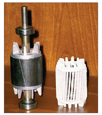
Abstract Little use has been made of pressure die casting for the manufacture of copper or copper alloy parts due in large part to poor economics resulting from short die life in casting these high melting metals. A research program initiated in 1997 was driven by the promise of a signifi cant increase in the energy effi ciency of the induction motor by substituting high conductivity copper for aluminum in the rotor “squirrel cage” structure. Use of high temperature materials including tungsten-, molybdenum- and nickel-base alloys was examined in an extensive series of casting trials. The importance of operating dies at elevated temperatures to minimize the cyclic temperature gradient through the die that leads to heat checking and cracking has been demonstrated by both thermal modeling and experimentation. Shot-by-shot induction melting of the copper charge has been implemented and is described. Performance of motors with die cast copper rotors is compared to that of the aluminum rotor. Preliminary work on the applicability of the hot high temperature die technology combined with semi-solid processing for copper alloy part production is presented.