Use Of High Temperature Die Material Hot Dies For High Pressure Die Casting Pure Copper Copper Alloys

D. T. Peters
Copper Development Association Inc.
Hilton Head Island, SC
J. G. Cowie
Copper Development Association Inc.
New York, NY
E. F. Brush, Jr.
Copper Development Association Inc.
Weston, MA
S. P. Midson
Copper Development Association Inc.
Denver, CO

Presented by: North American Die Casitng Association

Abstract

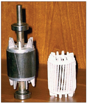
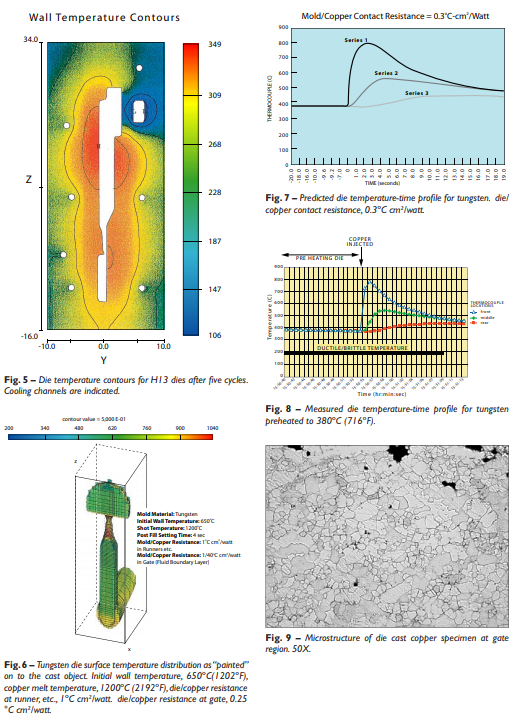
Little use has been made of pressure die casting for the manufacture of copper or copper alloy parts due in large part to poor economics resulting from short die life in casting these high melting metals. A research program initiated in 1997 was driven by the promise of a signifi cant increase in the energy effi ciency of the induction motor by substituting high conductivity copper for aluminum in the rotor “squirrel cage” structure. Use of high temperature materials including tungsten-, molybdenum- and nickel-base alloys was examined in an extensive series of casting trials. The importance of operating dies at elevated temperatures to minimize the cyclic temperature gradient through the die that leads to heat checking and cracking has been demonstrated by both thermal modeling and experimentation. Shot-by-shot induction melting of the copper charge has been implemented and is described. Performance of motors with die cast copper rotors is compared to that of the aluminum rotor. Preliminary work on the applicability of the hot high temperature die technology combined with semi-solid processing for copper alloy part production is presented.

Korea Abstract

구리 또는 구리 합금 부품의 제조를 위한 고압 다이 캐스팅은 거의 사용되지 않았는데, 그 이유는 이러한 고융점 금속을 주조할 때 다이 수명이 짧기 때문에 대부분 경제성이 좋지 않기 때문입니다.

1997년에 시작된 연구 프로그램은 회전자 "squirrel cage" 구조에서 알루미늄 대신 전도성이 높은 구리를 사용하여 유도 전동기의 에너지 효율을 크게 증가시키겠다는 약속에 의해 주도 되었습니다.

텅스텐, 몰리브덴 및 니켈 기반 합금을 포함한 고온 재료의 사용은 광범위한 주조 시험에서 조사되었습니다. 열 검사 및 균열로 이어지는 다이를 통한 주기적인 온도 구배를 최소화하기 위해 고온에서 다이를 작동하는 것의 중요성은 열 모델링과 실험을 통해 입증되었습니다.

구리 전하의 Shot-by-shot 유도 용융이 구현되고 설명됩니다. 다이캐스트 구리 로터가 있는 모터의 성능은 알루미늄 로터의 성능과 비교됩니다. 구리 합금 부품 생산을 위한 반고체 처리와 결합된 고온 고온 다이 기술의 적용 가능성에 대한 예비 작업이 제시됩니다.

Fig. 1 – Typical aluminum rotor and squirrel cage structure after dissolution of the iron laminations.
Fig. 2 – Die material test die made up of six machined inserts.
Fig. 3 – Output of thermal modeling showing H13 die surface “painted” onto the test casting. A) At instant of fi ll with 1200ºC (2192ºF) copper. B) 0.5 sec. after fi ll. C) 6.5sec. after fi ll.
Fig. 4 – Solidifi ed fraction of copper in H13 die at instant of fi ll. B. 0.53 sec. after fi ll.
Temperature Contour and – Microstructure of die cast copper specimen
Fig. 10 – Left--Moving half of TZM and Anviloy die inserts after 940 shots. TZM is in the bottom (left) position and Anviloy in the middle and upper positions. Right--Close up of Anviloy die insert after 500 shots.  Fig. 11 – Schematic illustration of placement of electric resistance heaters and insulation in the die material test set-up developed in the course of this study
Fig. 10 – Left--Moving half of TZM and Anviloy die inserts after 940 shots. TZM is in the bottom (left) position and Anviloy in the middle and upper positions. Right--Close up of Anviloy die insert after 500 shots. Fig. 11 – Schematic illustration of placement of electric resistance heaters and insulation in the die material test set-up developed in the course of this study
Fig. 12 – Horizontal pressure die caster with tooling for rotor casting in closed position. The arbor (dark blue) and the steel rotor laminations (dark gray are shown in the insert and in position in the machine. Copper from the shot sleeve biscuit, runner bar and end rings is shown in yellow. The nickel alloy and ring inserts are shown in medium blue with electrical resistance heater elements in red. These are backed with insulation (pink) as are the runner inserts, which would be nickel alloy or tungsten. Red circles here indicate heater positions. The moveable slide to allow insertion and removal of the rotor is shown in green. Ordinary steel backing plate of the master mold set are shown in light gray. (Courtesy of DieTec,GmbH).
Fig. 13 – Cross-section of rotor for 3-phase motor showing copper filling the conductor bar shots. Fig. 14 – A part produced in three copper alloys by die casting SSM-processed billet.