This introduction paper is based on the paper "Multi-scale simulation of hybrid light metal structures produced by high pressure die casting" published by "IOP Conference Series: Materials Science and Engineering".
1. Overview:
- Title: Multi-scale simulation of hybrid light metal structures produced by high pressure die casting
- Author: J Jakumeit¹, H Behnken¹, R Laqua¹, J Eiken¹ and J Brachmann²
- Year of publication: 2020
- Journal/academic society of publication: IOP Conference Series: Materials Science and Engineering
- Keywords: Not specified in the paper
2. Abstract:
In modern automotive structural components, metal sheets are combined with casting parts to enable a light and mechanical stable structure. In this study, the bonding between steel metal sheets and aluminium casting parts are performed as part of the high pressure die casting (HPDC) process. In this way additional bonding steps like welding can be omitted, which saves time and energy. The combination of sheet metal and cast is achieved by a structured surface (ribs) of the sheet, which is filled in the casting process with the liquid aluminium alloy and leads to a mechanical connection after solidification. Coupled flow and solidification simulation is used to analyse the hybrid casting process with a focus on the rapid solidification inside the ribs. A high-resolution (mesoscale) simulation of the interface between metal sheet and aluminium alloy during filling and solidification can capture the details of melt flow and rapid solidification. By coupling the mesoscale flow and solidification simulations to multiphase field simulations on the microscale, the resulting microstructure can be calculated. The solidification conditions inside the ribs as result of the mesoscale simulation can be validated by comparing the calculated microstructure with experimental results found in real castings, performed on a cold-chamber HPDC machine.
3. Introduction:
High pressure die casting (HPDC) is an important manufacturing process for large, thin-walled structural parts, especially in the automotive industry. HPDC allows the fabrication of complex large aluminium or magnesium parts, which can be more efficient than combining several forged metal sheets by welding. An interesting new application is the combination of aluminium casting and metal sheets in one hybrid casting process step. In this way additional bonding steps like welding can be omitted, which saves time and energy. The combination of sheet metal and cast is achieved by a structured surface (ribs) of the sheet, which is filled during the casting process with the liquid aluminium alloy and leads to a mechanical connection after solidification. The mechanical connection is stronger than glued connections but weaker then welded ones. Important for the connection strength is the complete filling of the structural surface of the metal sheet.
Simulation of the HPDC filling process is challenging due to the very fast and chaotic filling of the cavity with a significant amount of air entrainment. Most commercial simulation programs use a one-phase approach to describe casting processes [1-4] with some special models to approximate the effect of remaining air. In this work a three-phase simulation of casting processes, including the air, melt and solid phases is used. Both, melt and air are considered as compressible fluids separated by a volume-of-fluid approach (VoF), including special treatment to keep the interface sharp. Reduced melt fluidity during the solidification process is handled by a porous media approach to describe the flow through the dendrite network. At a critical solid fraction value, the melt is stopped completely. This approach is implemented in the commercial casting simulation package STAR-CCM+ [5]. Correct treatment of the air and fast solidification which may result in misruns are seen to be important for the investigation of hybrid casting, since air entrainment and melt solidification before complete filling of the structured metal sheet surface can weaken the mechanical bond between metal sheet and casting.
4. Summary of the study:
Background of the research topic:
Modern automotive components require lightweight yet mechanically stable structures. Combining metal sheets (e.g., steel) with cast light metal parts (e.g., aluminium) in a single High Pressure Die Casting (HPDC) process, known as hybrid casting, offers potential advantages over traditional assembly methods like welding by saving time and energy. The mechanical connection in these hybrid structures is achieved by designing structured surfaces (ribs) on the metal sheet, which are filled by the molten alloy during casting.
Status of previous research:
Simulating the complex HPDC process, especially the rapid filling and potential air entrainment, is challenging. While many commercial codes use single-phase approximations, multi-phase approaches considering air, melt, and solid phases provide a more detailed description. Techniques like the Volume-of-Fluid (VoF) method are used for tracking the free surface, and porous media models combined with flow-stopping criteria are employed to simulate the effect of solidification on fluid flow.
Purpose of the study:
This study aims to analyze the hybrid HPDC process using a multi-scale simulation approach, focusing specifically on the melt flow, filling dynamics, and rapid solidification occurring within the small-scale ribs on the metal sheet surface. A key goal is to understand the factors influencing complete rib filling, which is critical for the mechanical integrity of the hybrid joint. Furthermore, the study seeks to validate the simulation results by comparing the predicted microstructure within the ribs against experimental observations from actual castings.
Core study:
The core of the study involves a multi-scale simulation strategy. First, a macroscale simulation of the entire HPDC process provides realistic boundary conditions (melt velocity and temperature) for a subsequent high-resolution mesoscale simulation. This mesoscale simulation focuses specifically on the ribbed interface region between the steel sheet and the aluminium alloy (Al-5wt%Mg-1.8wt%Si). It employs a three-phase (air, melt, solid) VoF model to capture the detailed filling and solidification behaviour within the 0.2 x 0.2 mm ribs. The thermal conditions (cooling rates) predicted by the mesoscale simulation are then used as input for microscale phase-field simulations (using MICRESS® software) to calculate the expected microstructure. The study systematically investigates the influence of different process parameters (rib orientation relative to flow, cavity thickness above the ribs, melt velocity) and solidification models (Scheil approximation vs. phase-field derived fraction solid curve) on the rib filling process. Finally, the simulated microstructure is compared with experimental results from hybrid castings produced on a cold-chamber HPDC machine for validation.
5. Research Methodology
Research Design:
The study employed a multi-scale simulation approach combined with experimental validation. A macroscale simulation of the full HPDC process provided boundary conditions for a detailed mesoscale simulation of the critical ribbed interface. Results from the mesoscale simulation (specifically, local solidification conditions) were then used as input for microscale phase-field simulations to predict the resulting microstructure. These simulation predictions were validated by comparing them with the microstructure observed in experimental hybrid castings produced under defined conditions.
Data Collection and Analysis Methods:
- Simulation:
- Macroscale and Mesoscale: A finite-volume method implemented in STAR-CCM+ was used. This involved solving transport equations for mass, momentum, and energy using a three-phase (air, melt, solid) Volume-of-Fluid (VoF) model with a High-Resolution Interface Capturing (HRIC) scheme. Surface tension was handled via the Continuum Surface Force (CSF) model. Solidification was modelled using a tabulated fraction solid vs. temperature curve (fs(T)) to release latent heat (L*d(fs(T))/dT). Flow resistance in the mushy zone was modelled using a porous media approach based on the Kozeny-Carman equation, incorporating secondary dendrite arm spacing (SDAS, λ2). A flow-stop functionality was implemented to halt melt flow above a critical solid fraction threshold. Material data was sourced from the STAR-CCM+ metallurgy database and thermodynamic calculations.
- Microscale: Phase-field simulations were performed using MICRESS® software in the thin-interface limit, incorporating anti-trapping terms and FD-correction. Material data for the liquid, fcc-Al, and Mg2Si phases were evaluated using the thermodynamic database TCA15 via the TQ-interface. The eutectic was treated as an effective phase.
- Experiment: Hybrid castings were produced using an Al-5wt%Mg-1.8wt%Si alloy cast onto a steel sheet with a ribbed surface structure. A Buehler H630-SC HPDC machine was used with specific process parameters (casting temperature 680 °C, max piston speed 1 m/s, die preheating 200 °C, intensification pressure 200 bar). The microstructure of the resulting castings in the ribbed region was analyzed experimentally for comparison with simulations.
Research Topics and Scope:
The research focused on simulating the filling and solidification of an Al-Si-Mg alloy within 0.2 x 0.2 mm ribs on a steel sheet during a hybrid HPDC process. The scope included:
- Developing and applying a multi-scale simulation workflow (macro-meso-micro).
- Analyzing the melt flow dynamics, temperature evolution, and solidification sequence within the ribs using mesoscale simulation.
- Investigating the influence of process variations on rib filling, specifically:
- Orientation of ribs relative to melt flow (parallel vs. perpendicular).
- Thickness of the casting cavity above the ribs (2 mm vs. 5 mm).
- Melt inlet velocity (standard vs. 4 m/s).
- Solidification model (Scheil approximation vs. fs(T) curve from phase-field simulation).
- Predicting the microstructure within the ribs using phase-field simulation based on mesoscale results.
- Validating the mesoscale simulation's predicted solidification conditions by comparing simulated and experimental microstructures.
6. Key Results:
Key Results:
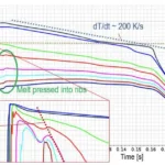
- The mesoscale simulation revealed very rapid cooling rates (~5000 K/s) and solidification within the ribs due to contact with the cold die and sheet metal, while the melt just above the ribs cooled much slower (~200 K/s).
- Complete filling of the ribs was found to occur relatively late in the process, primarily driven by the pressure build-up phase after the main cavity is largely filled (around 60 ms in the simulated case).
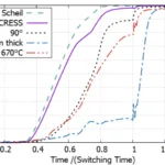
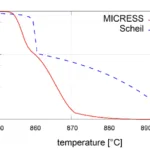
- Using a more realistic fraction solid curve derived from phase-field simulations (incorporating 20 K undercooling) resulted in a later start of solidification and slightly slower rib filling compared to using the simpler Scheil approximation.
- Process parameters significantly influenced rib filling efficiency (compared at the switching time to pressure build-up):
- Ribs oriented perpendicular (crosswise) to the main melt flow filled significantly less effectively (89%) compared to ribs oriented parallel to the flow (98-99%).
- Increasing the thickness of the casting cavity above the ribs from 2 mm to 5 mm drastically reduced rib filling (down to 16%), indicating that pressure build-up is less effective in thicker sections.
- Increasing the melt inlet velocity (to 4 m/s) also reduced rib filling (to 79%), as the faster flow tended to pass over the ribs rather than filling them.
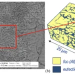
- Microscale phase-field simulations, using thermal conditions extracted from the mesoscale simulation (heat extraction rate 2x10¹¹ W/m³), produced a microstructure (fcc-Al and eutectic) that showed good agreement with the experimental microstructure when a nucleation density of 5x10¹⁶ m⁻³ was assumed. This agreement validates the solidification conditions predicted by the mesoscale model.
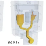
- Figure 2. Simulation of the HPDC process coupling flow, temperature and solidification. After ~0.1 s (b) the critical region below the metal sheet is filled. After 0.2 s (c) the melt in the metal sheet area starts to solidify (green line = points at liquidus temperature).
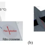
- Figure 3. (a) Mesoscale geometry of the region below the metal sheet with 0.2 x 0.2 mm ribs and (b) the trimmed fine mesh. The round shape of the region with ribs gives possibility to use different orientations towards the melt flow direction.
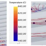
- Figure 4. Streamlines showing the movement of the ribs and the temperature of the melt during the filling process after 25 ms.
- Figure 5. Cooling curves at different points inside (negative position) and above the ribs (positive position). The small sketch at the right shows the positions of the data recording points.
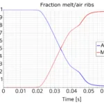
- Figure 6. Volume fraction of melt (red) or air (blue) during filling.
- Figure 7. Filling of ribs using different fraction-solid curves, process parameters or geometries (broken lines use Scheil approximation).
- Figure 8. Fraction solid curves from Scheil approximation and phase-field simulation using MICRESS®.
- Figure 9. A series of phase-field simulations were performed under systematic variation of cooling and nucleation conditions. Good agreement between (a) experimental microstructure and (b) simulated microstructure was obtained for an extraction rate of 2×10¹¹ W/m3 and a nucleation density of 5×10¹⁶ m-3 .
Figure Name List:
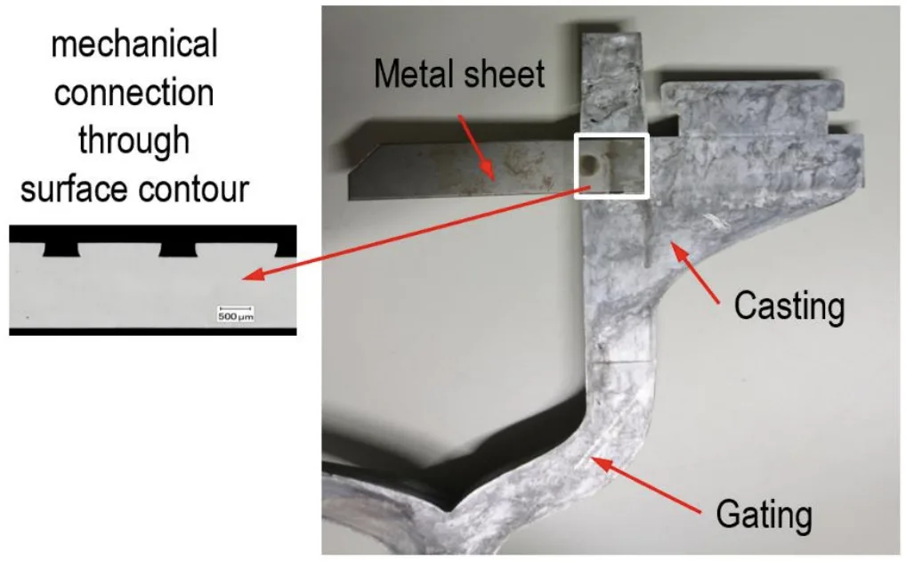
- Figure 1. Hybrid HPDC casting with gating system, casting and metal sheet. The metal sheet is connected to the casting by the surface contour of the metal sheet (ribs), which is filled by the melt.
- Figure 2. Simulation of the HPDC process coupling flow, temperature and solidification. After ~0.1 s (b) the critical region below the metal sheet is filled. After 0.2 s (c) the melt in the metal sheet area starts to solidify (green line = points at liquidus temperature).
- Figure 3. (a) Mesoscale geometry of the region below the metal sheet with 0.2 x 0.2 mm ribs and (b) the trimmed fine mesh. The round shape of the region with ribs gives possibility to use different orientations towards the melt flow direction.
- Figure 4. Streamlines showing the movement of the ribs and the temperature of the melt during the filling process after 25 ms.
- Figure 5. Cooling curves at different points inside (negative position) and above the ribs (positive position). The small sketch at the right shows the positions of the data recording points.
- Figure 6. Volume fraction of melt (red) or air (blue) during filling.
- Figure 7. Filling of ribs using different fraction-solid curves, process parameters or geometries (broken lines use Scheil approximation).
- Figure 8. Fraction solid curves from Scheil approximation and phase-field simulation using MICRESS®.
- Figure 9. A series of phase-field simulations were performed under systematic variation of cooling and nucleation conditions. Good agreement between (a) experimental microstructure and (b) simulated microstructure was obtained for an extraction rate of 2x10¹¹ W/m³ and a nucleation density of 5x10¹⁶ m⁻³.
- Table 1. Filling of ribs using different fraction solid curves or process parameter
7. Conclusion:
A three-phase coupled flow and solidification simulation was successfully used to analyse the hybrid high pressure die casting process combining a metal sheet with a casting, focusing on the rapid solidification within the ribs crucial for mechanical bonding. A high-resolution (mesoscale) simulation captured the details of melt flow and solidification at the interface, using boundary conditions from a macroscale simulation. Coupling the mesoscale simulation results with multiphase-field microstructure simulations (microscale) allowed for the calculation of the resulting microstructure. The good agreement achieved between the calculated microstructure and experimental analysis demonstrated that the mesoscale simulation accurately predicts the solidification conditions inside the ribs.
The systematic investigation of different process configurations yielded the following key findings:
- A pressure build-up phase above the ribs is important for achieving complete filling of the melt into the ribs.
- Melt undercooling (around 20 K, as indicated by phase-field results) leads to a later onset of solidification and increased viscosity, which slightly hinders the fast filling of the ribs compared to simulations using the Scheil approximation.
- Orienting the ribs perpendicular to the melt flow results in later filling compared to parallel orientation, as melt is less likely to flow into the ribs.
- Increasing the thickness of the casting cavity above the ribs hinders the necessary pressure build-up and significantly reduces rib filling. This suggests that thin castings are more favourable for hybrid casting applications than thick parts.
- Higher melt velocities also lead to reduced rib filling, as the melt tends to flow at higher speed over the ribs rather than diverting into them.
8. References:
- [1] The aluminum automotive manual 2002 (European Aluminium Association) https://www.european-aluminium.eu/media/1526/aam-manufacturing-1-casting-methods.pdf
- [2] Beckermann C and Monroe A 2009 Porosity simulation for high pressure die castings Die Casting Engineer (The North American Die Casting Association) ISSN 0012-25JX
- [3] Bodhayana M R and Ramesha N 2014 Int. J. Res. Eng. Tech. 03 (11) 1163
- [4] Zhu J et al. 2009 MCWASP XII (Warrendale: The Minerals, Metals & Materials Society TMS) 361-8
- [5] Jana S, Kättlitz O, Hediger F, Jakumeit J and Aguilar J 2012 IOP Conf. Ser.: Mater. Sci. Eng. 33 012007
- [6] Ferziger J H and Peric M 2002 Computational Methods for Fluid Dynamics (McGraw-Hill) ISBN 2-540-42074-6.
- [7] Teskeredzic A, Demirdzic I and Muzaferija S 2002 Num. Heat Trans. B 42 43
- [8] Demirdzic I and Muzaferija S 1995 Comput. Method Appl. Mech. Eng. 125 235-55
- [9] Muzaferija S and Peric M 1999 Computation of free surface flows using interface-tracking and interface-capturing methods. In Nonlinear Water Wave Interaction, ed Mahrenholtz O et al. (Southampton: WIP Press) pp 59-100
- [10] Brackbill J U, Kothe D B and Zemach C 1992 J. Comput. Physics 100 335
- [11] Sabau S and Viswanath S 2002 Met. Mat. Trans. B 33B 131
- [12] Poirier D R, Yeum K and Mapples A L 1987 Metall. Mater. Trans. A 18 1979
- [13] MICRESS®, multicomponent multi-phase-field software, www.micress.de
- [14] Eiken J, Böttger B and Steinbach I 2006 Phys. Rev. E 73 066122
- [15] Carré A, Böttger B and Apel M 2013 J. Cryst. Growth 380 5
- [16] Eiken J 2012 Mater. Sci. Eng. 33 012105
- [17] Thermo-Calc Software: http://www.thermocalc.com
9. Copyright:
- This material is a paper by "J Jakumeit et al.". Based on "Multi-scale simulation of hybrid light metal structures produced by high pressure die casting".
- Source of the paper: https://doi.org/10.1088/1757-899X/861/1/012035
This material is summarized based on the above paper, and unauthorized use for commercial purposes is prohibited.
Copyright © 2025 CASTMAN. All rights reserved.
