This article introduces the paper "Improvement and validation of Zamak die casting moulds" presented at the Procedia Manufacturing
1. Overview:
- Title: Improvement and validation of Zamak die casting moulds
- Author: H. A. Pinto, F. J. G. Silva, R. P. Martinho, R. D. S. G. Campilho, A. G. Pinto
- Publication Year: 2019
- Publishing Journal/Academic Society: Procedia Manufacturing, Elsevier B.V.
- Keywords: Die casting, Zamak alloys, Moulds, CFD, Computing Fluid Dynamics, Design of moulds, Gas exhaust, Simulation.

2. Research Background:
- Social/Academic Context of the Research Topic: The automotive industry widely uses die-cast parts, including engine blocks and control cable terminals, often made from Zamak alloys. Maintaining quality and minimizing defects in die casting is crucial for meeting automotive industry standards and the goal of zero defects. This aligns with broader industry trends towards continuous improvement and quality management systems like TQM, Lean, and TPS.
- Limitations of Existing Research: While die casting is a reliable process, defects like porosities, incomplete fills, and cracks still occur. Achieving zero defects requires a comprehensive understanding of the entire die casting process, from melting to die filling. Specifically, there's a need to improve methodologies for designing moulds, particularly for small components like control cable terminals.
- Necessity of the Research: To meet the automotive industry's stringent quality requirements and the zero-defect target, research and development are essential. A deeper understanding of the flow process within moulds is needed to improve filling parameters, machine parts, and mould designs, ultimately reducing defects in Zamak die-cast parts like control cable terminals.
3. Research Purpose and Research Questions:
- Research Purpose: The primary purpose is to improve the methodologies for designing moulds for control cable terminals made of Zamak alloys. This involves characterizing the flow within the mould, quantifying porosities, and modifying mould designs to minimize defects.
- Key Research Questions:
- How can the flow of molten Zamak alloy within the die casting mould be characterized during cavity filling?
- How can porosities in Zamak die-cast control cable terminals be quantified?
- What modifications to molten metal flow systems (channels, sprues) and venting systems can reduce porosities and improve part quality?
- How can Computational Fluid Dynamics (CFD) simulations and analytical calculations be used to predict and prevent defects?
- Research Hypotheses: The research hypothesizes that by modifying the molten metal flow systems and introducing venting systems in the die casting mould, the occurrence of porosities and other defects in Zamak control cable terminals can be significantly reduced. It is also hypothesized that CFD simulations can effectively model and predict flow behavior and defect formation, guiding mould design improvements.
4. Research Methodology:
- Research Design: The research follows an empirical iterative process. It starts with analyzing defects in existing parts, then uses CFD simulations to understand the flow, proposes mould improvements, and validates these improvements through further simulations and analysis of parts cast with the modified mould.
- Data Collection Method:
- Defect Analysis: Cut cross-sections of existing Zamak terminals were prepared and analyzed using microscopy and image analysis software (Image J®) to quantify porosities.
- CFD Simulations: FLOWCast® software was used to simulate the molten metal flow in the mould, focusing on air fraction, turbulence, and velocity.
- Analysis Method:
- Quantitative Porosity Analysis: Image J® software was used to measure the area percentage of porosities in the cross-sections, following the Broose 590589-100: 2012 standard.
- CFD Simulation Analysis: Simulation results were analyzed to assess air entrapment, turbulence levels, and flow velocities within the mould cavity for both the original and improved mould designs. Reynolds number calculations were used to characterize flow regimes.
- Research Subjects and Scope: The research focuses on die casting moulds for control cable terminals made of Zamak alloys. The specific terminal geometry analyzed is described as resembling a crank, with a thick central area and an engaging arm. The mould is a two-plate steel mould with inserts made of AISI H13 steel.
5. Main Research Results:
- Key Research Results:
- Initial State Defects: Analysis of initial parts revealed porosities and failures in tensile tests within the functional zones, indicating issues with the feeding process and mould design.
- CFD Simulation Insights: Simulations of the original mould showed turbulent flow, air entrapment, and high velocities, suggesting causes for porosity formation.
- Mould Improvements: Based on simulation results, the mould was improved by:
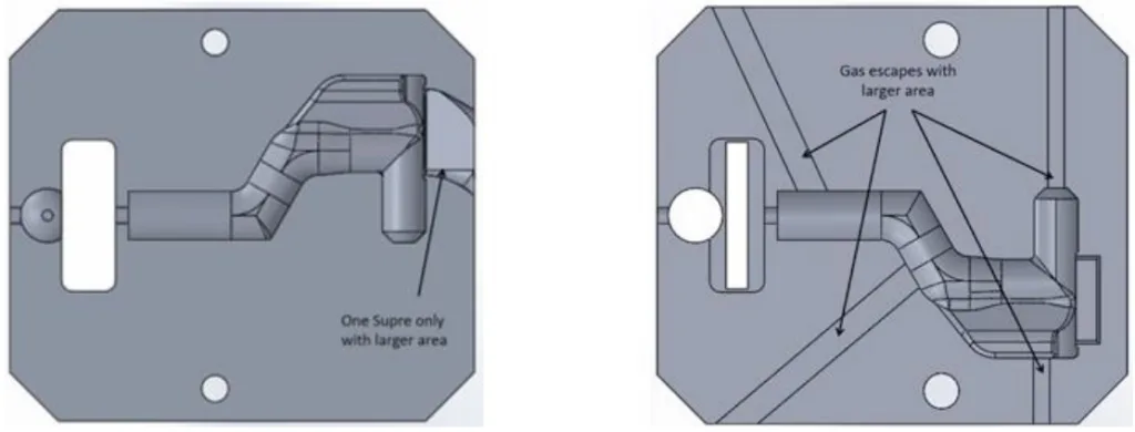
- Venting System: Introducing gas escape channels with a rectangular profile. The escape width (L escape) was set to 0.0255 mm, resulting in a cross-section area (S escape) of 0.0026 mm².
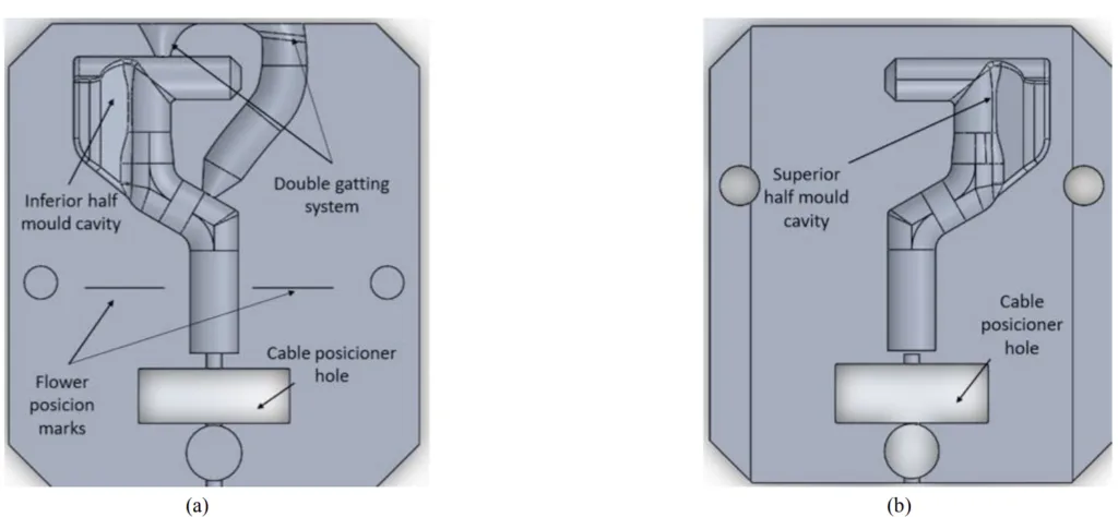
- Gating System Modification: Changing from a double gating system to a single sprue with a larger area to reduce turbulence and flow collision. The sprue section was redesigned with fixed and movable areas to control flow.
- Increased Sprue Dimensions: The area of the sprue section was increased from 4.3 mm² to 5.5 mm².
- Improved Flow and Reduced Porosity: Simulations of the improved mould showed significantly reduced air fraction, turbulence, and velocity during filling.
- Validation of Improvements: Porosity analysis of parts cast with the improved mould showed a substantial decrease in porosity index across all sections and specimens (Table 7). For example, in Specimen 1, Section 1, porosity decreased from 31.7% to 8.5%.
- Statistical/Qualitative Analysis Results: The paper primarily presents quantitative data from simulations and porosity measurements. The comparison of porosity percentages before and after mould improvement (Table 7) demonstrates a clear qualitative improvement in part quality.
- Data Interpretation: The reduction in porosity after mould modifications is attributed to improved gas exhaustion through the venting system and a less turbulent, more laminar flow achieved by the modified gating system and sprue design. The CFD simulations effectively predicted the flow improvements and correlated with the reduced porosity in physical parts.
- Figure Name List:
- Fig. 1. (a) Description of the functional zone of this terminals design; (b) Description of the terminal under study
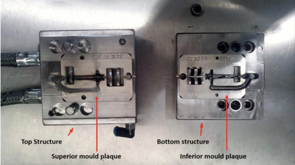
- Fig. 2. Description of the mould structures with the mould inserts docked
- Fig. 3. Description of the mould insert and its systems: (a) lower cavity and (b) upper cavity
- Fig. 4.(a) Plane cut of the terminal for surface analyse; (b) Cut sections selected of the terminal surface; (c) Example of a surface analyse using the Image J software
- Fig. 5. a) Dimensions of the air venting section; b) width and volume calculated for the section
- Fig. 6. Section of the sprue with fixed and movable areas
- Fig. 7. Description of the mould inserts optimized


6. Conclusion and Discussion:
- Summary of Main Results: The study successfully improved the design of a Zamak die casting mould for control cable terminals. CFD simulations guided modifications to the venting and gating systems, resulting in reduced turbulence, improved flow, and a significant decrease in porosity in the cast parts. The validation through porosity analysis confirmed the effectiveness of the implemented improvements.
- Academic Significance of the Research: This research demonstrates the effective application of CFD simulation and iterative design methodology for optimizing die casting mould design. It contributes to a deeper understanding of the relationship between mould design, flow characteristics, and defect formation in Zamak die casting.
- Practical Implications: The improved mould design and methodology can be directly applied to the production of Zamak control cable terminals, leading to higher quality parts with fewer defects and potentially reduced scrap rates. The approach can be adapted for designing moulds for similar small die-cast components. The use of CFD simulation as a design tool can save time and resources in mould development.
- Limitations of the Research: The study focuses on a specific terminal geometry and Zamak alloy. While the methodology is generalizable, the specific design parameters (venting dimensions, sprue geometry) may need to be adjusted for different part geometries and alloys. The paper does not explicitly discuss the cost implications of the mould modifications or the production rate changes.
7. Future Follow-up Research:
- Directions for Follow-up Research:
- Further optimize the venting system design and location for different part geometries and Zamak alloys.
- Investigate the impact of different injection parameters (pressure, velocity) in conjunction with the improved mould design.
- Explore the application of this methodology to other types of die-cast parts and alloys.
- Conduct a more detailed cost-benefit analysis of implementing the mould improvements in a production setting.
- Areas Requiring Further Exploration: The long-term durability and performance of the improved mould in high-volume production could be further investigated. Exploring advanced simulation techniques and incorporating real-time process monitoring could also be beneficial.
8. References:
[1] C. Rosa, F. J. G. Silva, L. P. Ferreira, T. Pereira, R. M. Gouveia, Establishing standard methodologies to improve the production rate of assembly-lines used for low added-value products, Procedia Manufacturing 17 (2018) 555-562.
[2] Brian Cantor, P. Grant, C. Johnston,. Automotive Engineering Lightweight, Functional, and Novel Materials, CRC Press. Philadelphia, U.S.A. 2008. ISBN: 9780750310017.
[3] Khuram Shazhad. Cloud robotics and autonumous vehicles. Autonomous veichles. A. Zak (Editor). InTechOpen, 2016, pp. 0-19. http://dx.doi.org/10.5772/64064.
[4] D. Mann, Automotive Plastics and Composites (2nd ed.). Elsevier Science Ltd. Amsterdam, 1999. ISBN: 9780080527741.
[5] J. Heizer, C. Munson, B. Render, Operations Management, Sustainability and Supply Chain Management (12th ed.). Peaerson. London, 2017. ISBN: 978-0134163512.
[6] H. Santos, M. T. Pereira, F. J. G. Silva, L. P. Ferreira. A Novel Rework Costing Methodology Applied to a Bus Manufacturing Company, Procedia Manufacturing 17 (2018) 631-639.
[7] O. J. Bratz. Push-Pull Cable, United States Patent Office. Patent US3015969A, 1958.
[8] C. Rosa, F. J. G. Silva, L. P. Ferreira, R. Campilho, SMED methodology: the reduction of setup times for Steel Wire-Rope assembly lines in the automotive industry, Procedia Manufacturing 13 (2017) 1034-1042.
[9] B. M. D. N. Moreira, R. M. Gouveia, F. J. G. Silva, R. D. S. G. Campilho, A Novel Concept Of Production And Assembly Processes Integration, Procedia Manufacturing 11 (2017) 1385-1395.
[10] M. A. Boles, Y. A. Çengel, Thermodynamics an engineering approach (5th ed.), McGraw-Hill, Inc., New York, 2014. ISBN: 9780070606593.
[11] S. Memmola, Bowden Cable, United States Patent Office. Patent US4683774A, 1987
[12] C. Rosa, F. J. G. Silva, L. P. Ferreira, Improving the quality and productivity of steel wire-rope assembly lines for the automotive industry, Procedia Manufacturing 11 (2017) 1035–1042.
[13] E. M. G. F. Braga. Otimização do processo de injeção de Zamak (in Portuguese). MSc Dissertation, Master's in Mechanical Engineering, ISEP - School of Engineering, Polytechnic of Porto, Porto, Portugal, 2015.
[14] CMA, Control Cables Design Guide, СМА Cable Manufacturing and Assembly Co, Bolivar, OH, U.S.A. [Online] Available on: https://www.cmacable.com/mechanical-cable/m-guides/control/. Accessed on 15th of February, 2019.
[15] F.J.G. Silva, R. D.S.G. Campilho, L. P. Ferreira, M. T. Pereira, Establishing Guidelines to Improve the High-Pressure Die Casting Process
[16] D. C. C. Ferreira, Mitigação das causas geradoras de defeitos em peças metálicas injetadas de caráter estético (in Portuguese), MSc Dissertation, Master's in Mechanical Engineering, ISEP – School of Engineering, Polytechnic of Porto, Porto, Portugal, 2017.
[17] Ficocables, Zamak Techical Handbook (in Portuguese), Ficocables, Maia, Portugal. 2004.
[18] V. Nunes, F. J. G. Silva, M. F. Andrade, R. Alexandre, A. P. M. Baptista. Increasing the lifespan of high-pressure die cast molds subjected to severe wear. Surface and Coatings Technology, 332 (2017) 319-331.
[19] M. T. Rowley, International atlas of casting defects, American Foundry Association, ASM International, Novelty, OH, U.S.A. 2008. ISBN: ISBN: 978-0874330533.
[20] C. Tian, J. Law, J. van der Touw, M. Murray, J. Yao, D. Graham, D. S. John, Effect of melt cleanliness on the formation of porosity defects in automotive aluminium high pressure die castings, Journal of Materials Processing Technology 122 (2002) 82-93.
[21] Helder Pinto, F. J. G. Silva. Optimization of die casting process in Zamak alloys. Procedia Manufacturing 11 (2017) 517–525.
[22] Brose 590589-100 Standard, 2012.
[23] W. Andresen, Die Casting Engineering: A Hydraulic, Thermal, and Mechanical Process. CRC Press, Boca Raton, FL, U.S.A., 2004. ISBN: 9780824759353.
[24] J. P. S. Ferreira, Simulação numérica e validação experimental de sistemas de enchimento em fundição (in Portuguese), MSc. Dissertation, Mechanical Engineering Department, School of Engineering, University of Minho, 2014.
[25] H.-J. Kwon, H.-K. Kwon, Computer aided engineering (CAE) simulation for the design optimization of gate system on high pressure die casting (HPDC) process, Robotics and Computer Integrated Manufacturing 55(B) (2019) 147-153.
[26] J. Sun, Q. Le, L. Fu, J. Bai, J. Tretter, K. Herbold, H. Huo, Gas entrainment behavior of aluminum alloy engine crankcases during the low-pressure-die-casting process, Journal of Materials Processing Technology 266 (2019) 274-282.
[27] R. M. M. Teixeira, Estudo numérico do efeito dos principais parâmetros de fundição na formação de rechupes em peças fundidas (in Portuguese), MSc dissertation, Department of Industrial Engineering, Polytechnic of Bragança, 2013.
[28] C. Tian, J. Law, J. der Touw, M. Murray, J.-Y Yao, D. Graham, D. St. John, Effect of melt cleanliness on the formation of porosity defects in automotive aluminium high pressure die castings, Journal of Materials Processing Technology 122(1) (2002) 82-93.
9. Copyright:
*This material is H. A. Pinto, F. J. G. Silva, R. P. Martinho, R. D. S. G. Campilho, A. G. Pinto's paper: Based on Improvement and validation of Zamak die casting moulds.
*Paper Source: 10.1016/j.promfg.2020.01.131
This material was summarized based on the above paper, and unauthorized use for commercial purposes is prohibited.
Copyright © 2025 CASTMAN. All rights reserved.
Key Questions & Answers for Researchers:
Q1. What was the primary objective of the research presented in this paper?
The primary objective was to improve the methodologies used to design moulds for control cable terminals in Zamak alloys, with the specific aim of eliminating or significantly reducing defects such as porosity. [Abstract, 2. Methods]
Q2. What were the main types of defects identified in the die-cast parts prior to the mould improvements?
The main defects observed were porosities, which were thought to be caused by failures in the feeding process, including issues with velocities and flow regimes, as well as a suboptimal layout of the feeding systems. [2.4. Description of the problem]
Q3. What were the key modifications implemented in the mould design to address these defects?
The key modifications included the introduction of gas escape channels (a venting system) and an improvement of the gating system, which involved changing from a double sprue to a single sprue with an optimized geometry and a larger injection area to reduce flow collision and turbulence. [3.1 Venting system, 3.2 Gating system, 3.3 Mould improvement]
Q4. How was the effectiveness of the implemented mould improvements validated in the study?
The improvements were validated by comparing CFD simulation results (specifically air fraction, turbulence, and velocity) and by analyzing porosity indexes obtained from micrographic analyses of cut sections of parts produced before and after the mould modifications. [2.5. Framework, 4. Discussion]
Q5. What was the overall impact of the improved mould design on the characteristics of the molten metal flow and the quality of the final cast parts?
The improved mould design resulted in a significant reduction in the amount of air retained within the moulding, a decrease in turbulence levels, and lower velocity during the filling process. [4. Discussion, Table 6] This led to a notable decrease in porosity in the final cast parts. [4. Discussion, Table 7]
Q6. What roles did Computational Fluid Dynamics (CFD) simulations and MATLAB® play in this research?
CFD simulations, using FLOWCast® software, were employed to analyze the flow characteristics inside the mould, including air fraction, turbulence, and injection speed, both before and after mould modifications. [Abstract, 2.7. Description of the simulations] MATLAB® was used to develop an application for mathematical and geometrical calculations to design the venting system and optimize the geometry of the gating system, particularly for determining the ideal Reynolds number. [Abstract, 3.1 Venting system, 3.2 Gating system]