구리 다이캐스팅으로 IE4 효율 수준을 달성하기 위한 15kW, 2극 유도 전동기의 설계 최적화
Abstract
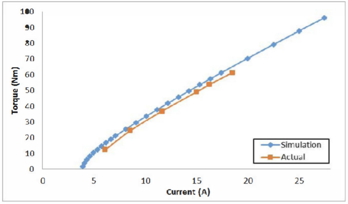
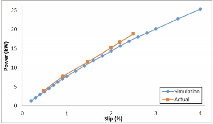
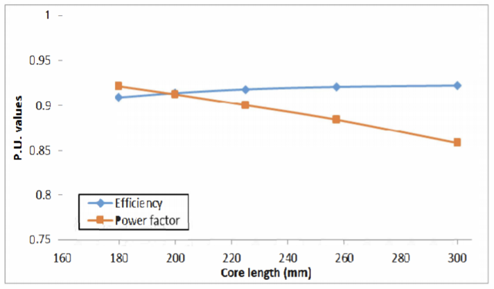
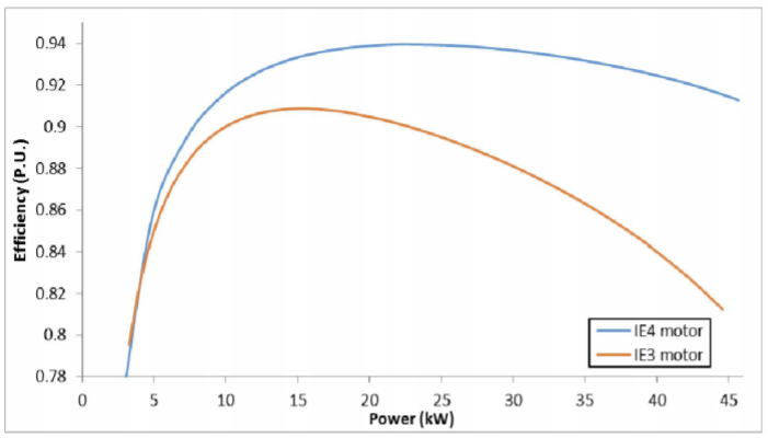
This paper describes the design and simulation of 15 kW, 2 pole, 50 Hz, three phase induction motor to achieve IE4 efficiency level as defined by the International Electrotechnical Commission (IEC). For achieving higher efficiency, the motor is designed, optimized and simulated with copper die-cast rotor and low loss electrical steel. The simulation method is first validated by comparing with the test results of standard IE3 motor. The same simulated model was taken as reference to design the IE4 motor. This design solution having IE4 efficiency is achieved without changing the stator geometry and frame size.
Korea Abstract
본 논문에서는 IEC(International Electrotechnical Commission)에서 정의한 IE4 효율 수준을 달성하기 위한 15kW, 2극, 50Hz, 3상 유도 전동기의 설계 및 시뮬레이션에 대해 설명합니다. 더 높은 효율을 달성하기 위해 모터는 구리 다이캐스트 로터와 저손실 전기강으로 설계, 최적화 및 시뮬레이션되었습니다. 시뮬레이션 방법은 먼저 표준 IE3 모터의 테스트 결과와 비교하여 검증됩니다. 동일한 시뮬레이션 모델이 IE4 모터를 설계하기 위한 참조로 사용되었습니다. IE4 효율성을 갖는 이 설계 솔루션은 고정자 형상 및 프레임 크기를 변경하지 않고 달성됩니다.
Author Keywords

References
Reference
1.Alberti Luigi et al., "Core axial lengthening as effective solution to improve the induction motor efficiency classes", Industry Applications IEEE Transactions on, vol. 1, no. 50, pp. 218-225, 2014.
Show in Context Google Scholar
2.Kim Kwangsoo, Lim Seung-Bin and Ju Lee, "Design of rotor slot of single phase induction motor with copper die-cast rotor cage for high efficiency", Telecommunications Energy Conference 2009. INTELEC, 2009.
Show in Context Google Scholar
3.Boglietti Aldo et al., "Induction motor design methodology based on rotor diameter progressive growth" in Energy Conversion Congress and Exposition (ECCE) 2011, IEEE. IEEE, 2011.
Show in Context Google Scholar
4.Boglietti Aldo et al., "No tooling cost process for induction motors energy efficiency improvements. Industry Applications", IEEE Transactions on, vol. 41.3, pp. 808-816, 2005.
Google Scholar
5.Parasiliti Francesco and Marco Villani, "Design of high efficiency induction motors with die-casting copper rotors" in Energy Efficiency in Motor Driven Systems, Berlin Heidelberg:Springer, pp. 144-151, 2003.
Google Scholar