This article introduces the paper "CAE modelling of cast aluminium in automotive structures" published by Linköping University.
1. Overview:
- Title: CAE modelling of cast aluminium in automotive structures
- Author: Sreehari Veditherakal Shreedhara & Subrat Raman Singh
- Publication Year: 2019
- Publishing Journal/Academic Society: Linköping University, Department of Management and Engineering, Master Thesis in Division of Solid Mechanics
- Keywords: Cast aluminium, Explicit FEA, LS-DYNA, Drop tower, Spring tower, FEM, CrachFEM, MFGenYld
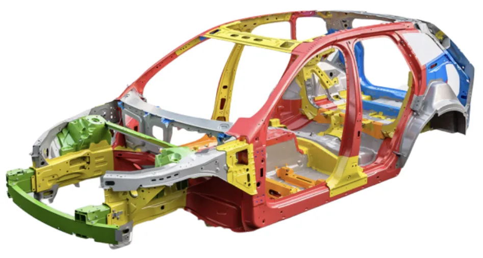
2. Abstracts or Introduction
In the automotive industry, the adoption of Computer Aided Engineering (CAE) solutions is increasingly crucial for engineering decision-making, aiming to replace costly iterative prototyping with a streamlined verification and validation process. However, the inherent variability in material properties, environmental conditions, and the complexities of system physics pose challenges to achieving reliable predictions using deterministic CAE models, particularly in the CAE modelling of cast aluminium components. These components are gaining prominence in automotive structures due to their advantageous mechanical properties, functional integrity, and low weight. Despite these benefits, cast aluminium alloys exhibit specific material behaviors, including porosity and micro-voids from manufacturing, and low ductility, which necessitate advanced numerical models for accurate failure prediction.
This master's thesis investigates the modelling techniques for a cast aluminium alloy component, specifically a spring tower, subjected to a drop tower test. The study aims to validate predicted behavior against physical test results, utilizing the material model provided by MATFEM, currently employed by Volvo Car Corporation (VCC) for cast aluminium parts. The research methodology involves developing boundary conditions for component-level drop tower tests and correlating these with results obtained from various modelling techniques within the explicit solver LS-DYNA. Precise drop tower modelling is emphasized due to its critical influence on simulation outcomes. A detailed Finite Element (FE) model of the spring tower, refined through observations from physical testing, demonstrated good agreement with existing models and physical test data.
3. Research Background:
Background of the Research Topic:
The automotive industry is driven by the imperative to reduce vehicle weight, particularly with the increasing demand for electric vehicles and extended driving ranges. Aluminium alloys are emerging as a material of significant relevance due to their low density and established manufacturing processes [1], offering a viable alternative to heavier steel components and expensive carbon-fiber reinforced plastics. Cast aluminium components, such as spring towers, are integral to automotive Body in White (BIW) structures. However, the complex interplay between material properties, component geometry, and manufacturing processes in cast aluminium introduces challenges in CAE modelling for crash simulations.
Status of Existing Research:
Previous research efforts at VCC included drop testing of cast aluminium spring towers in 2012. However, suboptimal test setups at the time yielded results that did not exhibit component failure as expected, primarily showing ductility. Volvo Cars Corporation currently utilizes the MFGenYld+CrachFEM material model, developed by MATFEM, for CAE analysis of cast aluminium components. This model, while parameterized from extensive coupon tests, requires further validation specifically for cast aluminium components within VCC's applications.
Necessity of the Research:
This research is necessitated by the critical need to validate the applicability of the MFGenYld+CrachFEM material model for accurately simulating the failure behavior of cast aluminium components, particularly spring towers, under impact loading conditions. The study addresses the gap in verified material models for cast aluminium in FE simulations, aiming to enhance the reliability of CAE predictions for these critical automotive components. Furthermore, the investigation explores the computational efficiency and accuracy of different finite element approaches, specifically shell and solid element modelling, for relatively thin-walled cast aluminium structures.
4. Research Purpose and Research Questions:
Research Purpose:
The primary research purpose is to study, verify, and improve CAE modelling methodologies for cast aluminium structures in automotive applications. This encompasses the validation of current modelling and simulation techniques used at Volvo Cars, Gothenburg, Sweden, and the refinement of these methods to enhance the accuracy of failure prediction for cast aluminium components.
Key Research:
The key research focus is on investigating the modelling technique of a cast aluminium alloy spring tower component subjected to a drop tower test. The study aims to validate the predicted structural behavior against physical test results, focusing on the correlation between CAE simulations and experimental outcomes.
Research Hypotheses:
This research seeks to address the following key questions:
- "What is the best failure prediction method for cast aluminium based on the the current computational capabilities?"
- "Will shell and solid elements provide accurate results for relatively thin walled structures ?"
5. Research Methodology
Research Design:
The research design employed a comparative approach, integrating physical experimentation with CAE simulations. Physical drop tower tests were conducted on cast aluminium spring tower components to generate empirical data on structural behavior under impact loading. Concurrently, Finite Element (FE) models of the spring tower were developed using both shell and solid element formulations to simulate the drop tower test conditions.
Data Collection Method:
Physical test data was collected using accelerometers mounted on the impactor during drop tower tests. These accelerometers measured acceleration and deceleration forces upon impact. The data was processed to derive force-displacement curves, which served as the benchmark for validating CAE models. For CAE simulations, LS-DYNA, an explicit finite element solver, was utilized. Simulation outputs included animation data (d3plot files) and numerical data (binout files), which were post-processed using METApost to analyze deformations, plastic strain, and force-displacement relationships.
Analysis Method:
The analysis method centered on the correlation of force-displacement curves obtained from physical drop tower tests and CAE simulations. The accuracy of failure prediction was assessed by comparing the location and mode of failure in physical tests with element deletion patterns and plastic strain distributions in FE models. The study evaluated the influence of various modelling parameters, including element type (shell vs. solid), element formulation (ELFORM02, ELFORM13, ELFORM16), mesh density, and friction coefficients, on the correlation between simulation and experimental results.
Research Subjects and Scope:
The research focused on a cast aluminium spring tower, a critical structural component in automotive BIW. The scope was limited to component-level testing and CAE analysis, specifically within the context of drop tower impact scenarios. The material model employed was MFGenYld+CrachFEM, provided by MATFEM and utilized by Volvo Car Corporation. The study investigated two primary load cases, varying impact velocity and direction, to assess the robustness of the CAE modelling approaches.
6. Main Research Results:
Key Research Results:
The study demonstrated that achieving accurate correlation between CAE simulations and physical drop tower tests for cast aluminium spring towers necessitates meticulous development of the test setup and FE model boundary conditions. Key findings include:
- Boundary Condition Refinement: Modifying the FE model to incorporate a more realistic representation of the drop tower setup, including rollers and guide rails, significantly improved the correlation with physical test results.
- Element Formulation Impact: For shell element models, the fully integrated formulation ELFORM16 exhibited superior performance compared to ELFORM02, providing better agreement with experimental force-displacement curves and failure predictions.
- Shell vs. Solid Element Modeling: Both shell and solid element models demonstrated capability in predicting failure. Solid element models, particularly with finer meshes and ELFORM16, offered more precise prediction of failure location. However, shell element models, computationally more efficient, showed better overall correlation with experimental force-displacement curves.
- Mesh Sensitivity: Solid element models were found to be more sensitive to mesh density. Coarse meshes in solid models tended to overestimate peak forces, indicating a stiffer structural response. Mesh refinement improved accuracy but increased computational cost.
- Friction Coefficient Importance: The friction coefficient between the impactor and spring tower emerged as a critical parameter influencing simulation accuracy. Adjusting friction values, particularly static friction (fs), to 0.25 improved the correlation with physical test data.
Analysis of presented data:
- Force-Displacement Curves: Figures 5.3, 5.4, 5.6, 5.9, 5.10, 5.12, 5.13, 5.17, and 5.19 illustrate the force-displacement curves comparing physical test data with CAE simulation results for various element types, formulations, and friction coefficients under different load cases. These curves demonstrate the improved correlation achieved with refined FE models and optimized parameters.
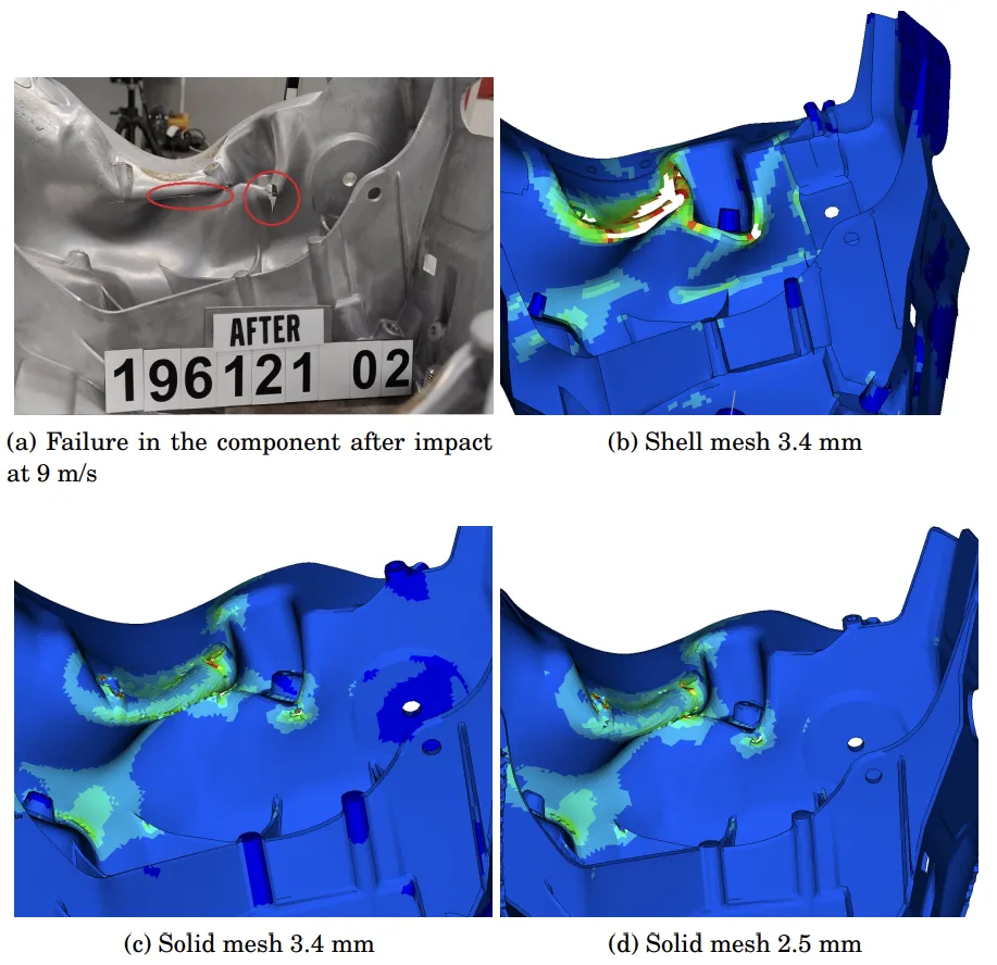
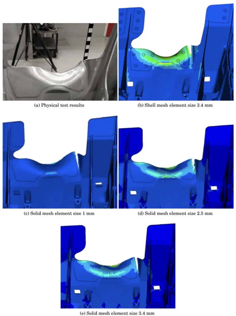
- Failure Mode Comparisons: Figures 5.1, 5.2, 5.5, 5.7, 5.8, 5.11, 5.14, and 5.16 visually compare the failure modes and locations observed in physical tests with those predicted by CAE models. These figures highlight the enhanced accuracy of failure location prediction with solid element models and the overall predictive capability of both shell and solid approaches.
- Computational Efficiency: Figure 4.3 and Table A.2 provide timing information for different FE models, illustrating the computational cost associated with solid vs. shell elements and the impact of mesh density and element formulation on simulation time. Selective mass scaling is shown to be an effective technique for reducing computational time in explicit FE analyses.
Figure Name List:
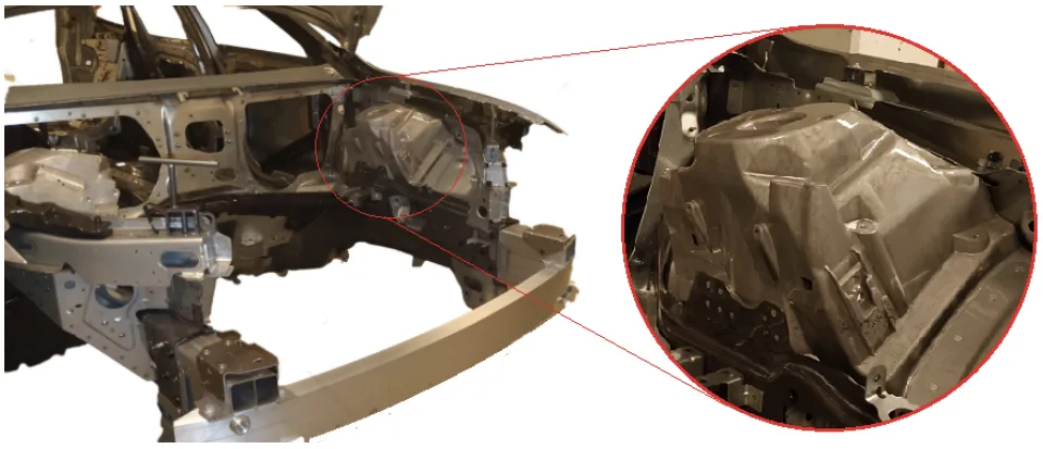
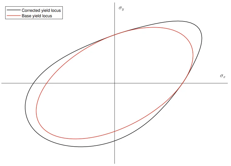
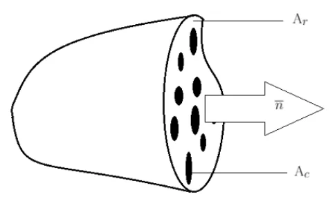
- Figure 1.1: Body materials of a Volvo XC60
- Figure 2.1: Spring tower in Volvo XC60
- Figure 2.2: Previous test setup
- Figure 3.1: Yield locus
- Figure 3.2: Isotropic hardening (left) and Kinematic hardening (right)
- Figure 3.3: Undamaged area Ar, damaged area Ac and normal direction of the surface n
- Figure 3.4: Different failures modes
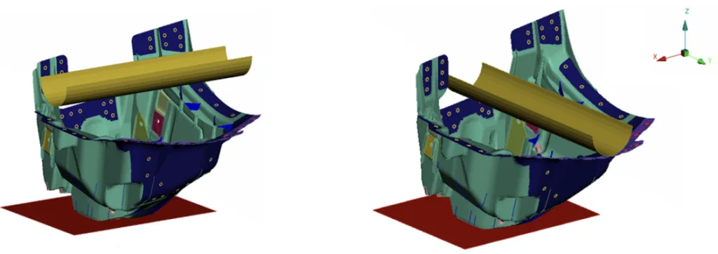
- Figure 4.1: Load case 1 and Load case 2
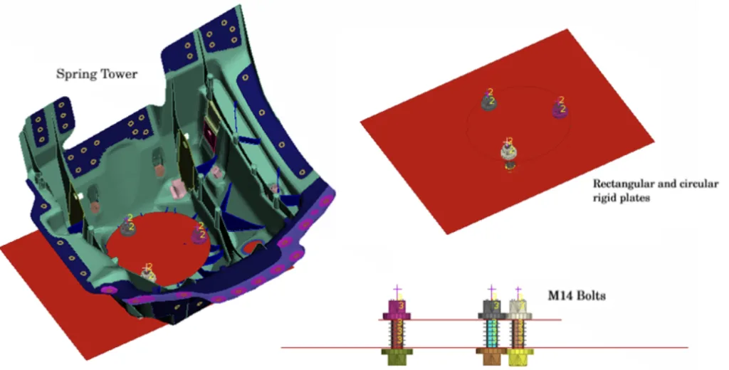
- Figure 4.2: FE model spring tower, plates and bolts
- Figure 4.3: Timing information
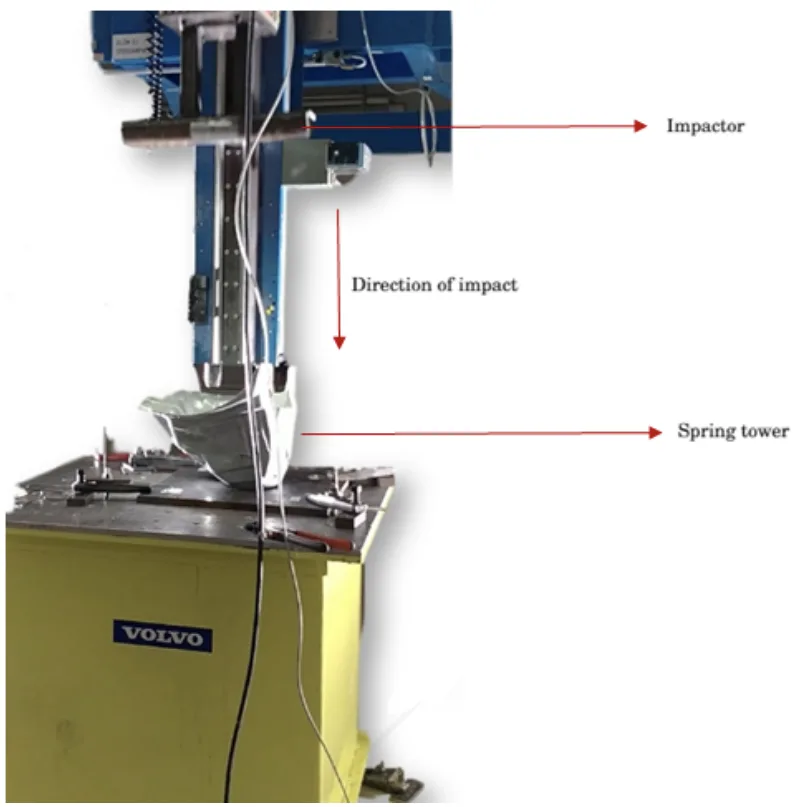
- Figure 4.4: Physical test setup in the drop tower for the second load case
- Figure 4.5: Modified setup for co-relation with solid meshed model of the spring tower
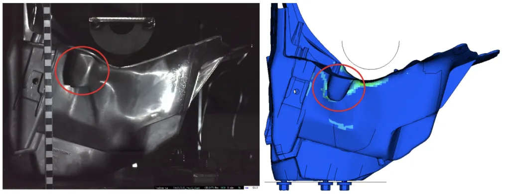
- Figure 5.1: Physical test compared to CAE model with rigid impactor at 6m/s
- Figure 5.2: Incorrect failure prediction in FE model with rigid impactor compared to physical test at 6m/s
- Figure 5.3: Force vs displacement curve of physical and original FE model at 6m/s
- Figure 5.4: Force-displacement curve of physical test with simulations pf shell model at 6 m/s
- Figure 5.5: Failure in FE shell model after impact at 6 m/s with different mesh size
- Figure 5.6: Force-displacement curve of physical test with simulations of solid model at 6m/s
- Figure 5.7: Failure in the FE model with different element size using ELFORM16 at 6 m/s
- Figure 5.8: Failure in the FE model with different element size using ELFORM13 at 6 m/s
- Figure 5.9: Force-displacement curve with shell model at 9 m/s
- Figure 5.10: Force-displacement curve with solid model at 9 m/s
- Figure 5.11: Failure in the physical and the FE model with different element size at 9 m/s
- Figure 5.12: Force-displacement curve with the shell model at 4 m/s
- Figure 5.13: Force-displacement curve with the solid model at 4 m/s
- Figure 5.14: Comparison of physical and FE model with different elements size at 4 m/s
- Figure 5.15: Comparison of physical and FE simulation of load case 2 at 5 m/s
- Figure 5.16: Comparison of physical and FE model at 5 m/s
- Figure 5.17: Force-displacement curve with shell model at 5 m/s
- Figure 5.18: Comparison of solid FE model at 5 m/s
- Figure 5.19: Force-displacement curve with solid model at 5 m/s
- Figure A.1: Failure with rigid impactor at 6 m/s
- Figure A.2: Force-displacement curve with shell model at 7.5m/s
- Figure A.3: Force-displacement curve with solid model at 7.5 m/s
- Figure A.4: Failure in the physical and the FE model with different element size at 7.5 m/s
- Figure A.5: Comparison of Force-displacement curve with shell model at 5 m/s
- Figure A.6: Comparison of Force-displacement curve with solid model at 5 m/s
- Figure A.7: Crack initiation in physical and FE model with different elements size at 5 m/s
- Figure A.8: Force-displacement curve with shell model at 4 m/s
- Figure A.9: Force-displacement curve with solid model at 4 m/s
- Figure A.10: Comparison of the physical and the FE model with various element sizes at 4 m/s
7. Conclusion:
Summary of Key Findings:
The research underscores the significance of a well-designed test setup for accurate correlation between physical and CAE results in drop tower testing of cast aluminium components. The MFGenYld+CrachFEM material model demonstrated good correlation for cast aluminium components when implemented with appropriate FE modelling techniques. Load case 1 test setup proved more effective than Load case 2 for consistent and manageable testing. Both shell and solid element models exhibited capability in predicting failure, with solid models providing more precise failure location prediction, albeit at higher computational cost and mesh dependency. Shell element models, particularly utilizing ELFORM16, offered a computationally efficient approach with good correlation to experimental force-displacement behavior. Selective mass scaling was identified as a viable technique to enhance computational speed in explicit FE analyses without significantly compromising result accuracy. The friction coefficient was highlighted as a critical parameter requiring careful consideration and potentially experimental validation for improved simulation fidelity.
Academic Significance of the Study:
This study contributes to the academic understanding of CAE modelling for cast aluminium components in automotive crashworthiness simulations. It provides a comparative analysis of shell and solid element approaches, offering insights into their respective strengths and limitations for predicting failure in thin-walled cast structures. The research validates the application of the MFGenYld+CrachFEM material model and explores the effectiveness of different element formulations, enriching the body of knowledge in explicit finite element methods for crash analysis.
Practical Implications:
The findings of this research offer practical guidelines for engineers involved in CAE modelling of cast aluminium automotive structures. The study emphasizes the importance of:
- Developing realistic FE model boundary conditions that accurately represent physical test setups.
- Selecting appropriate element formulations, with ELFORM16 recommended for shell element modelling of cast aluminium under impact.
- Considering the trade-offs between computational cost and accuracy when choosing between shell and solid element models, with shell elements offering a computationally efficient yet reasonably accurate approach.
- Recognizing the sensitivity of solid element models to mesh density and the need for mesh refinement for accurate results.
- Accounting for friction at contact interfaces as a critical parameter in CAE simulations of impact events.
Limitations of the Study and Areas for Future Research:
The study's limitations include its focus on a single component, the spring tower, and specific drop tower test conditions. The frictional values used in simulations were estimations and not experimentally derived. Future research directions include:
- Expanding the validation study to a broader range of cast aluminium components and loading scenarios to generalize the findings.
- Conducting experimental investigations to determine accurate frictional coefficients for cast aluminium interfaces under impact conditions.
- Exploring the performance of other advanced element formulations and damage models for enhanced failure prediction accuracy in cast aluminium simulations.
- Investigating the influence of material variability and manufacturing-induced defects, such as porosity, on the CAE modelling of cast aluminium components.
8. References:
- [1] Djukanovic G. Aluminium vs. steel in electric vehicles : the battle goes on. Aluminium insider; 2018. https://aluminiuminsider.com/aluminium-vs-steel-in-electric-vehicles-the-battle-goes-on/.
- [2] Lambert F. Volvo clarifies electrification plan, aims for 50 percent of sales to be fully electric by 2025. electrek; 2018. https://electrek.co/2018/04/25/volvo-electrification-plan-fully-electric/.
- [3] Dharwadkar N, Adivi KP. Modelling of Engine suspension components for crash simulation. Division of Vehicle safety, Department of Applied mechanics, Chalmers University of technology; 2014.
- [4] Dell H, Gese H, Oberhofer G. MF GenYID + CrachFEM User's theory Manual. 2014;.
- [5] Stouffer DC, Dame LT. Inelastic deformation of metals. 1st ed. John Wiley and Sons; 1996.
- [6] Björklund O. Ductile failure in High Strength Steel Sheets. Linköping University; 2014.
- [7] Xue L. Damage accumulation and fracture initiation in uncracked ductile solids subject to triaxial loading. 2006;.
- [8] Brenner F, Buckley M, Gese H, Oberhofer G. Influence of discretisation on stiffness and failure prediction in crashworthiness simulation of automotive high pressure die cast components. 9th European LS-DYNA Conference. 2013 Feb; Available from: https://www.dynalook.com/conferences/9th-european-ls-dyna-conference.
- [9] Hallquist J. LS-DYNA theory manual. Livermore Software Technology Corporation, California; 2006.
- [10] Olovsson L, Simonsson K, Unosson M. Selective mass scaling for explicit finite element analyses. 2005;.
- [11] Erhart T. Review of solid element formulations in LS-DYNA. LS-DYNA forum 2011; 2011.
- [12] Cook RD, Malkus DS, Plesha ME. Concepts and Applications of Finite Element Analysis, 3rd Edition. 3rd ed. Wiley Student Edition; 2004.
9. Copyright:
- This material is "SHREEHARI VEDITHERAKAL SHREEDHARA"'s paper: Based on "CAE modelling of cast aluminium in automotive structures".
- Paper Source: [DOI URL] (No DOI URL provided in the document, please add if available)
This material was created to introduce the above paper, and unauthorized use for commercial purposes is prohibited.
Copyright © 2025 CASTMAN. All rights reserved.