A Breakthrough in Shotblast Resistant Laser Marking: Achieving Indestructible Traceability for Die Cast Parts
This technical summary is based on the academic paper "Inline Integration of Shotblast Resistant Laser Marking in a Die Cast Cell" by J. Landry¹, J. Maltais¹, J-M. Deschênes¹, M. Petro², X. Godmaire¹, A. Fraser¹, published in NADCA (2018).
Keywords
- Primary Keyword: Shotblast Resistant Laser Marking
- Secondary Keywords: Die Casting Traceability, Inline Part Marking, 2D Data Matrix, Automotive Component Traceability, Laser Engraving Aluminum, NADCA
Executive Summary
- The Challenge: Standard laser-marked traceability codes on die cast parts are completely erased by common post-processing steps like shotblasting, making robust, cradle-to-grave part tracking impossible.
- The Method: Researchers systematically tested various laser marking parameters—including cell depth, cell size, and a novel "cell filling ratio"—on aluminum die castings before subjecting them to an aggressive shotblast process.
- The Key Breakthrough: An optimal set of parameters was identified, proving that creating a grid of partially filled, deep-enough cells (rather than fully engraved squares) allows the 2D code to withstand shotblasting and remain perfectly readable.
- The Bottom Line: For the first time, die-casters can integrate a fast, robust laser marking process directly into the casting cell, guaranteeing 100% part traceability even after aggressive surface finishing.
The Challenge: Why This Research Matters for HPDC Professionals
In the automotive industry, the cost of recalls is staggering. The ability to trace every single component back to its exact production time and process parameters is no longer a luxury—it's a necessity. For high-integrity die castings, this means applying a unique 2D data matrix code to each part. The problem? To be effective, this marking must happen immediately after casting, inside the cell, to prevent any mix-ups.
However, 25% to 50% of these parts then undergo shotblasting to smoothen their surface. This aggressive process, which pelts the component with steel shot, completely obliterates conventional laser markings, destroying all traceability. For years, the industry has struggled with this challenge: how do you create a permanent mark that can survive the very process designed to alter the part's surface? This research was undertaken to solve that exact problem.
The Approach: Unpacking the Methodology
To find a shotblast-proof marking solution, the research team conducted a rigorous, multi-stage experiment. Their approach was methodical, designed to isolate and optimize the key variables influencing mark survivability.
Method 1: Initial Hypothesis Testing
The initial theory was that creating very small, deep cells—smaller than the diameter of the shotblast media—would physically protect the blackened, absorptive surface at the bottom of the cell.
- Equipment: A Laserax LXQ-100 (100W) fiber laser was used to mark 2D Data Matrix Codes (DMCs) on an aluminum alloy (Aural 2™, with 8-10% Si).
- Process: Samples with varying small cell sizes were marked and then subjected to shotblasting in a Viking Blast (model: CB-3614).
- Analysis: The readability of the codes was evaluated post-shotblast.
Method 2: Parameter Optimization with "Cell Filling Ratio"
After the initial hypothesis failed, researchers developed a new concept: the "cell filling ratio." Instead of engraving a full square for each black cell in the code, they engraved a smaller square inside it, leaving a protective "wall" of original material around each mark.
- Equipment: The same Laserax LXQ-100 laser was used, along with a Wheelabrator Tumblast with S170 cast steel ball shot (average diameter 0.430 mm).
- Variables: A total of 85 DMCs were created, all with an 80% filling ratio. The key variables tested were cell size (from 0.3 mm to 1.6 mm) and marking depth (controlled by making 1 to 5 laser passes).
- Analysis: Mark quality was quantified before and after the 90-second shotblast process using a Cognex DM262X camera, which calculated contrast and assigned an overall grade based on the ISO 29158 standard.
The Breakthrough: Key Findings & Data
The systematic approach yielded clear, actionable results that overturned initial assumptions and established a new best practice for durable laser marking.
Finding 1: Small Cells Fail Due to Material Deformation
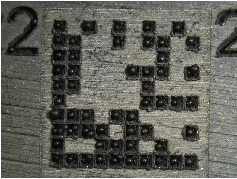
The initial hypothesis was proven incorrect. Instead of protecting the mark, the impact of the steel shot on the soft aluminum surface caused the material to deform and flow, completely clogging the small holes. As shown in Figure 6, this "smoothening" effect rendered the code entirely unreadable. This demonstrated that simply making the holes smaller than the shot was not a viable solution.
Finding 2: The "Cell Filling Ratio" is the Key to Survival
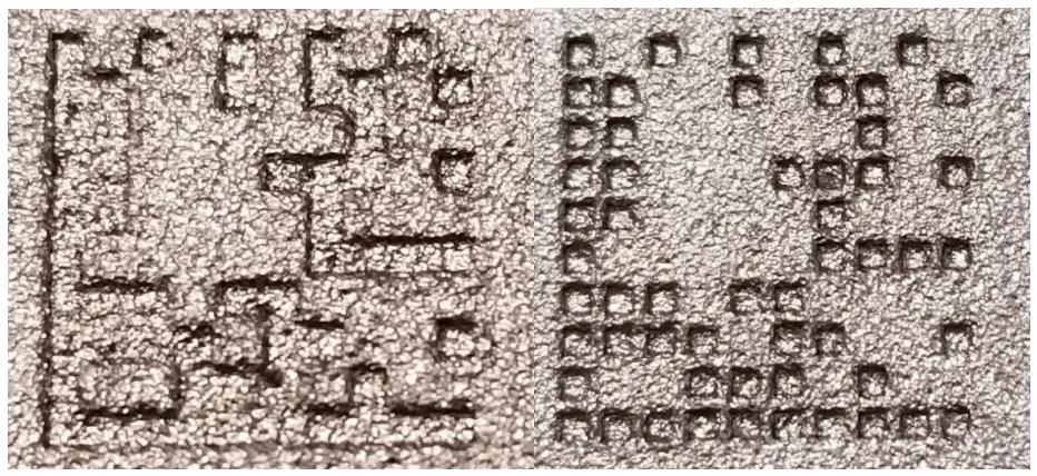
The introduction of a wall around each cell was the critical innovation. This wall acts as a buffer, absorbing the impact and protecting the inner marked surface. Figure 10 provides a stark visual comparison: the 100% filled DMC on the left is heavily damaged after shotblast, while the 80% filled DMC on the right maintains excellent contrast and readability. This confirmed that preserving a separating wall between cells is essential for preserving the code.
Finding 3: An Optimal Window for Cell Size and Depth Ensures Readability and Speed
The research identified a "sweet spot" for marking parameters that balances survivability with the speed required for inline integration.
- Cell Size: As seen in the data from Figure 15, cells smaller than 0.5 mm were unreadable. The optimal contrast was achieved in a range from 0.55 mm to 0.95 mm. Above this, contrast began to decrease again.
- Marking Time: Critically, the study showed that a high-quality, Grade A or B mark could be achieved in under 10 seconds. As detailed in Figure 18, using just two laser passes (approx. 0.30 mm depth) provided excellent results, making the process fast enough for most die casting cycle times.
Practical Implications for R&D and Operations
- For Process Engineers: This study suggests that integrating a laser marker with the correct parameters (cell size ~0.70 mm, 80% fill ratio, 2 passes) is now a feasible solution for 100% inline traceability. Table 6 provides a clear guide on choosing between an Open Air or Turntable enclosure based on available cycle time and data requirements.
- For Quality Control Teams: The data in Table 2 shows the resulting ISO 29158 grade for various parameter combinations post-shotblast. This can inform new quality inspection criteria, ensuring that marked codes not only exist but are guaranteed to be readable after all post-processing is complete.
- For Design Engineers: The findings indicate that a flat surface area large enough to accommodate a DMC with a cell size between 0.55 mm and 0.95 mm should be considered in the part design phase. For a common 14x14 code, this would require a space of roughly 12 mm x 12 mm.
Paper Details
Inline Integration of Shotblast Resistant Laser Marking in a Die Cast Cell
1. Overview:
- Title: Inline Integration of Shotblast Resistant Laser Marking in a Die Cast Cell
- Author: J. Landry¹, J. Maltais¹, J-M. Deschênes¹, M. Petro², X. Godmaire¹, A. Fraser¹ (¹Laserax Inc., ²Cascade Die Casting Group)
- Year of publication: 2018
- Journal/academic society of publication: NADCA (North American Die Casting Association)
- Keywords: Laser Marking, Shotblast Resistant, Die Casting, Traceability, 2D Data Matrix Code
2. Abstract:
High costs from automotive recalls have increased the demand for individual traceability of die castings, often requiring unique 2D data-matrix codes. A key advantage for manufacturers is the ability to trace process parameters for any given part, aiding in process improvement. To ensure correct identification, marking must occur within the die casting cell. However, subsequent shotblast processes, which are common for these parts, are aggressive and typically erase marks. After three years of study, Laserax has identified laser parameters that enable the marking of identifiers capable of resisting most shotblast processes while maintaining high quality and readability. Recent results demonstrate a fast, robust laser marking method that can be integrated into a die casting cell without compromising throughput. The high reading rates of these identifiers after shotblast enable true traceability for die-casters and facilitate process improvements.
3. Introduction:
The need for individual component traceability has grown significantly, particularly in the automotive industry. The primary challenges for direct part marking of 2D matrices have been reducing marking time to fit within machine cycle times and creating a code resistant to post-casting processes. For die casting, 25% to 50% of components undergo abrasive shotblasting, which completely removes conventional laser marks. Previous work presented at the 2017 NADCA show demonstrated the feasibility of reading a laser-marked 2D code after shotblast. This paper presents a more thorough investigation into parameters such as marking depth and cell size to optimize the process for 2D code quality, contrast, and marking time.
4. Summary of the study:
Background of the research topic:
A Data Matrix Code (DMC) is a 2D code using white and black squares to encode information. The blackening of a metal surface via laser is caused by an increase in local surface roughness, which enhances light absorption. Standard shotblasting flattens this rough surface, destroying the contrast and making the code unreadable.
Status of previous research:
Previous studies by the authors (Maltais et al., 2016) established the mechanism of laser-induced surface blackening. A preliminary demonstration of a readable post-shotblast 2D code was presented by Laserax at the 2017 NADCA show, which prompted the more thorough investigation detailed in this paper.
Purpose of the study:
The study aimed to identify and optimize laser marking parameters to create a 2D data matrix code on aluminum die castings that would remain readable after an aggressive shotblast process, and to do so within a cycle time suitable for inline integration in a die cast cell.
Core study:
The core of the study was to create a shotblast resistant DMC by engraving deep cells where the outer walls would geometrically protect the black, absorptive microstructure at the bottom from the shotblast media. The study systematically varied cell size, marking depth, and cell fill ratio to determine the optimal parameters for post-shotblast readability, contrast, and overall grade according to ISO 29158.
5. Research Methodology
Research Design:
The research followed an iterative experimental design. An initial hypothesis—that cells smaller than the blast media would be protected—was tested and disproven. A second, more comprehensive experiment was then designed to test a new hypothesis based on a partial "cell filling ratio." This involved creating 85 sample markings on an aluminum alloy, systematically varying cell size and depth, while keeping the filling ratio constant at an optimized 80%.
Data Collection and Analysis Methods:
Samples were marked using a Laserax LXQ-100 (100W) fiber laser. Marking depth was physically measured with a DEKTAK 150 surface profiler. After marking, samples were subjected to shotblasting using either a Viking Blast CB-3614 or a Wheelabrator Tumblast with S170 steel shot. Post-shotblast analysis was conducted using a Cognex DM262X camera, which measured contrast according to the ISO 29158 standard and assigned an overall quality grade (A through F) to each DMC.
Research Topics and Scope:
The research focused exclusively on laser marking of 2D Data Matrix Codes on an aluminum alloy containing 8-10% Si. The primary variables investigated were the individual cell size of the DMC (0.3 mm to 1.6 mm), the depth of the laser mark (controlled by 1 to 5 laser passes), and the cell filling ratio. The resistance of the mark was tested against a standard shotblasting process using 0.430 mm cast steel shot.
6. Key Results:
Key Results:
- The initial hypothesis that small cells (<0.430 mm) would be protected was false; the aluminum surface deformed and clogged the holes, making the DMCs unreadable.
- The concept of an 80% "cell filling ratio" was highly effective, as the remaining 20% wall protected the marked surface and preserved contrast.
- An optimal cell size range was identified between 0.55 mm and 0.95 mm. Below this range, cells clogged; above it, contrast began to diminish.
- Marking depth had a smaller-than-expected impact on contrast, provided a minimum depth was achieved. A geometric analysis suggests a depth of D/2 (half the shot diameter, approx. 215 µm) is sufficient to protect a portion of the cell floor.
- A high-grade (A or B per ISO 29158), shotblast-resistant 10x10 DMC can be marked in under 10 seconds using two laser passes, making it suitable for inline integration.
Figure Name List:
- Figure 1: Example of Data Matrix Code (DMC) with Laserax’s website address encoded in it.
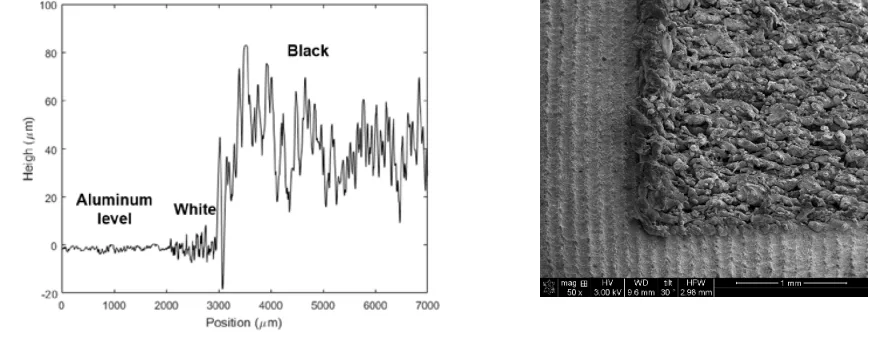
- Figure 2a and 2b - Left: Results from a surface profiler. The surface without treatment is represented before 2000 μm. Between 2000 µm and 3000 µm is a whitened surface. After 3000 µm, a blackened surface was generated. Right: SEM image of the black and white.
- Figure 3: Schema of the geometrical protection of the black marking by a cell smaller than the blast media.
- Figure 4: Experimental setup for laser marking on an aluminium component.
- Figure 5: Viking Blast model: CB-3614.
- Figure 6: Close-up of a small-cell DMC before and after the shotblast treatment.
- Figure 7: Close-up of an 100% filled DMC post-shotblast
- Figure 8: DMC with varying fillings (30%, 55% and 100% respectively).
- Figure 9: A close-up of a 80% filled 2D matrix. So is the size of the module.
- Figure 10: Close-ups of an 100% filled DMC (left) and a 80% filled DMC (right). The cell size (Sc) is 1 mm.
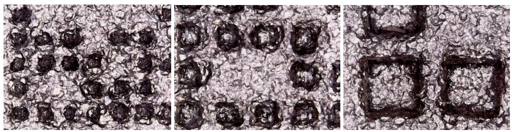
- Figure 11: DMC with varying size: From left to right, 0.3 mm, 0.55 mm and 1.6 mm cell size, respectively)
- Figure 12: Wheelabrator model: Tumblast
- Figure 13: DMCs with cell sizes ranging from 0.3 mm to 0.55 mm before and after the shotblast procedure.
- Figure 14: DMCs with cell sizes ranging from 0.85 mm to 0.95 mm before and after the shotblast procedure.
- Figure 15: Evolution of contrast in relationship with cell size.
- Figure 16: Evolution of contrast in relation with depths for all readable DMCs.
- Figure 17: Evolution of contrast in relationship with time for the five different depths.
- Figure 18: Evolution of contrast in relationship with time of marking with emphasis on first two laser passes. The squares represent the depth of 0.15mm while the circles represent the depth of 0.30mm.
- Figure 19: Geometric interpretation of a cast steel ball interacting with the bottom of a cell.
- Figure 20: Top view of a cell before and after the shotblast treatment.
- Figure 21: Three DMCs (from left to right Sc= 0.5 mm, Sc= 0.75 mm, Sc= 1.6 mm) taken at a depth of 0.60 mm
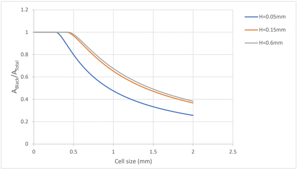
- Figure 22: Graphs of the relation between the black area ratio and depths for cell sizes ranging from 0.6 mm to 1.6 mm.
- Figure 23: Graphs of the relation between the black area ratio for cell depths of 0.05 mm, 0.15 mm and 0.6 mm.
- Figure 24 :Marking full of carbon steel shots
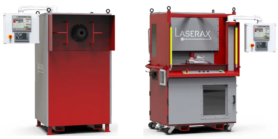
- Figure 25: Left: Open Air enclosure, Right: Rotary Table enclosure
7. Conclusion:
Laser marking is the most viable technology for permanent traceability markings. The challenges of creating shot-blast resistant marks within a short cycle time can be addressed by the Laserax LXQ-100 system. For DMCs with low data capacity (e.g., six numerical characters), marking times under 10 seconds are achievable while maintaining a high grade (B or better per ISO 29158). Higher-capacity DMCs can also achieve high grades post-shotblast within reasonable timeframes. The paper explains which type of enclosure (Open Air or Turntable) is suitable depending on data and cycle time requirements. These breakthroughs allow diecasters to confidently implement in-line laser marking solutions, even for parts that undergo subsequent shotblasting.
8. References:
- Maltais, J., Brochu, V., Frayssinous, C., Vallée, R., Godmaire, X., Fraser, A. “Surface analysis study of laser marking of aluminium,” ICSCOBA 2016
Expert Q&A: Your Top Questions Answered
Q1: Why was the initial hypothesis of using cells smaller than the shot media incorrect?
A1: The initial hypothesis failed because it did not account for the material properties of the workpiece. As stated in the analysis, aluminum is a soft and ductile material. When impacted by the much harder steel shot, the aluminum surface deformed and flowed, effectively "clogging" the small holes and destroying the code's readability, as visually documented in Figure 6.
Q2: What is the "cell filling ratio" and why is it so critical for shotblast resistance?
A2: The "cell filling ratio" is the concept of not engraving the entire area of a black cell in the data matrix. For example, an 80% filling ratio means a smaller square is engraved within the cell's boundary, leaving a 20% wide "wall" of original material around it. This wall is critical because it acts as a protective barrier, absorbing the energy from the shotblast media and preventing the marked surface inside from being flattened, thus preserving the code's contrast as shown in Figure 10.
Q3: What is the optimal range for cell size, and what are the consequences of going outside this range?
A3: The study identified an optimal cell size range between 0.55 mm and 0.95 mm. As shown in the results (Table 2 and Figure 15), cell sizes below 0.5 mm are too small and get clogged by material deformation during shotblasting, resulting in an unreadable "F" grade. Cell sizes above 0.95 mm begin to show a decrease in contrast, as the larger open surface is more susceptible to being hit and damaged by the shot media.
Q4: How important is the marking depth for the final quality of the code after shotblasting?
A4: While depth is a factor, the results showed it was less critical than cell size and filling ratio, provided a certain minimum was achieved. The geometric analysis in Figure 19 suggests that a depth greater than half the shot's diameter (D/2, or approximately 0.215 mm for the S170 shot used) is sufficient to geometrically protect the center of the cell floor. The data in Figure 16 shows that for optimal cell sizes (0.55mm to 0.90mm), contrast is only slightly affected by changes in depth.
Q5: Is it possible to achieve a readable, high-grade mark within a typical die casting cycle time?
A5: Yes, absolutely. The study concludes that for a 10x10 DMC (capable of encoding 6 numerical characters), a shot-blast resistant mark can be created in less than 10 seconds. As shown in Figure 18 and the accompanying analysis, using just two laser passes (for a depth of approx. 0.30 mm) yields a high-contrast code with a high overall quality grade (A or B), which is well within typical manufacturing cycle times.
Q6: What is the main trade-off when choosing between an Open Air and a Rotary Table enclosure for inline integration?
A6: The main trade-off is between cost/footprint and hidden processing time. According to Table 4, the Open Air enclosure has a lower cost and a smaller footprint, but the marking time is part of the overall cycle time. The Rotary Table enclosure is more expensive and larger, but it allows the marking to happen on a part while the next part is being cast ("hidden time"), which enables the use of lower power lasers or the creation of deeper marks without impacting overall throughput.
Conclusion: Paving the Way for Higher Quality and Productivity
The inability to maintain part traceability through post-processing has long been a barrier to achieving true process control in die casting. This research provides a definitive breakthrough, establishing a clear, data-backed methodology for Shotblast Resistant Laser Marking. By optimizing cell size, depth, and a novel filling ratio, die-casters can now implement a robust marking solution directly in the casting cell, confident that the mark will survive even the most aggressive surface treatments. This enables complete, error-proof traceability, paving the way for enhanced quality control and process optimization.
At CASTMAN, we are committed to applying the latest industry research to help our customers achieve higher productivity and quality. If the challenges discussed in this paper align with your operational goals, contact our engineering team to explore how these principles can be implemented in your components.
Copyright Information
This content is a summary and analysis based on the paper "Inline Integration of Shotblast Resistant Laser Marking in a Die Cast Cell" by "J. Landry¹, J. Maltais¹, J-M. Deschênes¹, M. Petro², X. Godmaire¹, A. Fraser¹".
Source: NADCA 2018 Die Casting Congress & Exposition
This material is for informational purposes only. Unauthorized commercial use is prohibited.
Copyright © 2025 CASTMAN. All rights reserved.