This technical summary is based on the academic paper "Characterizing Flow Losses Occurring in Air Vents and Ejector Pins in High Pressure Die Castings" published by M.C. Carter, S. Palit, and M. Littler in NADCA (2010). It was analyzed and summarized for HPDC experts by CASTMAN experts with the help of LLM AI such as Gemini, ChatGPT, and Grok.
Keywords
- Primary Keyword: HPDC venting simulation
- Secondary Keywords: Flow loss coefficient, FLOW-3D simulation, Gas porosity reduction, Ejector pin venting, Die casting defects, Adiabatic bubble model, Computational Fluid Dynamics (CFD)
Executive Summary
- The Challenge: Accurately predicting and controlling air entrapment and resulting porosity in HPDC is a major challenge, as flow losses through vents, ejector pins, and other leak paths are difficult to quantify with simple calculations.
- The Method: Researchers combined physical "dry run" injection experiments on a commercial die with Computational Fluid Dynamics (CFD) simulations using FLOW-3D® software. They measured real-world cavity pressure changes and used this data to calibrate flow loss coefficients in the simulation.
- The Key Breakthrough: The study successfully demonstrated that CFD models—specifically the adiabatic bubble and valve models in FLOW-3D®—can be calibrated to accurately replicate the cumulative flow losses from vents, ejector pins, and residual die leaks.
- The Bottom Line: This provides a powerful, validated method for engineers to simulate, analyze, and optimize their venting strategies before production, leading to a significant reduction in gas porosity and higher quality parts.
The Challenge: Why This Research Matters for HPDC Professionals
For decades, engineers have grappled with surface defects and internal porosity in high-pressure die castings. These flaws, which compromise mechanical properties like yield strength and ductility, are primarily caused by entrapped air and gases from lubricant decomposition. While vacuum systems offer a solution, they are expensive and add complexity to the process.
As stated in the paper's introduction, venting remains the "easiest and least expensive method" to eliminate entrapped air. However, designing an effective venting system is far from simple. The total amount of venting is a complex sum of flow through dedicated vents, the shot sleeve, ejector pins, and the parting line. Without a reliable way to characterize these flow losses, engineers often rely on experience and trial-and-error, leading to costly tooling adjustments and inconsistent part quality. This research tackles this fundamental problem head-on by seeking a practical and accurate method to model these critical flow losses.
The Approach: Unpacking the Methodology
To solve this challenge, the researchers devised a clever methodology combining physical experiments with advanced simulation. They performed a series of injection experiments without molten metal ("dry runs") on a commercial die for a motor end head at Littler DieCast.
The core of the experiment involved:
- Isolating Variables: Running the die in various configurations: all vents open, vacuum valve closed, parting line sealed, ejector pins sealed, and all vents sealed.
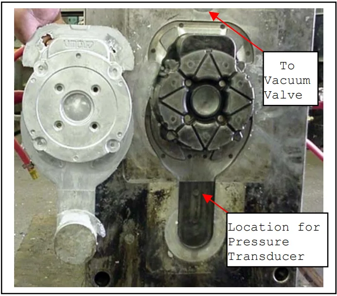
- Data Collection: Placing a pressure transducer inside the die cavity to precisely measure the pressure increase as a function of time for each configuration (Figure 3).
- CFD Simulation: Replicating these "dry run" scenarios using the commercial CFD software, FLOW-3D®. The key was the use of the software's adiabatic bubble model to represent the air in the cavity and its valve model to represent the flow losses through different orifices.
- Calibration: The ultimate goal was to adjust the "cumulative loss coefficient" in the simulation until the simulated pressure curves perfectly matched the real-world experimental data. This process effectively calibrates the simulation, making it a reliable digital twin of the actual die's venting performance.
The Breakthrough: Key Findings & Data
The study yielded several crucial insights that directly impact how we should think about venting in HPDC.
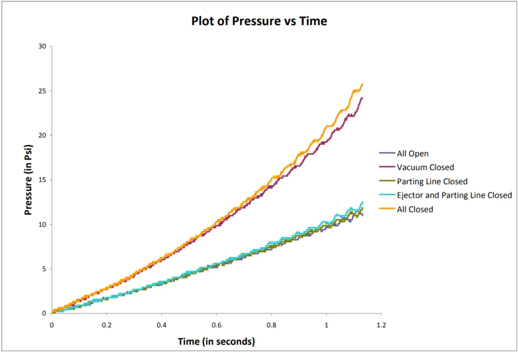
- Finding 1: Venting Sources Quantified: The experimental pressure curves in Figure 3 clearly showed the relative importance of each venting path. The largest pressure increase occurred when the vacuum valve was closed, identifying it as the primary source of venting. The smaller, but still significant, pressure drop caused by unsealed ejector pins (a drop of less than 2 Psi) was also quantified. Conversely, the parting line was found to be well-sealed, as its closure had an insignificant effect on cavity pressure.
- Finding 2: The Critical Role of Residual Leaks: A major revelation came from comparing the "All Closed" experimental run with a purely theoretical simulation. While the simulation predicted a final pressure of 169 psi (Figure 5), the actual experiment only reached about 25 psi (Figure 3). This massive 144 psi difference points to significant "residual leakages" through paths like the shot sleeve, which are often overlooked but clearly play a major role in air evacuation.
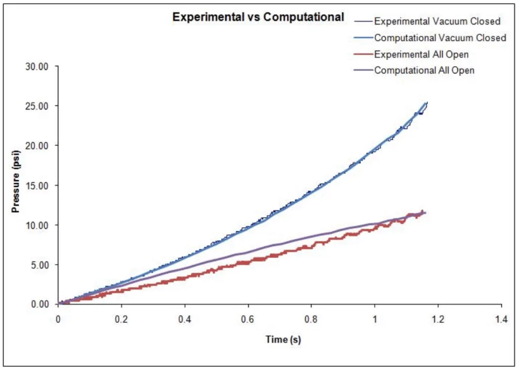
- Finding 3: Simulation Accuracy Validated: The research successfully demonstrated that the calibrated FLOW-3D® model could accurately replicate the experimental results. As shown in Figure 6, the computational pressure curves for both the "Vacuum Closed" and "All Open" cases show excellent agreement with the measured experimental data, validating this as a reliable engineering tool.
- Finding 4: Specific Loss Coefficients Determined: Through the calibration process, the researchers calculated precise cumulative loss coefficients. For the "Vacuum Closed" scenario (venting through ejector pins and residual leaks), the coefficient was 3.73e-6 m²/√(kg/m³). For the "All Open" scenario (all venting paths combined), it was 6.4e-6 m²/√(kg/m³). These values represent a powerful data point for future simulation work.
Practical Implications for HPDC Products
- For Process Engineers: The paper's methodology offers a way to move beyond guesswork. By quantifying the venting contribution of each die element (as detailed in the "RESULTS AND DISCUSSION" section), you can more precisely optimize shot profiles and intensification pressure to ensure complete air evacuation without resorting to excessive trial-and-error.
- For Quality Control: The significant gap between theoretical and actual "All Closed" pressure (Figure 3 vs. Figure 5) highlights that residual leaks are a major, measurable factor. This suggests a simple dry-run pressure test could be implemented as a powerful QC check to assess die wear or seal integrity, predicting potential porosity issues before a single part is cast in metal.
- For Die Design: This research validates that using a tool like FLOW-3D® allows designers to digitally test and confirm the effectiveness of their venting and overflow designs before cutting steel. By assigning a calibrated loss coefficient, as demonstrated in the study, you can simulate whether a proposed design provides adequate venting, preventing costly tooling rework and dramatically reducing the learning curve on new dies.
Paper Details
Characterizing Flow Losses Occurring in Air Vents and Ejector Pins in High Pressure Die Castings
1. Overview:
- Title: Characterizing Flow Losses Occurring in Air Vents and Ejector Pins in High Pressure Die Castings
- Author: M.C. Carter, S. Palit, M. Littler
- Year of publication: 2010
- Journal/academic society of publication: NADCA (North American Die Casting Association)
- Keywords: HPDC, venting, flow loss, porosity, computational fluid dynamics, FLOW-3D, ejector pins, adiabatic bubble model
2. Abstract:
It will be demonstrated how the commercial computational fluid dynamics (CFD) software, FLOW-3D®, can be used to model the flow losses occurring in ejector pins and air vents in high pressure die castings. The results from an ejection experiment done without melt at a commercial tool shop will be discussed. These results will then be used to compute flow loss coefficients for the air vents, ejector pins and residual leaks with the help of the adiabatic bubble model in FLOW-3D®. We will explore an effective tool for calibrating the losses that occur during a pressurized fill in high pressure die castings.
3. Introduction:
Surface defects reduce thermal and mechanical properties such as yield strength, ductility and modulus of elasticity of parts produced in high pressure die casting. The surface defects occur due to air entrapment and/or solidification shrinkage. Entrapped gases during fill and the gases evolved during decomposition of lubricants, cause porosity. Vacuum die casting can eliminate these gases. Vacuum valves are expensive and there is a possibility of destroying the valve and/or pump if the valve is not closed before the metal leaves the shot sleeve. Moreover, an additional runner system needs to be adequately designed so that effective cooling and solidification occurs preventing the metal from entering the vacuum valve. If no vacuum is used then adequate venting along with proper gating and runner design can eliminate gas porosity. Venting helps eliminate entrapped air by allowing the gas to have an outlet during the fill. Venting is the easiest and least expensive method to use. The amount of venting through the sleeve, ejector pins, parting line, and vacuum valves are considered while designing vents.
4. Summary of the study:
Background of the research topic:
Air entrapment during high-pressure die casting causes porosity, which degrades the mechanical properties of the final product. Venting is the most common and cost-effective method to remove this air, but it is difficult to design effective venting systems without a clear understanding of the flow losses through various orifices in the die.
Status of previous research:
Prior attempts to model flow losses have used methods like the Darcy-friction factor and Moody's diagram, which can be complex and may not fully capture the dynamics in a die casting environment.
Purpose of the study:
This study aimed to demonstrate a practical and effective method using commercial CFD software (FLOW-3D®) to model and calibrate the cumulative flow losses from air vents, ejector pins, and residual leaks in an HPDC die.
Core study:
The core of the study involved conducting physical "dry run" injection experiments on a commercial die under various venting conditions. The pressure inside the cavity was measured and used as a benchmark to calibrate a CFD simulation. By matching the simulated pressure curves to the experimental data, the researchers could determine accurate cumulative loss coefficients for the entire venting system.
5. Research Methodology
Research Design:
The study employed a comparative research design, benchmarking CFD simulation results against physical experimental data. Injection experiments were performed without melt on a motor end head die. The experimental configurations included: all open, vacuum closed, parting line closed, ejector and parting line closed, and all closed.
Data Collection and Analysis Methods:
A pressure transducer was installed in the die to record pressure as a function of time for each experimental run. These pressure curves were then compared to simulation outputs from FLOW-3D®. The software's valve model was calibrated by adjusting the cumulative loss coefficient until the computational results showed good agreement with the experimental data.
Research Topics and Scope:
The research focused on characterizing air flow losses in a high-pressure die casting tooling. The scope included losses through a vacuum valve, 26 ejector pins, the parting line, and other residual leaks. The study used FLOW-3D®'s adiabatic bubble model and valve model to perform the simulations.
6. Key Results:
Key Results:
- Experimental data showed the vacuum valve was the primary venting path, followed by the ejector pins. Parting line leakage was negligible.
- A significant residual leak was identified, evidenced by the large discrepancy between the theoretical "All Closed" pressure (169 psi) and the measured experimental pressure (~25 psi).
- The FLOW-3D® simulation, using the adiabatic bubble model, showed excellent agreement with experimental pressure curves once calibrated.
- Specific cumulative loss coefficients were calculated: 3.73e-6 m²/√(kg/m³) for the "Vacuum Closed" case and 6.4e-6 m²/√(kg/m³) for the "All Open" case.
Figure Name List:
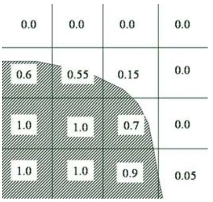
- Figure 1: Typical values of the VOF function near a moving metal front.
- Figure 2: The cast part (end head of motor) and the die.
- Figure 3: Experimental results of pressure (in Psi) plotted against time (in sec) for the dry runs.
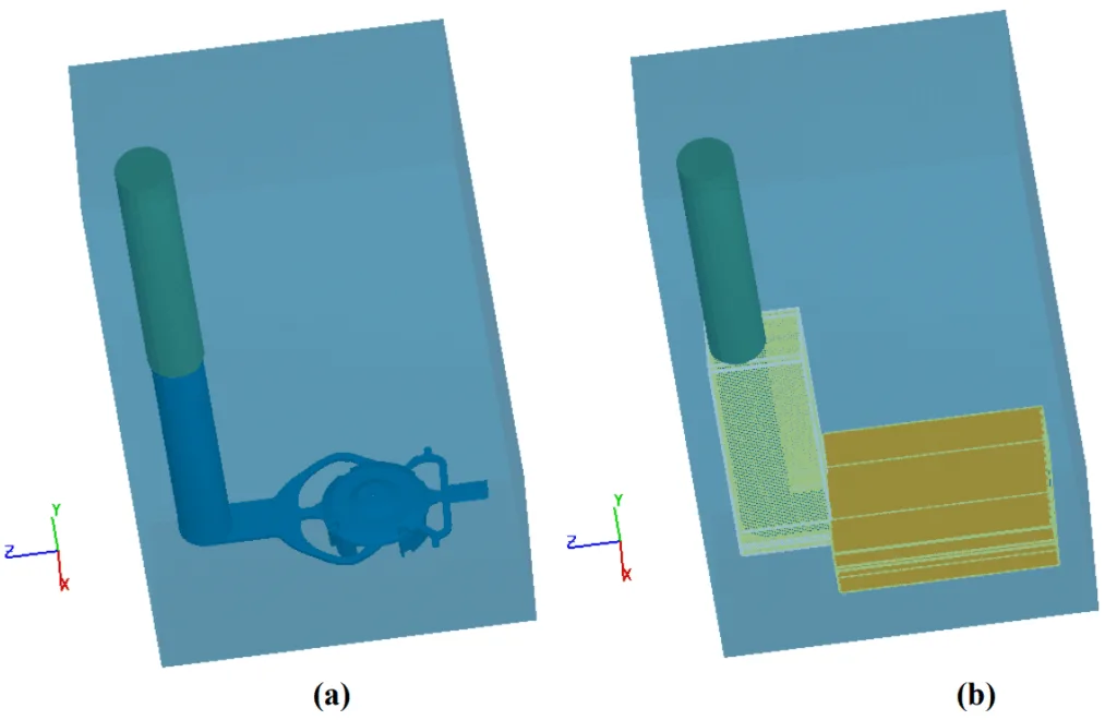
- Figure 4: A snapshot of the geometry (a) without mesh and (b) with computational mesh.
- Figure 5: Pressure curves from the "All Closed" for 1-compressible and 2-adiabatic simulations.
- Figure 6: Comparison of experimental and computational results.
7. Conclusion:
Many authors have tried to model the flow losses at vents using the Darcy-friction factor and Moody’s diagram and Fanno flows where compressibility effects are taken into account. We have shown that these losses can be modeled through the use of simple adiabatic bubble and valve models in FLOW-3D®. In future this model needs to be used in conjunction with an actual metal fill in order to study the porosity in the part due to improper venting. The valve model also needs to be used in a broader framework which looks at compressible flow losses occurring at vents under certain conditions as well as the effect of different geometries, and gas densities on the cumulative loss coefficient.
8. References:
- [1] White, F.M., Fluid Mechanics, 4th ed., p 256, John Fellows Publishing Co., New York, NY (1940)
- [2] Flow of Fluids Through Valves, Fittings, and Pipe, Crane Technical Paper No. 410, Joliet, IL: Crane Co., 1988.
- [3] C.W. Hirt and B.D. Nichols, “Volume-of-Fluid (VOF) Method for the Dynamics of. Free Boundaries,” J. Comp. Phys., 39, 1981, pp. 201-225.
- [4] FLOW-3D® v 9.4 Manual
- [5] Mold Filling Simulation of High Pressure Die Casting for Predicting Gas Porosity, Modeling of Casting, Welding, and Advanced Solidification Processes X, TMS (The Mineral, Metals, & Materials Society), 2003, pp. 335
- [6] Modeling of Air Venting in Pressure Die Casting Process, Nouri-Borujerdi, A., Goldak, J.A., AD, Journal of Manufacturing and Science and Engineering, ASME, 2004
Expert Q&A: Your Top Questions Answered
Q1: Why is accurately modeling flow loss so important in HPDC?
A1: Accurately modeling flow loss is critical because uncontrolled air entrapment is a primary cause of gas porosity. As stated in the paper's introduction, porosity degrades essential mechanical properties like yield strength and ductility, leading to failed parts and increased scrap.
Q2: My vents seem correctly designed, but I still get gas porosity. What could be the cause?
A2: This research highlights that "residual leaks," such as those through the shot sleeve, can be a very significant, yet often overlooked, factor in venting. The study found a pressure difference of over 140 psi between theory and reality in a fully closed die, proving that these leaks are substantial. Your issue may lie in these unquantified leak paths rather than your primary vents (Comparison of Figure 3 and Figure 5).
Q3: Is it possible to quantify how much venting I get from my ejector pins versus a dedicated vent?
A3: Yes. The methodology in this paper provides a clear template. By conducting sequential "dry runs" where you close off one venting system at a time (e.g., run 1: all open; run 2: dedicated vent closed), you can use a pressure transducer to measure the change in the pressure curve, as was done in Figure 3. This allows you to isolate and quantify the venting effectiveness of each component.
Q4: What is the "adiabatic bubble model" and why is it useful?
A4: The adiabatic bubble model is a feature in FLOW-3D® that simplifies the complex physics of a compressible gas into a highly efficient and accurate calculation. As Figure 5 shows, its results were in "excellent agreement" with a more complex compressible gas simulation. This makes it a powerful and practical tool for accurately calculating pressure buildup in the die cavity during a filling simulation.
Q5: How can simulation help me optimize my venting design before I cut steel for a new die?
A5: This study demonstrates that by calibrating a CFD model, you can determine a single "cumulative loss coefficient" that represents your entire die's venting system. As discussed in the paper's conclusion, this allows you to use a tool like FLOW-3D® to digitally test and compare different vent sizes, overflow designs, and locations to ensure adequate air evacuation before manufacturing the tool, saving significant time and cost.
Q6: What were the key numerical results from this study that I can use as a reference?
A6: The study produced two key calibrated values. The cumulative loss coefficient for venting through ejector pins and residual leaks only ("Vacuum Closed") was 3.73e-6 m²/√(kg/m³). The coefficient for the entire system venting together ("All Open") was 6.4e-6 m²/√(kg/m³). These were derived by matching the simulation to real-world data, as shown in Figure 6.
Conclusion & Next Steps
This research provides a valuable roadmap for moving beyond intuition in HPDC vent design. By combining targeted physical experiments with calibrated CFD simulations, it's possible to quantify and optimize the complex network of air flow paths in a die. The findings offer a clear, data-driven path toward improving part quality, reducing porosity-related defects, and optimizing production from day one.
At CASTMAN, we are dedicated to applying the latest industry research to solve our customers' most challenging die casting problems. If the issues discussed in this paper resonate with your operational goals, contact our engineering team to discuss how we can help you implement these advanced principles in your components.
Copyright
- This material is a paper by "M.C. Carter, S. Palit, and M. Littler". Based on "Characterizing Flow Losses Occurring in Air Vents and Ejector Pins in High Pressure Die Castings".
- Source of the paper: NADCA CastExpo'10 Conference Proceedings.
This material is for informational purposes only. Unauthorized commercial use is prohibited. Copyright © 2025 CASTMAN. All rights reserved.