by Byung-Lip Ahn 1,2,Ji-Woo Park 1,Seunghwan Yoo 1,Jonghun Kim 1,Seung-Bok Leigh 2 andCheol-Yong Jang 1,*
Abstract
Light-emitting diode (LED) lighting should be considered for lighting efficiency enhancement, however, waste heat from light-emitting diode (LED) lighting increases the internal cooling load during the summer season. In order to solve this problem we propose a thermal management system for light-emitting diode (LED) lighting with a heat exchanger module integrated with the building’s heating, ventilation, and air conditioning (HVAC) system to move the lighting’s waste heat outdoors. An experiment was carried out to investigate the thermal effects in a test chamber and the heat exchange rate between the heat sink and the duct air. The heat generated by the light-emitting diode (LED) lighting was calculated as 78.1% of light-emitting diode (LED) input power and the heat exchange rate of the lighting heat exchange module was estimated to be between 86.5% and 98.1% according to the light-emitting diode (LED) input power and the flow rate of air passing the heat sink. As a result, the average light-emitting diode (LED) lighting heat contribution rate for internal heat gain was determined as 0.05; this value was used to calculate the heating and cooling energy demand of the office building through an energy simulation program. In the simulation results, the cooling energy demand was reduced by 19.2% compared with the case of conventionally installed light-emitting diode (LED) lighting.
Keywords:
light-emitting diode (LED); lighting heat; thermal management; cooling energy demand
1. Introduction
Light-emitting diodes (LEDs) have become widely available in various industrial fields concerned with energy saving and offer positive environmental effects due to their advantages over conventional light sources, such as low power consumption, long lifetime, rapid response time, compact physical size, and physical robustness [1,2,3]. In particular, in order to reduce indoor lighting energy use, which accounts for nearly 30% of the total energy use in buildings, high-efficiency LED lighting and daylight dimming control technologies have been developed [4,5,6]. High-efficiency LEDs convert nearly 15%–25% of electric power to visible light, while the rest is transformed into heat. If the heat generated by an LED device cannot be effectively removed, LED performance becomes unstable and suffers, for instance, lower light conversion efficiency, a change of color, and decreased lifetime [7,8]. Therefore, thermal management and control of the junction temperature of LEDs has become a crucial research area in the overall development of high-power and high-efficiency LEDs.
Thermal management systems for enhancing the efficiency of LED lighting should be considered from the chip level to the system level, involving optimum chip design with a patterned sapphire substrate, structures for a direct thermal path to the heat sink, and a cooling method with a fan or thermoelectric cooler to dissipate heat to the surroundings [9,10,11,12,13]. Among these aspects, the associated heat sink must be considered and optimized for reliable cooling performance in high-power LED lighting. Numerous researchers have analyzed natural- and forced-convection heat sinks with diverse fin configurations in rectangular and radial shapes and heat pipe connections. The natural-convection type is preferred on account of needing no additional fans or electric consumption, even though natural-convection heat sinks are thermally less effective, being consequently less compact and heavier than forced-convection types, and require careful design to achieve the required thermal performance [14,15,16,17].
In terms of building environment, the waste heat from the heat sink generally stays within the ceiling and can be transferred into an indoor space as a form of convective heat transfer that increases indoor air temperature and cooling load during the summer season [18,19,20,21]. To prevent this negative effect on energy demand during the cooling period in buildings, Ahn et al. [22] suggested a movable heat sink for LED lighting connected with the heating, ventilation, and air conditioning (HVAC) ductwork in an office building to remove heat to the outdoors during the cooling period and to fully reuse the heat indoors during the heating period. In that research, a cooling and heating energy saving of 9.3% was obtained in the computational simulation result compared with conventional lighting fixtures in an office building. However, the research involved only conceptual design for lighting heat control and simulated verification, and neither experimental implementation nor verification.
In this study, therefore, we propose an alternative system of LED lighting integrated with a heat exchange module and HVAC duct, and carried out a systematic experimental study to investigate thermal effects in the test chamber with a manufactured prototype. The total energy savings in heating and cooling of an office building were calculated through an energy simulation program using the experimental results to evaluate the effectiveness of our proposed method.
2. Methodology
2.1. LED Lighting Thermal Management System
In a thermal network model for the high-power LED device applied in this study, heat dissipated from the LED is transferred to a PCB and through heat pipes and a cooling device (heat sink) to reject heat to the surroundings as shown in Figure 1. The thermal resistances from the LED diodes to the ambient surroundings are related in the following equation [23,24]:
��,�=��−���ℎ���=��−����+���−ℎ�+�ℎ�−ℎ��+����−��+�ℎ�−�(1)
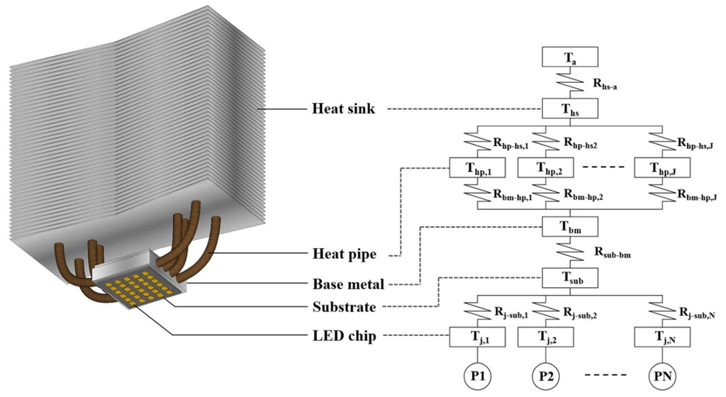
Figure 1. Illustration of LED lighting application and thermal network model.
This heat dissipated from the heat sink to the ambient background is transferred to the conditioned space in the building, affecting the internal thermal condition, and increasing the cooling load in the summer season.
As shown in Figure 2, we designed an alternative thermal management system with an LED lighting heat exchange module (LHEM) capable of reducing the internal heat gain in an indoor space by transferring LED lighting heat to the outdoors using the HVAC system. In this system, the dissipated heat from the LED is transferred to the heat sink located in the module via a connected heat pipe; this heat is exchanged by air flow from the HVAC fan. The heated air passing the heat sink is moved outdoors through the exhaust duct to reduce cooling load during the cooling period and is returned to the internal space during a heating period to increase internal heat gain, depending on the seasonal operating scheme.
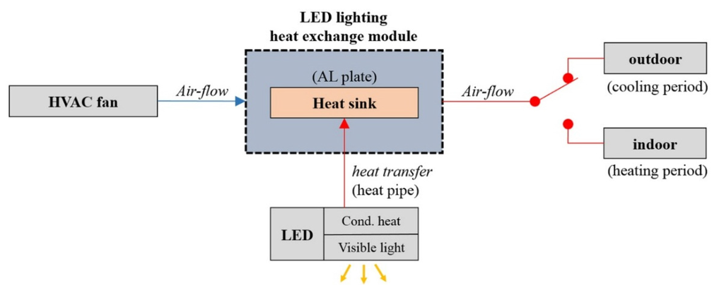
Figure 2. Schematic view of an alternative thermal management system with an LED lighting heat exchange module (LHEM).
2.2. Experimental System and Theoretical Method
Figure 3 presents an operational illustration of the thermal management system with the LHEM for the experimental test. A baseline test without the heat exchange module was conducted to determine the heat generated by the LED lighting under various input powers. Because the calculation of the heat generated by the LEDs is quite complex as derived in Equation (1), we assumed that the heat generated from lighting is approximately equal to the heat lost from the internal test chamber to the ambient environment in a steady state. Thus, the heat generated by LED lighting can be expressed as:
�ℎ���≅��(2)
��=����(���−��)(3)
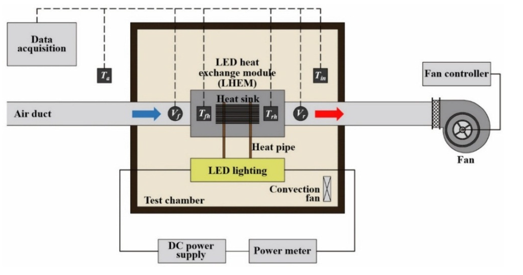
Figure 3. Operational illustration of the thermal management system with the LHEM.
In the LHEM system, owing to heat removal through the supply air passing to the outdoors across the heat sink, the total heat generation from LED lighting can be calculated by combining the heat loss and heat removal values at the steady state. The heat generated by LEDs is given by the following equations:
�ℎ���≅��+��(4)
��=�����(��ℎ−��ℎ)(5)
2.3. Experimental Setup
The major equipment items include a small-scale test chamber, an LED lighting system with a heat exchange module, a fan connected with the air duct, and a monitoring and control system. The test chamber consisted of EPS insulation (50 mm) and plywood (9 mm), and the inner space was 0.8 m wide, 0.8 m long, and 0.8 m high. In the LED lighting system, a chip-on-board (COB) packaged LED, which was 40 mm in width and 40 mm in length, was used to enhance heat transfer efficiency because of high heat flux in a small area [25,26]. The luminous flux of the LED was 5800 lm with 5700 K color temperature, and more than 95 lm/W in luminous efficiency at the 60 W output power. The heat pipe attached to the back side of the LED consisted of copper, with water as the working fluid [15]. The aluminum-plate heat sink was connected to the heat pipe and was located in the heat exchange module to cool the device by dissipating heat by air flow. To provide air flow in the module, the fan was connected with a spiral duct 150 mm in diameter. An Agilent data logger was used for monitoring the air temperature of the inner space of the test chamber, the inlet and outlet of the heat exchange module, and the ambient environment by using thermocouples in one-minute intervals. The air flow rate in the duct was calculated based on air velocity measured at the outlet/inlet of the heat exchanger module by a Kanomax 6035 anemometer. In order to ensure uniform distribution of the internal air temperature, a convection fan was installed in the test chamber.
For comparison, indoor thermal effects were examined under various LED lighting input powers (40‒80 W) supplied by a CEN-100-36 (Meanwell, Taiwan) adjustable-current DC power supply. Because the air flow rate from the HVAC fan is determined based on the ventilation rate for different space types [27], it is necessary to estimate the heat exchange rate of the LHEM system on various air flow rates. Thus, the fan operation speed was controlled in three steps, 1, 3 and 5 m/s, where the duct diameter was 150 mm. The calculated air flow rate through the air duct was 60 cubic meters per hour (CMH), 180 CMH, 300 CMH, respectively. The equipment and temperature sensors for the baseline and LHEM test are shown in Figure 4a,b, respectively, and the overall view of the test chamber with the LHEM system is shown in Figure 4c.
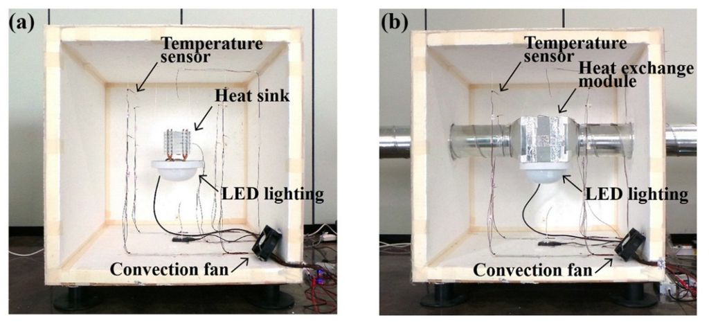
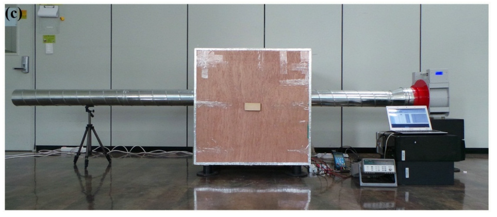
Figure 4. The equipment and temperature sensors for (a) the baseline test; (b) the LHEM test; and (c) the overall view of the test chamber with the LHEM system.
3. Results and Discussion
3.1. Experimental Results
This section describes measurement results when the ambient temperatures of the each case were quite similar: close to 21 °C on average. Because the ambient temperature was not constant, the baseline test was carried out three times at the same conditions, and the LHEM test was also carried out three times at 60, 180 and 300 CMH in terms of air flow rate. LED lighting was turned on ten minutes after the initial state was monitored.
The internal temperatures for LED powers of 40, 60 and 80 W in the baseline test and LHEM test were monitored as shown in Figure 5a. The average internal temperatures in the baseline test of each case increased by 10.2, 15.5 and 21.3 °C at the steady state when 40, 60 and 80 W of electric power was supplied to the LED lighting, respectively. On the other hand, in the LHEM test with the three cases of air flow rate, the average internal temperatures with LHEM system increased by 0.6, 1.1 and 1.4 °C at the steady state when 40 60 and 80 W of power was supplied, respectively. This indicates that the LHEM system removes a significantly greater amount of lighting heat from the LED device by air flow than in the baseline case, and has a cooling effect on the internal environment. The heat generated by the LED lighting, calculated through Equations (2) and (3), can be expected to form a regression line with 3.6% of standard error:
Pheat = 0.781PLED(6)
where ���� represents the electric power of the LED. Thus, the experimental result of the baseline test confirms that the LED lighting heat was emitted as nearly 80% of input power, as found in previous research.
In order to estimate the heat removed by the LHEM system; the air temperature difference between the front and rear sides of the heat sink in the module was monitored at 60, 180 and 300 CMH of air flow rate; as shown in Figure 5b. In the 40 W LED case with the LHEM system; the temperature difference was measured as 1.5, 0.4 and 0.3 °C at 60, 180 and 300 CMH; respectively. The heat removed in the 40 W LED case was calculated through Equation (5) as 27.0 W to 28.3 W. In the 60 W LED case; the temperature difference was measured as 2.3, 0.7 and 0.4 °C at 60, 180 and 300 CMH, respectively; and the heat removed was calculated as 42.5 W to 45.0 W. In addition; in the 80-W LED case; the temperature difference was measured as 3.2, 1.0 and 0.6 °C at each air flow rate; and the removed heat was calculated as 59.9 W to 61.3 W.
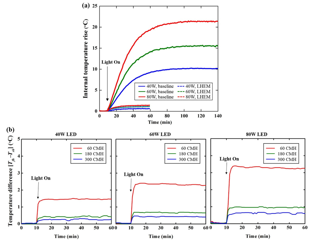
Figure 5. (a) Average internal temperature rise in the baseline and LHEM tests and (b) temperature difference between the front and rear sides of the heat sink with the LHEM.
Figure 6 shows the calculated result of the internal heat gain and removed heat according to the LHEM system using experimental data from 40 W to 80 W. Compared with the heat generated by the LED lighting and the heat removed by the LHEM system, in the 40 W LED case, the heat exchange ratio was calculated as 86.5% to 90.6%, according to the air flow rate. As a result, the internal heat gain from the LED lighting was 1.7 W when the LHEM system was operating, and the contribution rate of the LED power to internal heat gain was estimated as 4.3%. In the 60 W LED case, the heat exchange ratio was determined as 90.7% to 96.0% according to air flow rate, and the internal heat gain was 3.0 W, with a 5.1% contribution rate to internal heat gain. Finally, in the 80 W LED case, the heat exchange ratio was calculated as 95.9% to 98.1% according to the air flow rate, and the internal heat gain was 4.1 W, with a 5.1% contribution rate to internal heat gain.
Although there were differences in the result of the heat exchange ratio calculation, results showed that most LED heat could be removed by air flow, consequently reducing the internal heat gain of the test chamber. Table 1 compares the internal heat gain of the baseline and the LHEM tests and the contribution rate in each case.
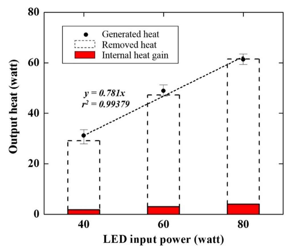
Figure 6. Output heat from the LED lighting with the LHEM system.
Table 1. Internal heat gain with and without the LHEM system.

3.2. Heating and Cooling Energy Savings in an Office Building
To investigate the energy-saving effect of an office building with the LHEM system, we estimated the heating and cooling energy demand of an office building at the Korea Institute of Energy Research in Daejeon, Republic of Korea, using the simulation program EnergyPlus [28]. The net floor area of the office building is 6164.8 m2 and the maximum height is 24.1 m, with five floors above ground and one underground. The building was designed to have a double skin on the south side and a central atrium to allow natural light in. However, daylight entering through the atrium is currently only used to light the hallways, so artificial lights are required in the perimeter zones for the recommended illuminance. The office building was modeled in 3D using the OpenStudio software provided by the National Renewable Energy Laboratory of the U.S. Department of Energy as shown in Figure 7.
The interior LED lighting was installed in the office building with a light power density (LPD) of 8.0 W/m2. The heat fractions of the lighting fixtures for EnergyPlus are listed in Table 2; these were determined by the contribution rates found in the experiment. In the baseline case, the heat fraction of visible light was 0.22 and the convective heat gain was 0.78. On the other hand, when the LHEM system was applied with the seasonal operating scheme, which is presented in Figure 2, the heat removal fraction was 0.73 during the cooling period and the convective heat gain was 0.78 during the heating period. To calculate the energy demand of the reference building, the “Ideal Loads Air System” of EnergyPlus was used. Occupancy, lights, heating and cooling schedules, and input parameters [29,30] for EnergyPlus are summarized in the Appendix at the end of this paper.
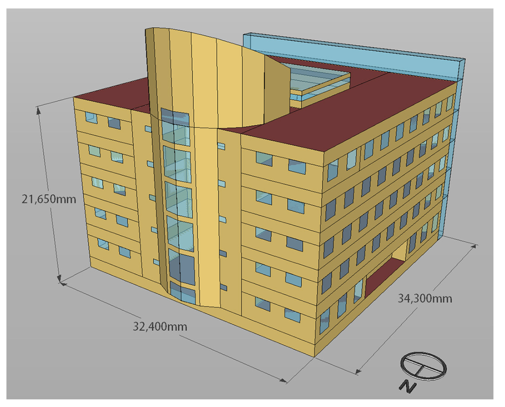
Figure 7. Illustration of the office building model.
Table 2. Lighting heat gain fractions for energy simulation estimation.

Figure 8 shows the simulation results for both cases. The annual energy demand of the office building without the LHEM system in the baseline case was calculated as 186.2 MWh for heating and 154.2 MWh for cooling. Compared with the baseline case, the cooling energy demand of the LHEM case decreased by 19.2%, from 154.2 MWh to 124.6 MWh, thanks to lighting heat removal during the cooling period. The annual energy (for heating and cooling) of the LHEM system case was reduced by 8.6% compared with the baseline case, from 340.5 MWh to 311.1 MWh, even though the heating energy demand was calculated equally during the heating period because the lighting heat gain fractions of both cases were set at the same value. Furthermore, LHEM required no additional fan power to exchange the lighting heat with the air flow in the HVAC ductwork because the LED heat could be nearly removed at the minimum ventilation rate for occupancy, as explained in Section 3.1.
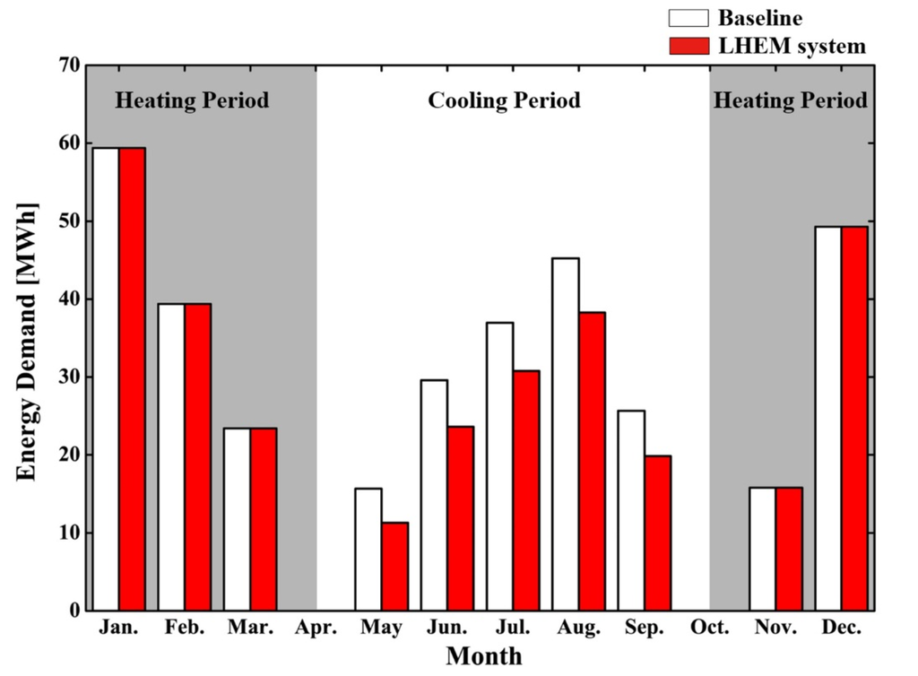
Figure 8. Heating and cooling energy demand for the model office building with and without the LHEM system.
4. Conclusions
LED lighting should be considered for its superior lighting conversion efficiency compared with conventional illumination. In terms of the building environment, however, waste heat from LED lighting can be transferred into indoor spaces by convective heat transfer, increasing the internal cooling load during the summer season. In order to prevent this adverse effect on cooling energy demand in buildings, we proposed a thermal management system for LED lighting integrated with a heat exchange module and HVAC ductwork to move lighting heat outdoors, and carried out a systematic experiment to investigate the heat exchange rate of the module and the cooling effect in a test chamber. In the experiment, the heat generated by the LED lighting was calculated as 78.1% of the supplied power to the LEDs, which ranged from 40 W to 80 W. The heat exchange rate of the LHEM module was estimated as 86.5% to 98.1% according to the LED input power and the air flow rate passing the heat sink at 60, 180 and 300 CMH. Based on these experimental results, we determined the average LED lighting heat contribution rate for internal heat gain as 0.05. The heating and cooling energy demand of the office building was calculated through an energy simulation program using this contribution rate. Simulation results show that cooling energy demand was reduced by 19.2% compared with the case of conventionally installed LED lighting. This indicates that the heat generated by LED lighting, which affects the internal cooling load, could be removed by using the LHEM system, furnishing cooling energy savings in the office building. However, because the lighting heat lost to the outdoors was not considered in this simulation study, there was no reduction in heating energy demand since the heat gain fraction during the heating period was equal in both test cases. We expect that the heat-reusing mode, which was not exploited in this study, could be effective in saving heating energy during the winter season; this can be evaluated by estimating the heat loss of the lighting heat through measuring the thermal conditions of the inner and plenum spaces in a real office building with conventionally installed lighting fixtures.
Acknowledgments
This work was supported by a National Research Foundation of Korea (NRF) grant funded by the Korean government (MSIP) (No. 2011-0028075).
Author Contributions
Cheol-Yong Jang provided guidance and supervision. Byung-lip Ahn implemented the main research, checked results, wrote the paper, and discussed the results. Ji-Woo Park and Seunghwan Yoo performed the experiment, Jonghun Kim designed the simulations, and Seung-Bok Leigh reviewed the paper. All authors read and approved the final manuscript.
Conflicts of Interest
The authors declare no conflict of interest.
Nomenclature
| �ℎ��� | heat generated by the LED, W |
| ��,� | thermal resistance from LED to ambient surroundings, K/W |
| ��−��� | thermal resistance from junction to substrate, K/W |
| ����−�� | thermal resistance from substrate to base metal, K/W |
| ���−ℎ� | thermal resistance from base metal to heat pipe, K/W |
| �ℎ�−ℎ� | thermal resistance from heat pipe to heat sink, K/W |
| �ℎ�−� | thermal resistance from heat sink to ambient surroundings, K/W |
| �� | junction temperature of the LED, K |
| ��� | internal air temperature, K |
| �� | ambient temperature, K |
| ��ℎ | air temperature at the front of heat sink, K |
| ��ℎ | air temperature at the rear of heat sink, K |
| � | number of LEDs |
| � | number of heat pipes |
| �� | heat lost from the internal test chamber to ambient surroundings, W |
| �� | heat removed by the air flow, W |
| �� | thermal transmittance of the envelopes, W/(m2K) |
| �� | surface area of the test chamber, m2 |
| �� | cross-sectional area of the air duct, m2 |
| ρ | air density, kg/m3 |
| � | specific heat of air, kJ/(kgK) |
| � | air velocity, m/s |
Appendix
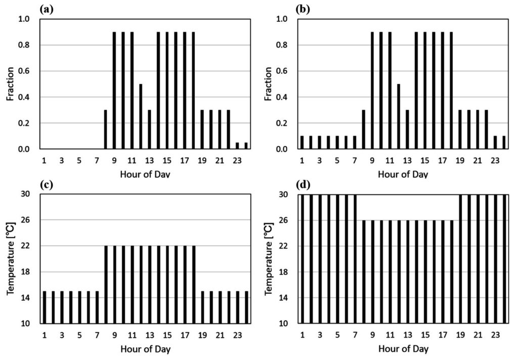
Figure A1. Hourly variations of internal loads following various schedules: (a) occupancy, and (b) indoor lights. The set temperatures for heating and cooling complied with the schedules: (c) heating and (d) cooling.
Table A1. Office building specifications, internal heat gains, thermal performance of the envelopes, ventilation and infiltration rates for EnergyPlus.

References
- Gutierrez-Escolar, A.; Castillo-Martinez, A.; Gomez-Pulido, J.M.; Gutierrez-Martinez, J.-M.; Stapic, Z.; Medina-Merodio, J.-A. A Study to Improve the Quality of Street Lighting in Spain. Energies 2015, 8, 976–994. [Google Scholar] [CrossRef]
- Han, J.-H.; Lim, Y.-C. Design of an LLC Resonant Converter for Driving Multiple LED Lights Using Current Balancing of Capacitor and Transformer. Energies 2015, 8, 2125–2144. [Google Scholar] [CrossRef]
- Weng, C.-J. Advanced thermal enhancement and management of LED packages. Int. Commun. Heat Mass Transf. 2009, 36, 245–248. [Google Scholar] [CrossRef]
- Yoon, Y.B.; Manandhar, R.; Lee, K.H. Comparative Study of Two Daylighting Analysis Methods with Regard to Window Orientation and Interior Wall Reflectance. Energies 2014, 7, 5825–5846. [Google Scholar] [CrossRef]
- Yoo, S.; Kim, J.; Jang, C.-Y.; Jeong, H. A sensor-less LED dimming system based on daylight harvesting with BIPV systems. Opt. Express 2014, 22, A132–A143. [Google Scholar] [CrossRef] [PubMed]
- Wermager, S.; Baur, S. Energy Analysis of a Student-Designed Solar House. Energies 2013, 6, 6373–6390. [Google Scholar] [CrossRef]
- Yung, K.C.; Liem, H.; Choy, H.S. Heat transfer analysis of a high-brightness LED array on PCB under different placement configurations. Int. Commun. Heat Mass Transf. 2014, 53, 79–86. [Google Scholar] [CrossRef]
- Yoon, Y.B.; Jeong, W.R.; Lee, K.H. Window Material Daylighting Performance Assessment Algorithm: Comparing Radiosity and Split-Flux Methods. Energies 2014, 7, 2362–2376. [Google Scholar] [CrossRef]
- Djavid, M.; Liu, X.; Mi, Z. Improvement of the light extraction efficiency of GaN-based LEDs using rolled-up nanotube arrays. Opt. Express 2014, 22, A1680–A1686. [Google Scholar] [CrossRef] [PubMed]
- Wei, T.; Huo, Z.; Zhang, Y.; Zheng, H.; Chen, Y.; Yang, J.; Hu, Q.; Duan, R.; Wang, J.; Zeng, Y.; et al. Efficiency enhancement of homoepitaxial InGaN/GaN light-emitting diodes on free-standing GaN substrate with double embedded SiO2 photonic crystals. Opt. Express 2014, 22, A1093–A1100. [Google Scholar] [CrossRef] [PubMed]
- Wang, J.-C. Thermal module design and analysis of a 230 W LED illumination lamp under three incline angles. Microelectron. J. 2014, 45, 416–423. [Google Scholar] [CrossRef]
- Chen, Y.; Sun, B.; Ma, T.; Sun, X. Thermal management for high-power photonic crystal light emitting diodes. Microelectron. Reliab. 2014, 54, 124–130. [Google Scholar] [CrossRef]
- Yung, K.C.; Liem, H.; Choy, H.S.; Cai, Z.X. Thermal investigation of a high brightness LED array package assemply for various placement algorithms. Appl. Therm. Eng. 2014, 63, 105–118. [Google Scholar] [CrossRef]
- Jang, D.; Kim, D.R.; Lee, K.-S. Correlation of cross-cut cylindrical heat sink to improve the orientation effect of LED light bulbs. Int. Commun. Heat Mass Transf. 2015, 84, 821–826. [Google Scholar] [CrossRef]
- Li, J.; Lin, F.; Wang, D.; Tian, W. A loop-heat-pipe heat sink with parallel condensers for high-power integrated LED chips. Appl. Therm. Eng. 2013, 56, 18–26. [Google Scholar] [CrossRef]
- Lu, X.; Hua, T.-C.; Wang, Y. Thermal analysis of high power LED package with heat pipe heat sink. Microelectron. J. 2011, 42, 1257–1262. [Google Scholar] [CrossRef]
- Shen, Q.; Sun, D.; Xu, Y.; Jin, T.; Zhao, X. Orientation effects on natural convection heat dissipation of rectangular fin heat sinks mounted on LEDs. Int. Commun. Heat Mass Transf. 2014, 75, 462–469. [Google Scholar] [CrossRef]
- Lam, J.C.; Tsang, C.L.; Yang, L. Impacts of lighting density on heating and cooling loads in different climates in China. Energy Convers. Manag. 2006, 47, 1942–1953. [Google Scholar] [CrossRef]
- Sezgen, O.; Koomey, J.G. Interactions between lighting and space conditioning energy use in US commercial buildings. Energy 2000, 25, 793–805. [Google Scholar] [CrossRef]
- Sezgen, O.; Koomey, J.G. Natural light controls and guides in buildings. Energy saving for electrical lighting, reduction of cooling load. Renew. Sustain. Energy Rev. 2015, 41, 1–13. [Google Scholar]
- Ahn, B.-L.; Jang, C.-Y.; Leigh, S.-B.; Jeong, H. Analysis of the Effect of Artificial Lighting on Heating and Cooling Energy in Commercial Buildings. Energy Procedia 2014, 61, 928–932. [Google Scholar] [CrossRef]
- Ahn, B.-L.; Jang, C.-Y.; Leigh, S.-B.; Yoo, S.; Jeong, H. Effect of LED lighting on the cooling heating loads in office buildings. Appl. Energy 2014, 113, 1484–1489. [Google Scholar] [CrossRef]
- Minseok, H.; Samuel, G. Development of a thermal resistance model for chip-on-board packaging of high power LED arrays. Microelectron. Reliab. 2012, 52, 836–844. [Google Scholar]
- Wang, J.-C. Superposition method to investigate the thermal performance of heat sink with embedded heat pipes. Int. Commun. Heat Mass Transf. 2009, 36, 686–692. [Google Scholar] [CrossRef]
- Wu, H.-H.; Lin, K.-H.; Lin, S.-T. A study on the heat dissipation of high power multi-chip COB LEDs. Microelectron. J. 2012, 43, 280–287. [Google Scholar] [CrossRef]
- He, F.; Chen, Q.; Liu, J.; Liu, J. Thermal analysis of COB array soldered on heat sink. Int. Commun. Heat Mass Transf. 2014, 59, 55–60. [Google Scholar] [CrossRef]
- American Society of Heating, Refrigerating and Air-Conditioning Engineers (ASHRAE), Inc. 2013 ASHRAE Handbook––Fundamentals, Ventilation and Infiltration, American Society of Heating; ASHRAE Inc.: Atlanta, GA, USA, 2013; pp. 16.27–16.28. [Google Scholar]
- Crawley, D.; Lawrie, L.; Winkelmann, F.; Buhl, W.F.; Huang, H.J.; Pedersen, C. EnergyPlus: Creating a new-generation building energy simulation program. Energy Build. 2001, 33, 319–331. [Google Scholar] [CrossRef]
- Deru, M.; Field, K.; Studer, D.; Benne, K.; Griffith, B.; Torcellini, P.; Liu, B.; Halverson, M.; Winiarski, D.; Rosenberg, M.; et al. U.S. Department of Energy Commercial Reference Building Models of the National Building Stock; National Renewable Energy Laboratory: Golden, CO, USA, 2011. [Google Scholar]
- American Society of Heating, Refrigerating and Air-Conditioning Engineers (ASHRAE), Inc. ASHRAE Standard 90.1 (2004),Energy Standard for Buildings except Low Rise Residential Buildings; ASHRAE Inc.: Atlanta, GA, USA, 2010. [Google Scholar]