MIG vs. TIG vs. FSW: A Data-Driven Guide to Selecting the Strongest Welding Method for Al-6061
This technical brief is based on the academic paper "A COMPARATIVE ANALYSIS AMONG THE WELDED Al-6061 PLATES JOINED BY FSW, MIG AND TIG WELDING METHODS" by Aaluri Praveen Reddy and Saurabh Dewangan, published in ACTA METALLURGICA SLOVACA (2023). It is summarized and analyzed for industry professionals by the experts at CASTMAN.
Keywords
- Primary Keyword: Al-6061 Welding Comparison
- Secondary Keywords: Friction Stir Welding (FSW), MIG Welding (MIGW), TIG Welding (TIGW), Aluminum Alloy Welding, Weld Mechanical Properties, Weld Microstructure Analysis, Tensile Strength of Welds
Executive Summary
- The Challenge: Joining Al-6061, a widely used aluminum alloy, presents challenges due to its low melting temperature and high thermal conductivity. Selecting the optimal welding technique is critical to maintain mechanical integrity in the final assembly.
- The Method: The study rigorously compared three common welding techniques: solid-state Friction Stir Welding (FSW) without filler, and two arc welding methods—Metal Inert Gas (MIG) with a filler rod and Tungsten Inert Gas (TIG) without a filler rod.
- The Key Breakthrough: The MIG welded joint, which utilized a filler rod, demonstrated vastly superior mechanical properties. Its ultimate tensile strength (UTS) was 75% higher than the FSW joint and 111% higher than the TIG joint.
- The Bottom Line: For applications demanding maximum strength, ductility, and hardness in Al-6061 joints, MIG welding with an appropriate filler wire is the most suitable and effective method.
The Challenge: Why This Research Matters for HPDC Professionals
For engineers and designers working with high-performance aluminum components, including those produced by High-Pressure Die Casting (HPDC), the method of joining those components into larger assemblies is not a trivial detail. Aluminum is notoriously difficult to weld, and the wrong technique can compromise the integrity of the entire product. As stated in the paper's introduction, Al-6061 is one of the most widely used alloys for general-purpose work, but achieving a strong, reliable weld requires careful consideration of heat input, potential defects, and microstructural changes in the weld zone.
This research directly addresses a critical question: Which modern welding process—solid-state FSW, or arc-based MIG and TIG—delivers the best performance for Al-6061? The answer has significant implications for manufacturing costs, product reliability, and design possibilities.
The Approach: Unpacking the Methodology
To provide a definitive comparison, the researchers conducted a controlled experiment using Al-6061 plates.
- Three joints were created: one using Friction Stir Welding (FSW), one using Metal Inert Gas (MIG) welding, and one using Tungsten Inert Gas (TIG) welding.
- A key variable was the use of filler metal: The MIG weld was performed with an ER5183 filler rod, while the TIG and FSW processes were filler-less to provide a clear comparison.
- Comprehensive testing was performed: The welded plates were subjected to a battery of tests to evaluate their performance, including:
- Tensile testing to determine Ultimate Tensile Strength (UTS), Yield Strength (YS), and elongation.
- Rockwell hardness testing across the base metal (BM), heat-affected zone (HAZ), and welded zone (WZ).
- Fractography and microstructural analysis to observe the failure mechanisms and changes in the material's grain structure.
The Breakthrough: Key Findings & Data
The results of the comparative analysis were unambiguous, highlighting a clear winner for high-strength applications.
- Tensile Strength Dominance by MIG: The MIG welded sample exhibited by far the highest strength. As detailed in Table 1, the MIG joint achieved a UTS of 154 MPa, compared to just 88 MPa for FSW and 73 MPa for TIG. It also showed the highest elongation at 2.4%.
- Hardness Profile Differences: The hardness of the welded zone (WZ) in the MIG sample was significantly higher than in the other two. The study notes the WZ was harder than the heat-affected zone (HAZ) in both MIG and FSW plates. Interestingly, for the TIG plate, the HAZ was found to be harder than the WZ, which the paper attributes to an "accumulation of fine equiaxed secondary phase" (Figure 8).
- Microstructural and Fracture Behavior: Fractography confirmed ductile behavior in all three joints. However, the MIG sample showed "considerable plastic deformation in the form of layer-wise material flow" and macro-dimples, indicative of its higher ductility (Figure 6(b)). In contrast, the FSW sample showed minimal dimples. Microstructurally, the arc welding processes (MIG and TIG) transformed the fine grain boundaries of the base metal into thick dendritic shapes in the welded zone (Figure 11 and Figure 12).
Practical Implications for Your HPDC Operations
While this study focuses on welded plates, the fundamental material science findings are directly applicable when designing and assembling products that incorporate HPDC components.
- For Design & Product Engineers: This research strongly suggests that when Al-6061 components must be welded, specifying MIG welding with an appropriate filler wire is critical for achieving maximum joint strength and ductility. The conclusion that filler wire is "highly necessary in the case of arc welding" provides clear design guidance.
- For Process Engineers: The significant performance gap between filler (MIG) and filler-less (TIG) arc welding underscores the importance of process selection. Opting for TIG without a filler to save on consumables could result in a joint with less than half the strength of a MIG weld, a critical trade-off that must be carefully evaluated.
- For Quality Control: The distinct hardness profiles and microstructures presented in the paper (Figure 7, 10, 11, 12) serve as valuable benchmarks. These can be used to develop robust QC procedures to verify the integrity and quality of welded aluminum assemblies, ensuring they meet design specifications.
Paper Details
A COMPARATIVE ANALYSIS AMONG THE WELDED Al-6061 PLATES JOINED BY FSW, MIG AND TIG WELDING METHODS
1. Overview:
- Title: A COMPARATIVE ANALYSIS AMONG THE WELDED Al-6061 PLATES JOINED BY FSW, MIG AND TIG WELDING METHODS
- Author: Aaluri Praveen Reddy, Saurabh Dewangan
- Year of publication: 2023
- Journal/academic society of publication: ACTA METALLURGICA SLOVACA
- Keywords: Al-6061; FSW; MIGW; TIGW; Tensile strength; Fracture behavior; Hardness; Microstructure
2. Abstract:
The present work deals with the assessment of tensile strength, hardness, fracture behavior and microstructural changes in welded Al-6061 plates. Based on that, the performance of three different welding techniques- friction stir welding (FSW), metal inert gas welding (MIGW) and tungsten inert gas welding (TIGW) has been compared. MIG welding has been done with a filler rod whereas no filler metal has been applied during TIG welding for comparing the results with FSW, filler-less solid-state welding. The ultimate tensile strength (UTS) of MIGW sample has been found 75% and 111% higher than that of FSW and TIGW samples respectively. Also, the elongation shown by MIG joint is nearly 50% higher than that of the other two welds. The tensile properties of two non-filler welds, i.e., FSW and TIG have been found similar. The fractography results have established the ductile behavior of all three joints. The primary phase (bright Al-grains) of the base metal zone (BM) with thin solid boundary has changed into thick dendritic shapes in the welded zone (WZ). Also, the coarse secondary phase of BM has converted into fine particles in WZ under the influence of rapid cooling. The WZ has been reported harder than HAZ in MIG and FSW plates whereas the HAZ of TIGW plate has been found harder than WZ due to the accumulation of fine equiaxed secondary phase.
3. Introduction:
The introduction establishes that aluminum (Al) is a soft, ductile material known for its corrosion resistance. Among its alloys, Al-6061 is widely used for general purposes. The paper notes that aluminum is difficult to weld due to its low melting temperature, and that while TIG and MIG methods can be used, they present different characteristics. Previous research on TIG welding showed varying hardness based on current, while other studies highlighted the importance of filler metal selection. The paper also introduces Friction Stir Welding (FSW) as a solid-state alternative that avoids issues related to melting and solidification. The introduction sets the stage for a direct comparison of these three methods on Al-6061 plates.
4. Summary of the study:
Background of the research topic:
The research is grounded in the industrial need to effectively join Al-6061, a common aluminum alloy. The inherent difficulty in welding aluminum using traditional arc methods, combined with the emergence of solid-state techniques like FSW, creates a need for a clear, data-driven comparison to guide manufacturing decisions.
Status of previous research:
The paper cites previous work on TIG and MIG welding of aluminum alloys. Studies on TIG welding investigated the effects of current on hardness [4] and the impact of different filler metals [6]. Research on MIG welding of dissimilar aluminum alloys found that weldment hardness and tensile strength were high [8]. For FSW, studies have explored the optimization of various process parameters to improve mechanical behavior [9, 10]. This study builds upon this foundation by performing a direct, side-by-side comparison of all three methods on the same base material.
Purpose of the study:
The purpose of this work is to conduct a "comparative assessment of weldability of Al-6061 plate by applying three different welding techniques named TIG, MIG and FSW." The study aims to analyze and compare the resulting tensile strength, hardness, fracture behavior, and microstructural changes to determine the most effective joining method.
Core study:
The core of the study involved welding Al-6061 plates using three distinct methods: FSW (900 RPM, 25 mm/min), MIG (153 A, 21 V, with ER5183 filler), and TIG (150 A, 21 V, no filler). After welding, specimens were prepared and subjected to tensile testing, Rockwell hardness testing across the weld joint, fractography via FESEM, and microstructural analysis of the base metal (BM), heat-affected zone (HAZ), and welded zone (WZ).
5. Research Methodology
Research Design:
The study was designed as a comparative experiment. Six aluminum plates of 6061 grade (100×50×4 mm) were prepared into three pairs. Each pair was joined by one of the three welding methods: FSW, MIGW, or TIGW. This allowed for a direct comparison of the outcomes from each process under controlled conditions.
Data Collection and Analysis Methods:
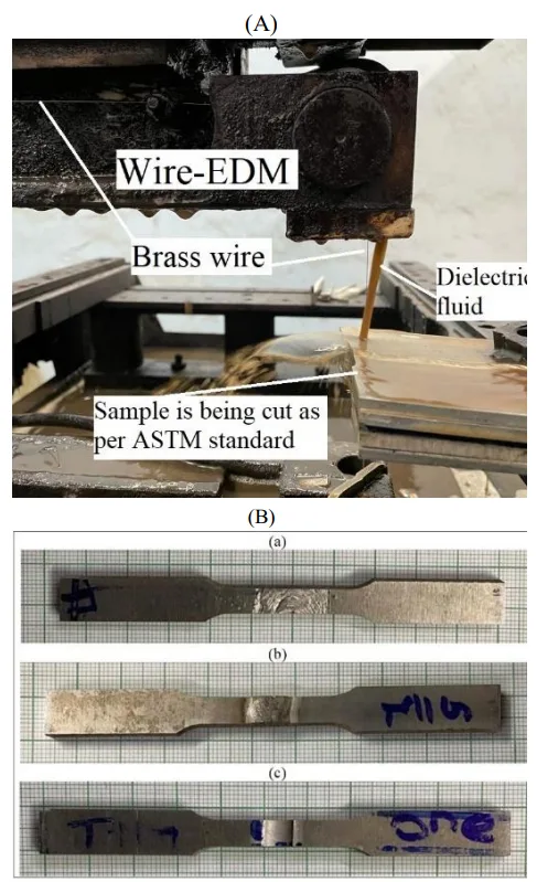
- Tensile Testing: Specimens were cut via wire-EDM according to ASTM-E8 standard and tested on a Universal Testing Machine to generate load-displacement curves and determine UTS, YS, and elongation.
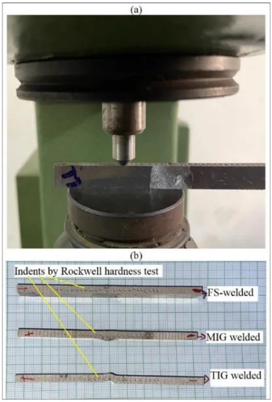
- Hardness Testing: A Rockwell hardness tester (B-scale) was used to take indentations at 2 mm intervals across the cross-section of the welded joints.
- Fractography: The fractured surfaces of the tensile specimens were examined under a FESEM machine to analyze the fracture mode.
- Microstructural Analysis: Cross-sections of the welds were polished and etched with 2% hydrofluoric acid (HF) to reveal the grain structure of the BM, HAZ, and WZ for microscopic observation.
Research Topics and Scope:
The research focused exclusively on Al-6061 plates. The scope was to compare the mechanical and microstructural properties resulting from three specific welding techniques: filler-less solid-state FSW, filler-based arc MIGW, and filler-less arc TIGW.
6. Key Results:
Key Results:
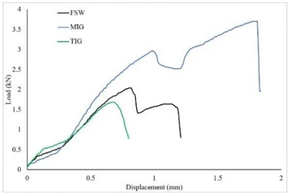
- Tensile Properties: The MIGW sample showed the highest UTS (154 MPa) and elongation (2.4%). The FSW sample had a UTS of 88 MPa and 1.6% elongation. The TIGW sample had the lowest UTS (73 MPa) with 1.7% elongation (Table 1).
- Hardness: The MIGW plate showed the highest hardness in all zones (Base, HAZ, WZ). The WZ of the MIGW sample was significantly harder (92 HRB) than the WZ of the FSW (34 HRB) and TIGW (21 HRB) samples. In the TIGW sample, the HAZ (30 HRB) was harder than the WZ (21 HRB) (Figure 8).
- Fracture Behavior: All joints exhibited ductile fracture. The MIGW sample showed significant plastic flow and macro-dimples. The FSW sample showed some plastic flow but negligible dimples. The TIGW sample showed a "whirl-like appearance" (Figure 6).
- Microstructure: In MIGW and TIGW, the WZ showed thick, dendritic grain boundaries, a change from the fine boundaries in the base metal. In FSW, the WZ (stirred zone) grains were finer than the base metal, and no clear boundary was visible between the WZ and HAZ, indicating proper stirring (Figure 10).
Figure Name List:
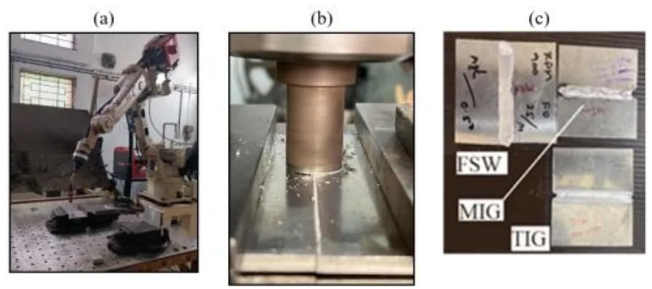
- Fig. 1 Experimental work: (a) Automatic MIG welding; (b) FSW process; (c) Three welded plates
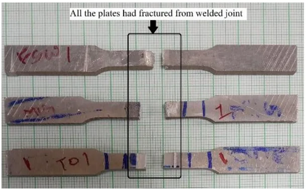
- Fig. 2 (A) Cutting of tensile test specimen according to ASTM-E8 standard; (B) Three tensile test specimens of- (a) FSW plate; (b) MIGW plate; (c) TIGW plate
- Fig. 3 Rockwell hardness testing: (a) Image during indentation at a gap of 2 mm; (b) The tested specimens
- Fig. 4 The outcome of tensile testing in the form of Load-Displacement curves: (a) Blue colored curve- MIGW; (b) Black colored curve- FSW; (c) Green colored curve- TIGW
- Fig. 5 Fractured tensile test specimens
- Fig. 6 Fractography analysis of welded joint: (a) FSW joint; (b) MIG joint; (c) TIG joint
- Fig. 7 Hardness distribution at various points of the welded plates
- Fig. 8 A comparative assessment among hardness at BM, HAZ and WZ
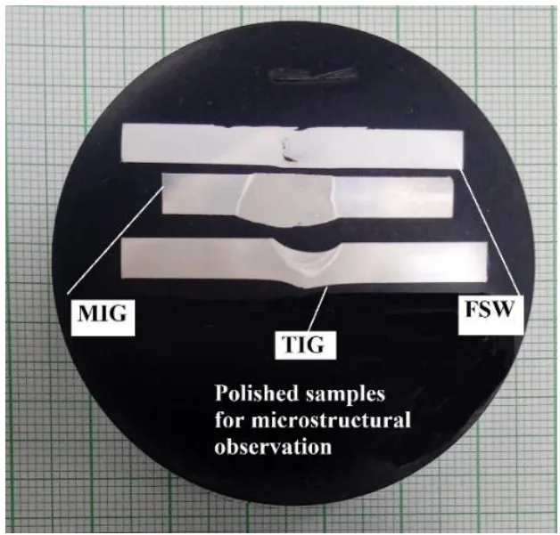
- Fig. 9 Polished and etched surfaces of three welded plates
- Fig. 10 Microstructural observation in FSW plate
- Fig. 11 Microstructural observation in MIGW plate
- Fig. 12 Microstructural observation in TIGW plate
7. Conclusion:
The paper concludes that Al-6061 has good weldability. The MIGW plate, using a filler, showed the highest UTS, YS, and elongation. FSW, a filler-less process, had better UTS than TIGW but lost some ductile properties. The results prove that "insertion of filler wire is highly necessary in the case of arc welding." The hardness of the MIGW welded zone was significantly higher than the others. Microstructurally, the study confirmed that FSW resulted in proper mixing, while arc welding created dendritic structures in the weld zone. Overall, the paper identifies "MIG welding with filler wire" as the "highly suitable method for joining Al-plates as far as good strength, high ductility, and high hardness is concerned."
8. References:
- O. Yakubu, I. Usman, A. Aliyu, O.O. Emmanuel: Nigerian Journal of Technology, 35(1), 2015, 122-128. https://doi.org/10.4314/njt.v35i1.19.
- A.M. Samuel, F.H. Samuel, C. Villeneuve, H.W. Doty, S. Valtierra: International Journal of Cast Metals Research, 14, 2001, 97-120. https://doi.org/10.1080/13640461.2001.11819429.
- I. Polmear, D. St John, J.-F. Nie, M. Qian. Chapter 1: The Light Metals. In.: Light Alloys: From Traditional Alloys to Nanocrystals. Fifth Edition, Butterworth-Heinemann: Oxford, 2017, 1-29. https://doi.org/10.1016/B978-0-08-099431-4.00001-4.
- A. Laska, M. Szkodo, D. Koszelow, P. Cavaliere: Metals, 12, 2022, 192. https://doi.org/10.3390/met12020192.
- F. Gulshan, Q. Ahsan: Chemical and Materials Engineering, 2, 2014, 25-32.
- M. Samiuddin, J. Li, M. Taimoor, M. N. Siddiqui, S. U. Siddiqui, J. Xiong: Defence Technology, 17, 2021, 1234-1248. https://doi.org/10.1016/j.dt.2020.06.012.
- M. Dorta-Almenara, M. C. Capace: Revista Facultad de Ingeniería, 25, 2016, 7–19. https://doi.org/10.19053/01211129.v25.n43.2016.5293.
- I. Sevim, F. Hayat, Y. Kaya, N. Kahraman, S. Sahin: The International Journal of Advanced Manufacturing Technology, 66, 2013, 1825-1834. https://doi.org/10.1007/s00170-012-4462-z.
- V. Saravanan, S. Rajakumar, A. Muruganandam: Metallography, Microstructure and Analysis, 5, 2016, 476-485. https://doi.org/10.1007/s13632-016-0315-8.
- P. Carlone, G. S. Palazzo: Metallography, Microstructure and Analysis, 2, 2013, 213-222. https://doi.org/10.1007/s13632-013-0078-4.
- V. Saravanan, N. Banerjee, R. Amuthakkannan, S. Rajakumar: Metallography, Microstructure and Analysis, 4, 2015, 178-187. https://doi.org/10.1007/s13632-015-0199-z.
- R. Sachin, A. Sumesh, U.S. Upas: Materials Today: Proceedings, 24, 2020, 1167-1173. https://doi.org/10.1016/j.matpr.2020.04.430.
- S. Dewangan, R. Yadav, A. Sharma, S. Vohra: Advances in Processing of Lightweight Metal Alloys and Composites. In: Vignesh, R.V., Padmanaban, R., Govindaraju, M. (eds) Advances in Processing of Lightweight Metal Alloys and Composites. Materials Horizons: From Nature to Nanomaterials. Springer: Singapore, 2023, 281-298. https://doi.org/10.1007/978-981-19-7146-4_16.
- X. Kuang, B. Qi, H. Zheng: Journal of Materials Research and Technology, 20, 2022, 3391-3407. https://doi.org/10.1016/j.jmrt.2022.08.094.
- V. Manikandan, K. Mariselvam, R. Nekin Joshua, С. Ramesh, K. Arunprasath: Materials Today: Proceedings, 66, 2022, 683-689. https://doi.org/10.1016/j.matpr.2022.03.641.
- D.T.L. Alexander, A.L. Greer: Acta Materialia, 50, 2002, 2571-2583. https://doi.org/10.1016/S1359-6454(02)00085-X.
- I. Polmear, D. St John, J.-F. Nie, M. Qian. Light Alloys: Metallurgy of the Light Metals. Butterworth-Heinemann: Oxford, 2017, 31-107. https://doi.org/10.1016/B978-0-08-099431-4.00002-6.
Conclusion & Next Steps
This research provides a valuable and clear roadmap for engineers selecting a joining process for Al-6061 components. The data-driven findings leave no doubt that for applications where mechanical performance is paramount, the choice of welding method and the strategic use of filler material are critical decisions. The dramatic improvement in strength, ductility, and hardness achieved with MIG welding demonstrates a clear path toward more robust and reliable aluminum assemblies.
At CASTMAN, we are dedicated to applying the latest industry research to solve our customers' most challenging die casting problems. Understanding the downstream processing of our components, like welding, is key to total product success. If the issues discussed in this paper resonate with your operational goals, contact our engineering team to discuss how we can help you design high-integrity components optimized for their final application.
Expert Q&A: Your Top Questions Answered
Q1: Which welding method produced the strongest and most ductile joint for Al-6061 in this study?
A1: The MIGW (Metal Inert Gas Welding) method produced the strongest and most ductile joint. As shown in Table 1 of the paper, the MIGW sample had an ultimate tensile strength (UTS) of 154 MPa and an elongation of 2.4%, both significantly higher than the FSW and TIGW samples.
Q2: According to the paper, why was the MIG weld so much stronger than the TIG weld?
A2: The paper's Conclusion section explicitly states that the "insertion of filler wire is highly necessary in the case of arc welding." The MIG weld was performed with an ER5183 filler rod, while the TIG weld was filler-less. This was the key differentiating factor responsible for the superior strength of the MIG joint.
Q3: What was the most interesting finding regarding the hardness of the TIG weld?
A3: For the TIG weld, the Heat-Affected Zone (HAZ) was found to be harder than the Welded Zone (WZ). The paper's Abstract and Hardness test analysis section attribute this to "the accumulation of fine equiaxed secondary phase" in the HAZ. This is contrary to the MIG and FSW joints, where the WZ was harder than the HAZ.
Q4: What specific material was investigated in this research?
A4: The research was conducted on "welded Al-6061 plates," as stated clearly in the Abstract and Keywords sections.
Q5: What was the failure mode observed in the tensile tests?
A5: The Fractography analysis section and the Abstract both state that the results "established the ductile behavior of all three joints." While the degree of plastic deformation varied, with MIG showing the most, all three failure modes were identified as ductile fractures.
Q6: What is the direct, practical takeaway from this paper for a manufacturing facility joining Al-6061 parts?
A6: The core takeaway, as summarized in the paper's Conclusion, is that "MIG welding with filler wire has been proven as the highly suitable method for joining Al-plates as far as good strength, high ductility, and high hardness is concerned."
Copyright
- This material is an analysis of the paper "A COMPARATIVE ANALYSIS AMONG THE WELDED Al-6061 PLATES JOINED BY FSW, MIG AND TIG WELDING METHODS" by A. P. Reddy and S. Dewangan.
- Source of the paper: https://doi.org/10.36547/ams.29.2.1778
- This material is for informational purposes only. Unauthorized commercial use is prohibited.
- Copyright © 2025 CASTMAN. All rights reserved.