How Casting Method Impacts Fatigue Life in Al-Si Alloys: A Fractography Analysis
This technical summary is based on the academic paper "THE FRACTOGRAPHY STUDY OF FATIGUE FRACTURE SURFACES IN Al-Si CAST ALLOYS" by L. Hurtalová, E. Tillová, M. Chalupová, published in Powder Metallurgy Progress, Vol.15 (2015), special issue.
![Fig.1. Three stages of fatigue fracture [3]](https://castman.co.kr/wp-content/uploads/image-3390.webp)
Keywords
- Primary Keyword: Fatigue Fracture in Al-Si Alloys
- Secondary Keywords: Fractography Analysis, Al-Si Cast Alloys, Casting Defects, Fatigue Life, Intermetallic Phases, Sand Casting vs. Chill Casting
Executive Summary
- The Challenge: The reliability and fatigue life of critical aluminum-silicon cast components are often compromised by inherent casting defects and microstructural inconsistencies.
- The Method: Researchers performed a detailed fractography study using scanning electron microscopy (SEM) on fatigue-fractured AlSi9Cu3 alloy samples produced by two distinct methods: slow-cooling sand casting and rapid-cooling chill casting.
- The Key Breakthrough: The study confirmed that casting defects like pores are the primary fatigue initiation sites, while the cooling rate (determined by the casting method) significantly alters the morphology of silicon particles and intermetallic phases, which in turn governs the mechanisms of crack propagation and final failure.
- The Bottom Line: Selecting and controlling the casting process to refine microstructure and minimize porosity is a critical, actionable strategy for enhancing the fatigue performance of Al-Si alloy components.
The Challenge: Why This Research Matters for HPDC Professionals
In demanding industries like automotive and aerospace, component failure is not an option. Aluminum-silicon (Al-Si) alloys are valued for their light weight and castability, but their mechanical properties and in-service reliability can be unpredictable. The primary culprits are defects and inhomogeneities—such as porosity, oxide inclusions, and coarse microstructures—that are introduced during the casting process. These imperfections act as stress concentrators, becoming the preferential sites where fatigue cracks initiate, leading to premature failure under cyclic loading. For any engineer designing or manufacturing moving parts, from engine blocks to aircraft fuselages, understanding the root cause of fatigue is essential for ensuring safety, reliability, and component longevity. This research directly addresses this challenge by dissecting how the choice of casting technology fundamentally influences the material's internal structure and its subsequent resistance to fatigue.
The Approach: Unpacking the Methodology
The study employed a comparative approach to isolate the effects of the casting process on fatigue behavior. The methodology was robust, ensuring the findings are directly applicable to industrial scenarios.
Method 1: Material Selection
The researchers used a recycled (secondary) AlSi9Cu3 cast alloy, a common material in high-temperature applications. The chemical composition was verified for two batches, as detailed in Table 1 of the paper.
Method 2: Casting Processes
To create distinct microstructures, two casting methods with different cooling rates were used:
- Sand Casting: Samples were cast into a sand mold, resulting in a slower cooling rate and a coarser granular structure.
- Chill Casting: Samples were cast into a metallic mold, resulting in a higher cooling rate and a finer-grained structure.
Method 3: Mechanical Testing & Analysis
Fatigue tests were conducted to fracture the samples under cyclic loading. The resulting fracture surfaces were then meticulously examined using a scanning electron microscope (SEM) to identify the specific features associated with each stage of fatigue failure.
The Breakthrough: Key Findings & Data
The fractographic analysis revealed a clear, three-stage failure process and highlighted critical differences between the sand-cast and chill-cast materials.
Finding 1: Casting Defects are the Undisputed Origin of Fatigue Failure
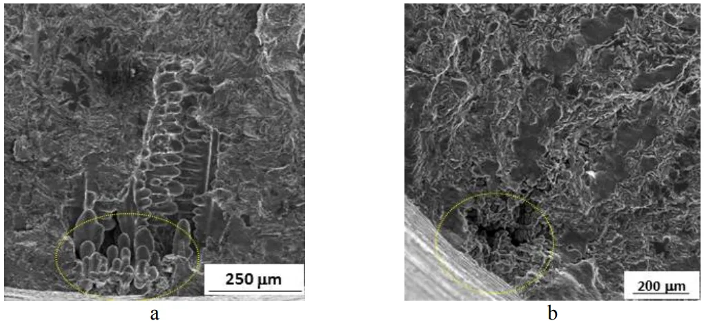
The study unequivocally identified casting defects as the initiation sites for fatigue cracks (Stage I) in both sample types. As shown in Figure 4, pores and microshrinkage located near the component surface acted as the starting points for failure. This confirms that minimizing porosity through process control is the first line of defense in designing fatigue-resistant cast components.
Fig.4. Fractography analysis of the initiation sites (Stage I), SEM a) sand mould cast alloy; b) chill mould cast alloy.
Finding 2: Microstructure Governs How Cracks Grow and Components Fail
The morphology of the material's microstructure, directly influenced by the casting method's cooling rate, dictated the characteristics of crack propagation (Stage II) and final rupture (Stage III).
Stable Crack Growth (Stage II): This stage was characterized by the transcrystalline fatigue fracture of the ductile aluminum (α-phase) matrix. However, the path of the crack was heavily influenced by brittle particles. Smooth, flat fracture areas seen in Figures 5b and 6b were identified as fractured Fe-rich intermetallic phases and Si particles. These brittle phases offer easy paths for crack propagation, accelerating failure.
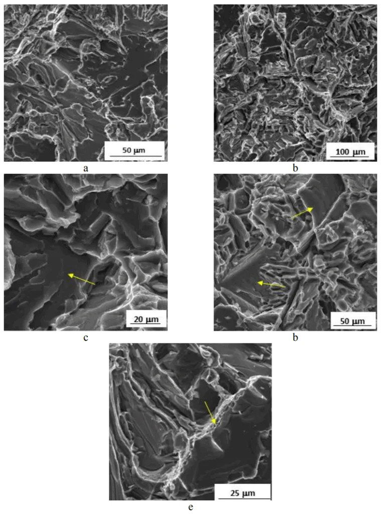
Final Rupture (Stage III): The final, rapid fracture was a mixed-mode failure. The aluminum matrix and Cu-rich phases failed in a ductile manner (with visible plastic deformation), while the large, brittle eutectic Si particles and Fe-rich phases failed via transcrystalline cleavage (a sharp, brittle break), as shown in Figure 7. The dominance of this brittle cleavage fracture, especially in materials with coarser microstructures, contributes to a lower overall toughness.
Practical Implications for R&D and Operations
- For Process Engineers: This study suggests that adjusting the cooling rate is a powerful tool for improving fatigue resistance. For components subjected to high cyclic stress, employing chill casting or other rapid solidification techniques can refine the microstructure, reducing the size of brittle Si and Fe-rich phases and thereby impeding crack propagation.
- For Quality Control Teams: The data in Figure 4 and Figure 7 of the paper illustrates the effect of casting defects on initiation and microstructure on fracture mode. These images serve as an excellent visual reference for failure analysis, enabling teams to diagnose field failures and correlate them back to specific process parameters or material inconsistencies.
- For Design Engineers: The findings indicate that since fatigue cracks initiate at surface defects, component design should aim to minimize stress concentrations in these critical near-surface regions. Furthermore, specifying a casting process known to produce high surface integrity and low porosity (like high-pressure die casting) is a crucial design-phase decision for fatigue-critical applications.
Paper Details
THE FRACTOGRAPHY STUDY OF FATIGUE FRACTURE SURFACES IN Al-Si CAST ALLOYS
1. Overview:
- Title: THE FRACTOGRAPHY STUDY OF FATIGUE FRACTURE SURFACES IN Al-Si CAST ALLOYS
- Author: L. Hurtalová, E. Tillová, M. Chalupová
- Year of publication: 2015
- Journal/academic society of publication: Powder Metallurgy Progress, Vol.15, special issue
- Keywords: Fatigue of Al-Si alloys, fatigue fracture surfaces, fractography analysis of Al-Si alloys
2. Abstract:
The contribution describes fractography study of the Al-Si fracture surface characteristics. The characteristics of an Al-Si fracture surface depend on structural parameters morphology and porosity. The morphology of structural parameters and porosity depends on used technologies of Al-Si cast founding. Recycled (secondary) aluminium cast alloys contain more additions that form various intermetallic phases in microstructure. It is necessary to study the fatigue fracture surfaces in order to observe the influence of structural parameters of different size, amount, dispositions, morphology, etc.. The fatigue fracture surfaces were observed using scanning electron microscopy SEM after the fatigue test. The results showed that the existence of casting defects and different morphology of structural parameters (especially eutectic Si particles and Fe-rich intermetallic phases) has considerable influence on fatigue fracture surfaces in both types of experimental materials. The fatigue area of stable crack propagation region consists of transcrystalline fatigue fracture of a-phase with smooth areas (especially Fe-rich phases) (Stage II). Fatigue striations were observed very sporadically. The final phase (Stage III) of fatigue fracture consists of transcrystalline ductile fracture of Al matrix (a-phase - with plastic strain ranges) and Cu-rich intermetallic phases; and with transcrystalline cleavage fracture of Si particles and Fe-rich phases.
3. Introduction:
The most widely used technologies for founding Al castings are sand casting and die casting. The cooling rate during casting significantly affects the final microstructure and properties. Slower cooling rates, as in sand casting, result in a coarser granular structure and lower properties, while higher cooling rates from metallic molds (chill casting) produce a fine-grained structure and higher properties. The primary cause of lower mechanical properties and reliability in aluminum cast alloys is the presence of defects and inhomogeneities, which can serve as preferential sites for fatigue initiation. Fatigue is a critical failure mode for components in motion, affecting industries from automotive to aerospace. Therefore, studying the fatigue lifetime of Al alloys is of significant importance.
4. Summary of the study:
Background of the research topic:
The fatigue behavior of Al-Si cast alloys is fundamentally linked to their microstructure, which is determined by the founding technology. Key factors include porosity, the morphology of eutectic silicon, and the presence of various intermetallic phases formed from additions in the alloy, particularly in recycled materials.
Status of previous research:
Previous work, such as that by B. Zhang et al. [6], established that fatigue crack initiation is dependent on cooling rates. In materials solidified at slow cooling rates, cracks initiate from porosity, whereas in materials with increased cooling rates, initiation occurs at near-surface eutectic microconstituents. The general process of fatigue is understood to consist of three stages: initiation (I), stable crack growth (II), and final sudden fracture (III).
Purpose of the study:
The study aimed to investigate and provide a better understanding of how different casting methods (sand casting vs. chill casting) influence the structural parameters and, consequently, the fatigue fracture surface characteristics in a recycled AlSi9Cu3 cast alloy.
Core study:
The core of the study is a fractographic analysis of fatigue fracture surfaces from samples produced by both sand and chill casting. Using scanning electron microscopy (SEM), the investigation systematically identified and characterized the features of the three stages of fatigue fracture, linking them to specific microstructural components like the α-phase matrix, Si particles, and Fe-rich intermetallic phases.
5. Research Methodology
Research Design:
The study was a comparative analysis of two sets of experimental materials derived from the same AlSi9Cu3 recycled alloy but processed using different casting methods: sand casting (by Uneko, spol.s.r.o.) and chill casting (by Confal a.s.). This design allowed for the direct observation of the influence of cooling rate on microstructure and fracture behavior.
Data Collection and Analysis Methods:
- Material Characterization: The chemical composition of both experimental materials was determined using arc spark spectroscopy (Table 1).
- Fatigue Testing: Sand cast samples were tested on a ROTOFLEX rotating bending fatigue machine (30 Hz, R = -1). Chill cast samples were tested on a Vibrophores Amsler 50 – 250 HFP 5100 testing machine with a symmetrical push-pull load. All tests were conducted at room temperature (20 ± 5°C).
- Fractographic Analysis: After testing to failure, the fracture surfaces were examined using a VEGA LMU II scanning electron microscope (SEM) to identify features responsible for crack initiation and propagation.
Research Topics and Scope:
The research focused on the fractographic characteristics of fatigue fracture in AlSi9Cu3 alloy. The scope included identifying the initiation sites (Stage I), analyzing the stable crack propagation region (Stage II), and characterizing the final rupture zone (Stage III). The analysis specifically investigated the fracture behavior of the different microstructural constituents: α-matrix, eutectic Si particles, and Fe-rich and Cu-rich intermetallic phases.
6. Key Results:
Key Results:
- The three stages of fatigue fracture were identified in both sand-cast and chill-cast materials. High stress amplitudes resulted in a small fatigue region and a large final rupture zone, while lower stress amplitudes led to an increased fatigue region (stable crack propagation).
- Stage I (Initiation): Fatigue fracture initiated at casting defects, specifically pores and microshrinkage, located near the surface of the test samples for both casting types.
- Stage II (Stable Crack Propagation): This region was characterized by transcrystalline fatigue fracture of the α-phase. Smooth, featureless areas within this region were identified as fractured Fe-rich phases and Si particles. Classic fatigue striations were observed only sporadically.
- Stage III (Final Rupture): The final failure was a composite of different fracture modes. It consisted of transcrystalline ductile fracture of the Al matrix (α-phase) and Cu-rich intermetallic phases, combined with transcrystalline cleavage fracture of the brittle eutectic Si particles and Fe-rich intermetallic phases.
Figure Name List:
- Fig.1. Three stages of fatigue fracture [3]
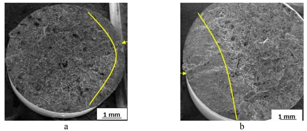
- Fig.2. Typical fatigue fracture surfaces (Stage I, Stage II, Stage III) for experimental samples casted into a sand mould, SEM a) σa = 88 MPa, Nf = 11 560 cycles; b) σa = 54 MPa, Nf = 5.10⁶ cycles
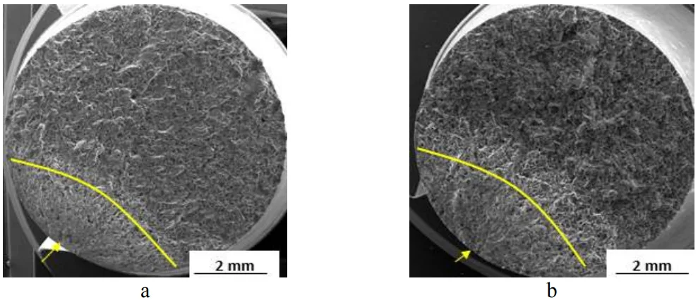
- Fig.3. Typical fatigue fracture surfaces (Stage I, Stage II, Stage III) for experimental samples casted into a metallic mould, SEM a) σa = 85 MPa, Nf = 2,8.10⁶ cycles; b) σa = 50 MPa, Nf = 2.10⁷ cycles
- Fig.4. Fractography analysis of the initiation sites (Stage I), SEM a) sand mould cast alloy; b) chill mould cast alloy.
- Fig.5 Fractography analysis of the stable crack propagation in samples casted into a sand mould (Stage II), SEM a) Stage II; b) smooth areas – Fe-rich phases and Si particles; c) area between Stage II and Stage III
- Fig.6 Fractography analysis of the stable crack propagation in samples casted into a metallic mould (Stage II), SEM a) Stage II; b) smooth areas – Fe-rich phases and Si particles; c) area between Stage II and Stage III.
- Fig.7 The final rupture fractography analysis of both experimental materials, SEM a) Stage III in sand mould samples; b) Stage III in metallic mould samples; c) fracture of Si particles; d) fracture of Fe-rich phases; e) fracture of Cu-rich phases.
7. Conclusion:
Different casting methods resulted in changes to the morphology of structural components, particularly eutectic silicon and Fe-based intermetallic phases. These morphologies significantly affect the fatigue fracture surface. Pores (casting defects) served as initiation sites for fatigue crack propagation in both sample types. The hard and brittle eutectic Si particles and Fe-rich intermetallic phases lead to transcrystalline and intercrystalline fatigue fracture and transcrystalline cleavage fracture. The matrix containing Cu-rich intermetallic phases exhibits transcrystalline fatigue fracture and transcrystalline ductile fracture. The final rupture surface is formed from transcrystalline cleavage and ductile fracture, with cleavage being dominant and related to large plate-like Si particles and brittle iron intermetallics. The ductile fracture of the Al matrix is observed on a smaller portion of the surface.
8. References:
- [1] http://www.azom.com/article.aspx?ArticleID=1392, available on line 16.12.2014
- [2] Avalle, M., Belingardi, G., Cavatorta, MP.: Proceedings of the Institution of Mechanical Engineers, Part L: Journal of Materials Design and Applications, vol. 216, 2002, p. 25
- [3] Fatigue – Chapter 14. ASM International. Elements of metallurgy and engineering alloys, 2008, p. 243
- [4] Belan, J.: Key Engineering Materials, vol. 635, 2014, p. 9
- [5] Uhríčik, M., Palček, P., Soviarová, A., Snopiński, P.: Manufacturing technology, vol. 14, 2014, no. 3, p. 467
- [6] Zhang, B., Chen, W., Poirier, R.: Fatigue Fracture Engineering Material Structure, vol. 23, 2000, no. 5, p. 417
- [7] Bokůvka, O., Nicoletto, G., Guagliano, M., Kunz, L., Palček, P., Nový, F., Chalupová, M. In: Fatigue of Materials at low and high frequency loading. EDIS, 2014, p. 146 ISBN 978-80-554-0857-6
- [8] Palček, P., Chalupová, M., Nicoletto, G., Bokůvka, O.: Education Aid for multimedia lectures. CETRA, 2003, p. 177 ISBN 80-8070-103-2
- [9] Moreira, MF., Fuoco, R.: AFS Transactions, vol. 2, 2006, p. 1
- [10] Gao, YX., Yi, JZ., Lee, PD., Lindley, TC.: Acta Materialia, vol. 52, 2004, no. 19, p. 5435
- [11] Bonollo, F., Tovo, R.: Fatigue in Al casting alloys: metallurgical aspects. TALAT Lecture 1254 EAA Europan Aluminium Associate, 1999
Expert Q&A: Your Top Questions Answered
Q1: Why were two different fatigue testing machines and methods used for the sand cast and chill cast samples?
A1: The paper specifies that sand cast samples were tested using a ROTOFLEX rotating bending machine, while chill cast samples were tested on a Vibrophores Amsler push-pull machine. The document does not state the reason for this difference. However, both methods subject the material to cyclic tensile and compressive stresses, allowing for a valid comparative study of the resulting fracture surfaces and fatigue mechanisms.
Q2: The paper mentions fatigue striations were "observed very sporadically." What does this imply about the fracture mechanism in this alloy?
A2: Fatigue striations are microscopic lines that mark the incremental advance of a crack front with each load cycle and are typically associated with ductile fatigue fracture. Their sporadic observation in this Al-Si alloy suggests that the dominant crack propagation mechanism is not a simple, ductile advance. Instead, the crack growth is heavily influenced by the brittle microstructural components—eutectic Si and Fe-rich phases—which fracture by cleavage, a mechanism that does not produce striations.
Q3: What specific roles did the Fe-rich and Cu-rich intermetallic phases play in the final fracture (Stage III)?
A3: The Fe-rich and Cu-rich phases played opposing roles. As shown in Figure 7d, the Fe-rich phases, being brittle, failed by transcrystalline cleavage, contributing to the overall brittle nature of the final rupture. In contrast, the paper states that the Cu-rich intermetallic phases, along with the aluminum matrix, failed via transcrystalline ductile fracture (Figure 7e), adding a small element of toughness to the final failure event.
Q4: Did the crack initiation sites differ between the sand cast and chill cast samples?
A4: According to the paper, the fundamental nature of the initiation sites was the same for both casting types: defects such as pores and microshrinkage near the surface (Figure 4). However, the paper does note one subtle difference: "The sand cast samples have more initiation sites compared to the chill cast samples that had always only one initiation site." This suggests the slower cooling of sand casting may produce a higher density of critical surface defects.
Q5: The abstract mentions "recycled (secondary) aluminium cast alloys." How might the recycled nature of the material influence the results?
A5: The paper states, "Recycled (secondary) aluminium cast alloys contain more additions that form various intermetallic phases in microstructure." This implies that the presence, size, and morphology of phases like the Fe-rich and Cu-rich intermetallics, which were shown to be critical in the fracture process, may be more pronounced or varied in recycled alloys compared to primary alloys. The study of these phases is therefore particularly important for understanding the performance of components made from secondary aluminum.
Conclusion: Paving the Way for Higher Quality and Productivity
This research provides a clear and actionable framework for understanding Fatigue Fracture in Al-Si Alloys. It demonstrates that the journey to failure begins at microscopic casting defects and is guided by the material's microstructure. The key takeaway is that the casting process itself is the most powerful tool for controlling these factors. By optimizing cooling rates and minimizing porosity, manufacturers can engineer a microstructure that is inherently more resistant to crack initiation and propagation, leading directly to components with longer service lives and greater reliability.
At CASTMAN, we are committed to applying the latest industry research to help our customers achieve higher productivity and quality. If the challenges discussed in this paper align with your operational goals, contact our engineering team to explore how these principles can be implemented in your components.
Copyright Information
This content is a summary and analysis based on the paper "THE FRACTOGRAPHY STUDY OF FATIGUE FRACTURE SURFACES IN Al-Si CAST ALLOYS" by "L. Hurtalová, E. Tillová, M. Chalupová".
Source: Powder Metallurgy Progress, Vol.15 (2015), special issue, pages 138-144.
This material is for informational purposes only. Unauthorized commercial use is prohibited.
Copyright © 2025 CASTMAN. All rights reserved.