This article introduces the paper "STUDY OF THE EFFECT OF STRUCTURAL DIE AND MACHINE VARIABLES ON DIE DEFLECTIONS".
Overview:
- Title: STUDY OF THE EFFECT OF STRUCTURAL DIE AND MACHINE VARIABLES ON DIE DEFLECTIONS
- Author: Jeeth Xavier Kinatingal, B.E.
- Publication Year: 2005
- Publishing Journal/Academic Society: The Ohio State University
- Keywords: Die Casting, Die Deflection, Structural Die Variables, Machine Variables, Parting Plane Separation
Research Background:
- Social/Academic Context of the Research Topic:
- High-pressure die casting is a prime production option for volume production of functional products.
- Die casting allows for components to be cast at high speed with intricate design details and close tolerances.
- Maintaining dimensional integrity of die casting dies is crucial for producing high quality castings.
- Die casting dies deflect due to thermal and mechanical loads acting during the die casting cycle.
- Limitations of Existing Research:
- Previous studies successfully matched simulation results and field observations regarding flash location.
- However, some stress results for the hot die were not as expected, indicating inconsistencies.
- It remained unclear which die and machine parameters significantly affect die deflections and to what extent.
- Necessity of the Research:
- Understanding the influence of die and machine parameters on die deflection is essential.
- This understanding is necessary to implement structural modifications to minimize die deflections and distortions.
- Minimizing die deflection and distortion ultimately leads to minimizing part distortion and improving the quality of die cast products.
Research Purpose and Research Questions:
- Research Purpose:
- To study the effect of structural die and machine variables on die deflection.
- To clarify inconsistencies observed in previous stress analysis results of a commercial die casting die.
- Key Research Questions:
- What is the effect of die and machine variables on maximum parting plane separation?
- Which primary variables have the most significant impact on the parting plane separation?
- Research Hypotheses:
- The research aims to generate prediction models for maximum parting plane separation to understand the effect of different variables and their interactions.
- The study also seeks to establish guidelines for die design and machine selection based on the findings.
Research Methodology
- Research Design:
- The research is divided into two parts:
- Continuation and conclusion of work on a commercial die casting die.
- Computational parametric study to investigate the effect of structural die and machine variables on die deflection.
- The research is divided into two parts:
- Data Collection Method:
- ABAQUS simulations were used to generate data for both parts of the research.
- An experimental array was designed for the parametric study to systematically vary die and machine variables.
- Analysis Method:
- Finite Element Analysis (FEA) using ABAQUS version 6.3 was employed for simulations.
- Regression analysis was performed using MINITAB [28] and SPSS [29] to analyze the simulation results and develop prediction models.
- Sensitivity analysis was conducted to assess the influence of individual variables on die deflection.
- Research Subjects and Scope:
- Part 1: A commercial die casting die was used for channel plate stress analysis.
- Part 2: A parametric study was conducted by varying the following structural die and machine variables:
- Die size (A)
- Die thickness (B)
- Platen thickness (C)
- Thickness ratio (D), defined as the ratio of shoulder thickness to die thickness
- Die location (E), defined as the distance between the die center of pressure and the platen center line
Main Research Results:
- Key Research Results:
- "The results indicate that small thin dies perform better than large thick dies."
- "It also shows that there are significant interactions between the variables and it is these interactions rather than the variables themselves that determine the system performance."
- Optimum factor settings for minimizing parting plane separation were identified for different die sizes, die thicknesses, and platen thicknesses.
- Statistical/Qualitative Analysis Results:
- Regression models were developed to predict maximum parting plane separation (Y) and maximum separation around the cavity (Yc).
- For maximum parting plane separation (Y), the edited prediction model in coded units is:
- Ypred = 10.9608 + 0.8755A + 1.2277B - 1.7718C - 0.7501D + 1.8216A2 - 2.6985AB - 1.9871AC + 0.6837B*C
- For maximum separation around the cavity (Yc), the edited prediction model in coded units is:
- Ycpred = -14.0273 + 1.9853A + 3.6203B - 4.0056C + 24.158D + 0.1913C2 - 0.1065AB - 0.0776AC + 0.1536BC - 5.0826B*D
- Sensitivity analysis revealed the relative sensitivity of parting plane separation to each variable at specific operating points.
- Power law models were explored but did not provide as good a fit to the data as quadratic models.
- Data Interpretation:
- Interactions between die size, die thickness, and platen thickness are crucial in determining die deflection.
- Machine rigidity is a dominant factor influencing die deflection.
- "A thicker platen was found to be invariably better than a thinner platen."
- "Dies which had up to 50% platen area coverage performed better than the larger dies."
- "Thicker die steel behind the insert reduced the parting plane separation."
- Figure Name List:
- Figure 1.1: Schematic showing the principal components of a hot chamber die casting machine [6]
- Figure 1.2: Schematic showing the principal components of a cold chamber die casting machine [6]
- Figure 2.1: The loads acting in different stages of a die casting operation [16]
- Figure 2.2: Dimensional changes in the various steps of the die casting process [18]
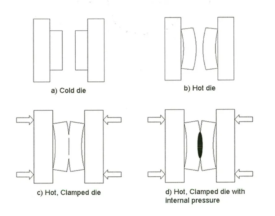
- Figure 2.3: Die distortion process in a die casting cycle
- Figure 2.4: Schematic of the machine model used by Choudhary, et al [26]
- Figure 3.1: Machine model used for simulation
- Figure 3.2: Cover die with pillars that have been added in the new model
- Figure 3.3: Contour plot for maximum principal stresses in the cover insert for the "cold die" case
- Figure 3.4: Contour plot for maximum principal stresses in the cover insert for the "hot die" case
- Figure 3.5: Contour plot for maximum principal stresses in the ejector insert for the "cold die" case
- Figure 3.6: Contour plot for maximum principal stresses in the ejector insert for the "hot die" case
- Figure 3.7: Contour plot for maximum principal stresses in the cover die for the "cold die" case
- Figure 3.8: Contour plot for maximum principal stresses in the cover die for the "hot die" case
- Figure 3.9: Contour plot for maximum principal stresses in the ejector die for the "cold die" case
- Figure 3.10: Contour plot for maximum principal stresses in the ejector die for the "hot die" case
- Figure 3.11: Contour plot for the displacement pattern in the inserts for the "hot die" case
- Figure 3.12: A schematic showing the location of pillars and cooling lines on (a) cover die and (b) ejector die
- Figure 3.13: Contour plot for the cover die displacement pattern for the "hot die" case
- Figure 3.14: Contour plot for the ejector die displacement pattern for the "hot die" case
- Figure 3.15: Contour plot for parting plane separation for "hot die" case with (a) clamp only and (b) clamp plus intensification
- Figure 3.16: Contour plot for contact pressure for "cold die" case with (a) clamp only and (b) clamp plus intensification
- Figure 3.17: Contour plot for contact pressure for "hot die" case with (a) clamp only and (b) clamp plus intensification
- Figure 4.1: Schematic of die geometry
- Figure 4.2: Layout of machine platen
- Figure 4.3: Casting used for the study
- Figure 4.4: Boundary conditions [10]
- Figure 4.4: Parting plane separation pattern for case 1 (Note: Figure number duplication in source)
- Figure 4.5: Parting plane separation pattern for case 2
- Figure 4.6: Plot of Y and Yc for the design runs
- Figure 4.7: Interaction between die size and die thickness
- Figure 4.8: Interaction between die size and platen thickness
- Figure 4.9: Interaction between die thickness and platen thickness
- Figure 4.10: Interaction between die size and thickness ratio
- Figure 4.11: Interaction between die thickness and thickness ratio
- Figure 4.12: Interaction between platen thickness and thickness ratio
- Figure 4.17: Interaction between die size and die thickness (Ycpred)
- Figure 4.18: Interaction between die size and platen thickness (Ycpred)
- Figure 4.19: Interaction between die size and thickness ratio (Ycpred)
- Figure 4.20: Interaction between die thickness and platen thickness (Ycpred)
- Figure 4.21: Interaction between die thickness and thickness ratio (Ycpred)
- Figure 4.22: Interaction between platen thickness and thickness ratio (Ycpred)
- Figure 4.23: Contour plot of dY/dA at C = -1
- Figure 4.24: Contour plot of dY/dA at C = 0
- Figure 4.25: Contour plot of dY/dA at C = 1
- Figure 4.26: Contour plot of dY/dB
- Figure 4.27: Contour plot of dY/dC
- Figure 4.28: Contour plot of dYc/dA
- Figure 4.29: Contour plot of dYc/dB
- Figure 4.30: Contour plot of dYc/dC
- Figure A.1: Parting plane separation plot for case 1
- Figure A.2: Parting plane separation plot for case 2
- Figure A.3: Parting plane separation plot for case 3
- Figure A.4: Parting plane separation plot for case 4
- Figure A.5: Parting plane separation plot for case 5
- Figure A.6: Parting plane separation plot for case 6
- Figure A.7: Parting plane separation plot for case 7
- Figure A.8: Parting plane separation plot for case 8
- Figure A.9: Parting plane separation plot for case 9
- Figure A.10: Parting plane separation plot for case 10
- Figure A.11: Parting plane separation plot for case 11
- Figure A.12: Parting plane separation plot for case 12
- Figure A.13: Parting plane separation plot for case 13
- Figure A.14: Parting plane separation plot for case 14
- Figure A.15: Parting plane separation plot for case 15
- Figure A.16: Parting plane separation plot for case 16
- Figure A.17: Parting plane separation plot for case 17
- Figure A.18: Parting plane separation plot for case 18
- Figure A.19: Parting plane separation plot for case 19
- Figure A.20: Parting plane separation plot for case 20
- Figure A.21: Parting plane separation plot for case 21
- Figure A.22: Parting plane separation plot for case 22
- Figure A.23: Parting plane separation plot for case 23
- Figure A.24: Parting plane separation plot for case 24
- Figure A.25: Parting plane separation plot for case 25
- Figure A.26: Parting plane separation plot for case 26
- Figure A.27: Parting plane separation plot for case 27
- Figure A.28: Parting plane separation plot for case 28
- Figure A.29: Parting plane separation plot for case 29
- Figure A.30: Parting plane separation plot for case 30
- Figure A.31: Parting plane separation plot for case 31
![Figure 1.1: Schematic showing the principal components of a hot chamber die casting
machine [6]](https://castman.co.kr/wp-content/uploads/image-144-png.webp)
![Figure 2.1: The loads acting in different stages of a die casting operation [16]](https://castman.co.kr/wp-content/uploads/Figure-2.1-The-loads-acting-in-different-stages-of-a-die-casting-operation-16-.webp)
Conclusion and Discussion:
- Summary of Main Results:
- The channel plate stress analysis clarified inconsistencies in previous simulation results, attributing high stresses to thermal growth and insert crowning.
- The parametric study on structural die and machine variables indicated that "small thin dies perform better than large thick dies" in minimizing parting plane separation.
- Significant interactions between variables, particularly die size, die thickness, and platen thickness, are crucial determinants of die deflection.
- Optimum settings for minimizing parting plane separation were identified, suggesting that a thicker platen and higher thickness ratio generally reduce separation.
- Academic Significance of the Research:
- The research provides valuable insights into the complex behavior of die deflection in die casting processes.
- It demonstrates the effective use of computer-aided analysis tools, specifically FEA and regression analysis, for understanding and predicting die behavior.
- The study contributes to the body of knowledge on die design and optimization in die casting.
- Practical Implications:
- The findings offer practical guidelines for die designers and machine operators to minimize die deflection.
- Guidelines include considering die size and thickness in conjunction with platen thickness and thickness ratio for optimal performance.
- The research suggests that for small to medium sized dies, thin dies are preferable, while for larger dies, thicker dies may be necessary.
- Utilizing thicker platens and higher thickness ratios, implying stiffer machines, generally leads to reduced parting plane separation.
- Limitations of the Research:
- Inconsistencies in boundary conditions in previous analyses were addressed but highlight the challenges in complex FEA modeling.
- Power law models, while explored for better understanding, were not as accurate as quadratic models for prediction.
- The rear platen was not explicitly modeled, potentially overlooking its influence on parting plane separation.
Future Follow-up Research:
- Directions for Follow-up Research:
- Investigate the effects of varying cover and ejector die thicknesses as separate variables.
- Study the influence of the number and distribution of pillars on die deflection.
- Model the rear platen explicitly to capture its effect on parting plane separation.
- Conduct similar analysis using design of experiments to validate computational findings in real-world scenarios.
- Areas Requiring Further Exploration:
- Further exploration is needed to optimize die design by considering the complex interactions of various die and machine variables.
- Investigating the optimum balance between die compliance and stiffness for different die sizes and casting parameters warrants further research.
References:
- [1] Chase, H., "Die Castings", John Wiley & Sons Inc., 1934
- [2] Idra-Prince, Die Casting Process Control course. Course notes, 2002, Idra-Prince, Holland, Michigan
- [3] Ahhuet-Garza, H., Miller, R.A., Mobley, C, "Die Casting", Modeling for casting and solidification processing. Marcel Dekker Inc., 2002
- [4] Doehler,H.H., "Die Casting", First Edition, McGraw-Hill Company Inc., 1951
- [5] Bradley, E.F., "High Performance Castings - A Technical Guide", ASM International, 1989
- [6] Sully, L.J.D., "Die Casting", ASM Metals Handbook, Vol.15, Casting, Ninth Edition, 1988
- [7] NADCA, "NADCA Product Specification Standards for Die Casting", Third Edition, NADCA, 1997
- [8] Ashish Vashist, "A study of industrial die casting die to predict parting plane separation and location of flash with different support setups". The Ohio State University, 2003
- [9] Vashist, A., Kabiri-Bamoradian, K., Miller, R.A., "Die casting die distortion: Case study to predict parting plane separation and flash location", NADCA Transactions of the Congress & Table Exposition, Rosemont, Illinois, 2002
- [10] Abhijith Chayapathi, "Study of the effect of structural die and machine variables on die deflections". The Ohio State University, 2000
- [11] Chayapathi, A., Kesavan, V., Miller, R.A., "The effects of structural die and machine variables on die deflection". Transactions of the 20th NADCA Congress & Exposition, Cleveland, Ohio, 1999
- [12] Abhay Tewari, "Study of the effect of structural variables of die and die casting machine on die deflections". The Ohio State University, 2000
- [13] Miller, R.A., Chakravarthi, V., Kabiri-Bamoradian, K., Kulkami, Y., Tewari, A., "Modeling the Distortion and Mechanical Performances of Dies", NADCA Transactions, 2000
- [14] Yogesh S Kulkami, "Study of the effect of structural variables of die and die casting machine on die deflections", The Ohio State University, 2001
- [15] Miller, R.A., "Die deflection modeling: Empirical validation and tech transfer". Final report. Center for Die Casting, The Ohio State University, 2003
- [16] Ahuett-Garza, H., Miller, R.A., "Die casting die deflections: Computer simulation of causes and effects", NADCA Transactions, 1997
- [17] Kaye, A., Street, A., "Die Casting Metallurgy", Butterworth Scientific, 1982
- [18] Barone, M.R., Caulk, D.A., "Analysis of Thermo-Mechanical Distortion in Die Casting", NADCA Transactions, 1999
- [19] Ahuett-Garza, H., Hedge, K., Padiyar, G., Miller, R.A., "FEM analysis of die casting die deflections: Part I, Modeling and Simulation", NADCA Transactions, 1995
- [20] Ahuett-Garza, H., Hedge, K., Padiyar, G., Miller, R.A, "FEM analysis of die casting die deflections: Part II, Results", NADCA Transactions, 1995
- [21] Papai, J., Mobley, C; "Die thermal fields and heat fluxes during die casting of 380 aluminum alloy in H-13 steel dies"; NADCA Transactions, 1991
- [22] MAGMAsoft, User's manual, 3.2 ed; MAGMA Foundry Technologies, Inc., 1998
- [23] IDEAS Version 10, Online Help Manual, Structural Dynamics Research Corporation
- [24] ABAQUS Version 6.3, Online Documentation, Hibbitt, Karlsson and Sorrensen, Inc.
- [25] Dedhia, S., Ahuett-Garza, H., Choudhury, A.K., and R.A. Miller, "Analysis of proud inserts in Die Deflections and Slide Blowback in Die Casting Dies", Transactions, 19th NADCA Congress & Exposition, Minneapolis, MN, 1997
- [26] Choudhury, A.K., Dedhia, S., Ahuett-Garza, H., and R.A. Miller, "Study of the effects of platen size on die deflections". Transactions, 19th NADCA Congress & Exposition, Minneapolis, MN, 1997
- [27] Venkat, G, R., Shah, V., Ahuett-Garza, H., Miller, R.A., "Parametric design applied to die casting", NADCA Transactions, 1995
- [28] MINITAB version 14, Minitab Inc.
- [29] SPSS version 12, SPSS Inc.
Copyright:
This material is Jeeth Xavier Kinatingal's paper: Based on STUDY OF THE EFFECT OF STRUCTURAL DIE AND MACHINE VARIABLES ON DIE DEFLECTIONS.
This material was summarized based on the above paper, and unauthorized use for commercial purposes is prohibited.
Copyright © 2025 CASTMAN. All rights reserved.