This introductory paper is the research content of the paper "High-speed computer tomography employed in pressure die casting" published by Giesserei-Verlag.
![Figure 1: In a high-speed, automatic helix in-line CT unit the gantry, which accommodates the x-ray tube and the
multi-line detector arranged opposite, rotates about the specimens on the conveyor belt [6]](https://castman.co.kr/wp-content/uploads/image-1540-1024x808.webp)
1. Overview:
- Title: High-speed computer tomography employed in pressure die casting
- Author: Eberhard Ambos, Oliver Brunke, Dirk Neuber, Holger Lux, Ingo Stuke, Wolfgang Besser, Mike Ziesemann, Christian Heikel and Andrea Huxol
- Publication Year: 2012
- Published Journal/Society: Casting Plant & Technology
- Keywords: The paper does not explicitly use the term. (computer tomography, CT, pressure die casting, non-destructive testing, porosity, quality assurance, dimensional accuracy)
2. Abstract
The continuous efforts of automotive industries to cut down on fuel consumption and reduce environmental impact affect aluminum alloy die castings. The paper presented the results and experience from the world's first high-speed computer tomography (CT) application in pressure die casting, preparing for a specific case of series production.
3. Research Background:
Background of the research topic:
- Automotive industry efforts to reduce fuel consumption and environmental footprint are leading to lighter die castings with thinner walls.
- Components are becoming larger, more complex, with increasing functional integration.
- Material strength specifications, especially dynamic strength, are becoming more exacting.
Status of previous research:
- Existing research has focused on developing calculation procedures for highly stressed Al pressure die castings, considering defects [1-4].
- Common 2-D X-ray testing is insufficient for providing rapid, comprehensive information about castings.
- Conventional industrial computer tomography systems are limited in use to large foundries operated by carmakers.
Need for research:
- Growing awareness among customers of die casting shops regarding the importance of understanding porosity (location, volume, and size) in castings.
- Need for faster, more efficient non-destructive testing techniques to meet demands of manufacturing dynamics and delivery performance.
- Need to minimize time from pattern development to series production.
4. Research purpose and research question:
Research purpose:
- To verify the suitability of high-speed CT for testing die-cast parts under production conditions.
- To enhance porosity simulations in castings by providing data on the exact positions and volumes of pores.
- To evaluate the dimensional accuracy of measurements obtained from the newly developed high-speed CT system.
Core research:
- The core research of this paper is around below questions:
- Can high-speed CT provide accurate and timely data on porosity and dimensional accuracy in die castings?
- How well do simulation results of porosity correspond with tomograms from high-speed CT scans?
5. Research methodology
- Research Design: Experimental and comparative study.
- Data Collection: High-speed CT scanning of aluminum die castings (pedestals for oil pumps), metallographic examinations, fringe pattern projections, and touch probe measurements.
- Analysis Method: Comparison of simulation results with tomograms, validation of volume defects through metallographic examinations, and assessment of dimensional accuracy by comparing CT measurements with touch probe and fringe projection data.
- Research Topic and Scope: Evaluation of high-speed CT for porosity detection and dimensional measurement in aluminum die castings.
- Equipment Used: Initially, a laboratory-scale high-speed CT unit (Figure 2) was used, and later an industrial-scale unit (Figure 3) was employed. The gantry assembly (scanning unit), which accommodates the x-ray tube, rotates about the casting to be tested, while a conveyor belt is moving the casting through the gantry at low speed. (Figure 1)
6. Key research results:
Key research results and presented data analysis:
- High-speed CT scanning rates are several hundred times higher than conventional CT systems.
- The system operates in a helical mode (multi-plane or multi-line helix CT), making the process faster and reducing artifacts of movement [5].
- The industrial-scale unit has specific technical data, including maximum test piece size, high-capacity x-ray tube specifications, reconstruction rate, and typical detail resolution (voxel size) (Page 4).
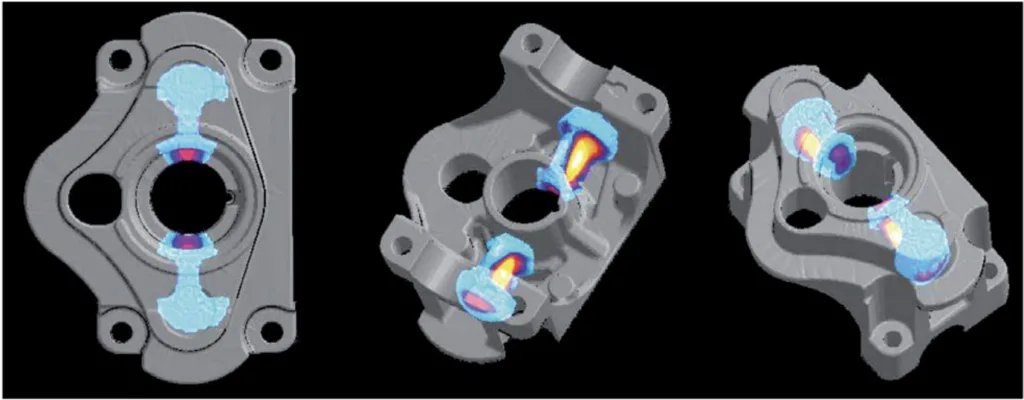
- Simulation results for hot spot identification (Figure 5) and porosity visualization (Figure 6) were compared with tomograms.
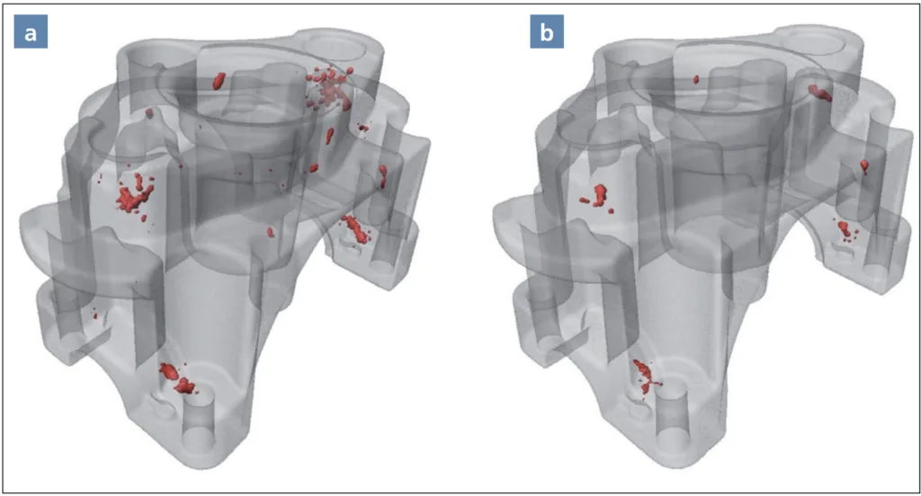
- Transparent 3-D models of test pieces showed varying degrees of porosity (Figure 7).
- Total porosity relative to the number of parts was measured and ranged from 0.2491% to 0.4667% (Figure 8).
- Metallographic examinations validated the volume defects found in the tomograms (Figures 9 and 10).
- Dimensional deviations of the tomograms were compared with fringe-projection-based measurements (Figure 11) and a chosen nominal distance was measured using both methods (Figure 12).
- High correspondence was found between CT data, touch probe measurements (±10 µm accuracy), and fringe projection data.
- Integrating the high-speed CT system can be performed in "at-line" (Figure 13) or "in-line" (Figure 14) arrangements.
List of figure names:
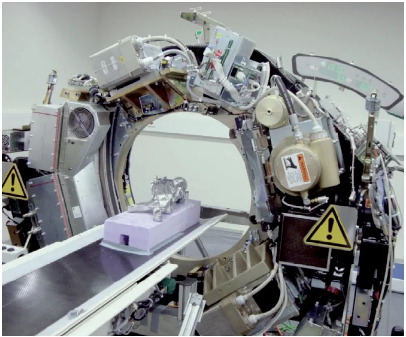
- Figure 1: In a high-speed, automatic helix in-line CT unit the gantry, which accommodates the x-ray tube and the multi-line detector arranged opposite, rotates about the specimens on the conveyor belt [6]
- Figure 2. Laboratory-scale high-speed CT scanning a die casting
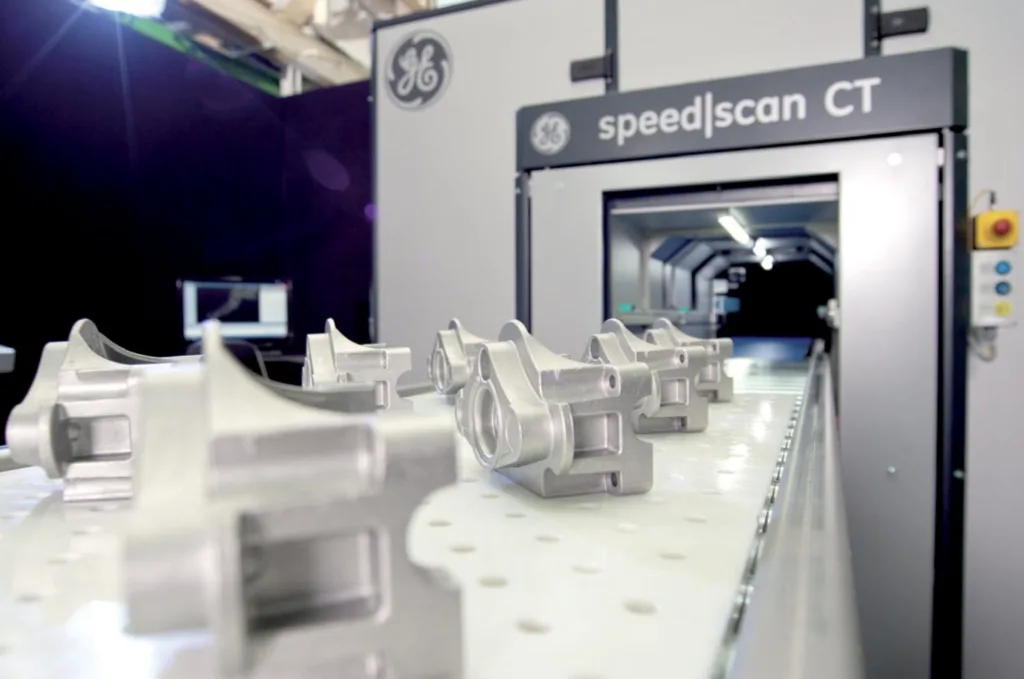
- Figure 3: Series-type high-speed CT unit
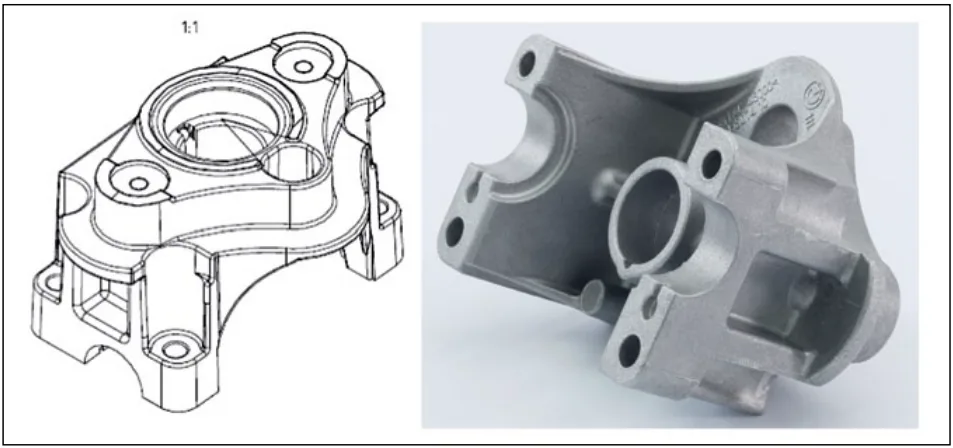
- Figure 4: The scanned aluminum die casting
- Figure 5: Simulation of the test piece for hot spot identification in different planes of the part (forecast locations of volume deficits due to shrinkage; color scale: turquoise approx. after 18 s, light red after approx. 20 s, yellow after approx. 21 s)
- Figure 6: Simulation of the test piece visualizing porosity in different planes of the part (red: probability of pore formation approx. 50%, yellow: 75 to 85% and white 100%)
- Figure 7: Transparent 3-D model of the test pieces: a) with the highest degree of porosity (part No. 4) and b) with the lowest degree of porosity (part No. 10)
- Figure 8: Total porosity relative to number of parts
- Figure 9: Metallographic examination of part No. 4, the part with the highest porosity in Figure 7a
- Figure 10: Metallographic examination of part No. 10, the part with the lowest porosity in Figure 7b
- Figure 11: Dimensional deviations of the tomograms versus the fringe-projection-based measurement of part No. 5
- Figure 12: Chosen nominal distance of 91.000 mm measured by high-speed CT and by fringe projection
- Figure 13: High-speed CT system in at-line arrangement
- Figure 14: High-speed CT system in in-line arrangement: (1) roller table, (2) roller table with lifting system for level adjustment, (3) slide gates (radiation protection), (4) scanning unit (gantry), (5) specimen, (6) radiation-proof cabin
7. Conclusion:
Summary of key findings:
- High-speed CT is suitable for testing die-cast parts under production conditions, providing accurate and timely data on porosity and dimensional accuracy.
- There is a high degree of correspondence between simulation results, tomograms, and metallographic examinations.
- The system offers a high repetition accuracy for defect volume measurements.
- High-speed CT can be integrated into the production flow, streamlining the quality control process and enhancing simulation accuracy.
- This technology is mature for industrial production and highly efficient.
- The research demonstrates high-speed computer tomography can be used to sophisticate strength calculations for aluminum die castings.
Possible areas for future expansion research:
- Further research is needed to determine the detection limits of individual pores and their minimum dimensions.
- Future developments may focus on enlarging the specimen accommodation space for testing larger components.
- Continued research and collaboration with additional partners are planned to further develop the technology and its applications.
8. References:
- [References] www.giesserei-verlag.de/cpt/references
9. Copyright:
- This material is a paper by "Eberhard Ambos, Oliver Brunke, Dirk Neuber, Holger Lux, Ingo Stuke, Wolfgang Besser, Mike Ziesemann, Christian Heikel and Andrea Huxol": Based on "High-speed computer tomography employed in pressure die casting".
- Source of paper: www.giesserei-verlag.de/cpt/references
This material was created to introduce the above paper, and unauthorized use for commercial purposes is prohibited. Copyright © 2025 CASTMAN. All rights reserved.