Automated Defect Analysis in HPDC: How Fringe Projection Boosts Quality and Die Life
This technical summary is based on the academic paper "Study of automated procedures for surface defects analysis on die-cast components by using fringe projection systems" by Marco Menoncin, Andrea Nicolini, Giorgio Cavaliere, and Enrico Savio, published in euspen's 20th International Conference & Exhibition (2020).
Keywords
- Primary Keyword: Automated Defect Analysis HPDC
- Secondary Keywords: Fringe Projection System, High-Pressure Die-Casting, Surface Defect Inspection, In-line Metrology, Quality Control, Die Maintenance
Executive Summary
- The Challenge: High-pressure die-casting requires fast, reliable, and quantitative analysis of surface defects for both part quality assurance and die-life monitoring, which traditional methods struggle to provide in a production environment.
- The Method: The study evaluated an automated Fringe Projection System (FPS) to detect and measure raising surface defects on an aluminum alloy die-cast component for an automotive PCB.
- The Key Breakthrough: The automated FPS successfully detected and quantified critical defects with acceptable accuracy for production tolerances, enabling a repeatable, in-line inspection process that reduces manual labor and inspection time.
- The Bottom Line: Automated fringe projection is a feasible and effective technology for in-line quality control in HPDC, providing crucial data for improving part functionality and enabling preventive maintenance of casting dies.
The Challenge: Why This Research Matters for HPDC Professionals
In the high-pressure die-casting industry, ensuring the quality of functional surfaces is paramount. Surface defects, such as casting burrs or raisings, can compromise part assembly, mating, and overall functionality. For a component like an automotive electrical PCB case, such defects on internal surfaces could damage sensitive components or cables.
Furthermore, these defects are often replicas of cracks that form on the die surfaces due to thermo-mechanical fatigue. Monitoring the size and location of these replicated defects provides invaluable "backward information" on the health of the die. This allows for continuous monitoring of die conditions, enabling preventive maintenance actions like repair or replacement before catastrophic failure occurs.
The primary challenge has been the lack of fast, automated, and quantitative inspection methods suitable for the production floor. Traditional CMMs are too slow, and manual inspection is subjective and labor-intensive. This research was necessary to validate an advanced optical technique that could overcome these limitations and bring quality control directly in-line with manufacturing.
The Approach: Unpacking the Methodology
The study focused on a real-world industrial component: an aluminum alloy case for an automotive electrical PCB, manufactured via high-pressure die-casting. The research aimed to validate an automated inspection process using a Fringe Projection System (FPS).
Method 1: System and Specimen Setup
- Equipment: A GOM Atos Capsule FPS, featuring a robotic arm and a rotary table to enable fully automated scanning. The sensor had a resolution of 12 million points per scan.
- Specimen: An aluminum alloy die-cast case.
- Key Variables: Two different measuring volumes were tested to assess the impact of resolution on defect detection: MV120 (120x80x60 mm) and MV200 (200x140x140 mm).
Method 2: Measurement and Reference Comparison
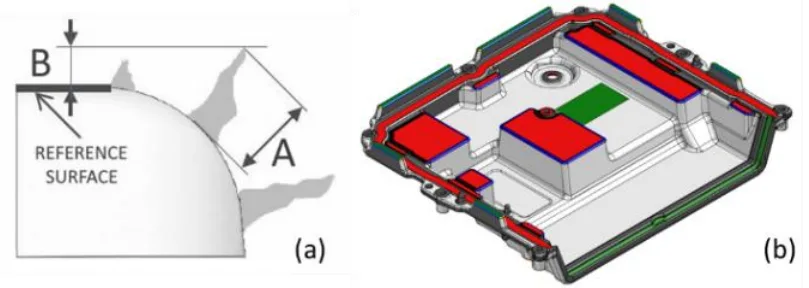
- Target Measurands: The study focused on two critical measurements for raising defects, as illustrated in Figure 1(a):
- A) Absolute Height: The defect's height normal to the surface, relevant for monitoring die crack propagation.
- B) Asymmetric Height: The defect's height relative to a specific datum surface, critical for ensuring clearance for the PCB assembly. The most restrictive tolerance was 0.1 mm for this measurement.
- Reference Method: To validate the FPS performance, reference measurements were obtained using high-resolution optical profilometry with the focus variation principle, which was determined to be the best compromise of resolution, accuracy, and acquisition time.
Method 3: Automated Data Processing
- Software: The GOM Inspect software suite was used for data processing and analysis.
- Procedure: A scripted, automated evaluation routine was developed. This involved aligning the scanned point cloud to the nominal CAD model, identifying defect locations using a "Surface Defects Map" tool based on local curvature deviations, and then automatically calculating the required height measurements (A and B).
The Breakthrough: Key Findings & Data
The investigation yielded clear results on the feasibility and performance of the automated FPS for this demanding application.
Finding 1: FPS Achieves Quantitative Defect Evaluation within Production Tolerances
The study found that the choice of measuring volume was critical. The MV200 configuration lacked the necessary resolution to properly digitize the fine surface irregularities. In contrast, the MV120 configuration produced a detailed point cloud sufficient for analysis. When comparing the FPS results for the most challenging asymmetric height (B) measurement against the high-resolution focus variation reference, the data showed a consistent, minor deviation.
As noted in the paper, "The comparison between FPS and focus variation measured values showed an average deviation of -0,028 mm (±0.006 mm std. error 2σ)." The FPS measurements were systematically smaller due to smoothing effects from its lower structural resolution. However, this deviation was considered fully satisfactory and acceptable relative to the tightest tolerance of 0.1 mm.
Finding 2: A Fully Automated Inspection Routine is Practical and Repeatable
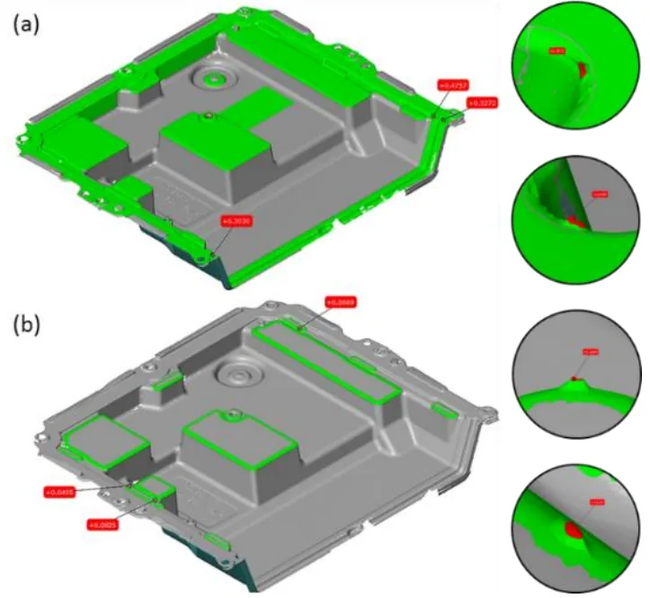
The research successfully demonstrated a complete, automated workflow. By implementing the evaluation procedure using the scripting tool in GOM Inspect, the system could perform the entire analysis without operator intervention after the initial setup. This automated process, shown conceptually in Figure 2, involves:
1. Aligning the scan to the CAD model.
2. Automatically detecting defects using the Surface Defect Map.
3. Calculating absolute and asymmetric heights based on pre-defined rules.
4. Generating a colored deviation map for easy visualization of results.
This automation is key to enabling in-line application, as it ensures high measurement repeatability, significantly reduces inspection time, and eliminates operator-to-operator variability.
Practical Implications for R&D and Operations
- For Process Engineers: This study suggests that implementing an automated FPS can provide rapid feedback on how process variations affect defect formation. The ability to track the growth of raising defects over a production run offers a powerful tool for scheduling preventive die maintenance and optimizing die life.
- For Quality Control Teams: The data in the paper illustrates the capability of FPS to replace slower, subjective inspection methods with a fast, quantitative, and repeatable process directly in the manufacturing environment. This enables 100% inspection where required and provides robust digital records for traceability.
- For Design Engineers: The findings indicate that the system can precisely measure defects in high-stress areas like fillet radii. This data can be fed back into the design phase to create geometries that are less prone to die cracking and subsequent defect formation on the cast part.
Paper Details
Study of automated procedures for surface defects analysis on die-cast components by using fringe projection systems
1. Overview:
- Title: Study of automated procedures for surface defects analysis on die-cast components by using fringe projection systems
- Author: Marco Menoncin¹, Andrea Nicolini², Giorgio Cavaliere³, Enrico Savio¹
- Year of publication: 2020
- Journal/academic society of publication: euspen's 20th International Conference & Exhibition, Geneva, CH, June 2020
- Keywords: surface defects analysis, high-pressure die-casting quality control, fringe projection system, in-line metrology
2. Abstract:
Quantitative surface defects analysis in high-pressure die-casting is relevant both for quality assurance of part functionality and for monitoring the functional surfaces of dies. Advanced optical techniques for digitization of parts enable fast identification of surface irregularities and their measurement. The use of automation and appropriate enclosures enables quality control operations directly in the manufacturing environment, increasing measurement repeatability, reducing inspection time and direct labour resources. The paper reports on a case study and illustrates the implementation of a fringe projection system for the analysis of surface defects on high-pressure die-castings, including the development of automated evaluation routines.
3. Introduction:
The use of coordinate measuring systems based on optical principles is well established in manufacturing industry quality assurance, with automation enabling in-line control and process optimization. A challenging application is the in-line detection and measurement of surface imperfections. This study aims to assess the automated use of a fringe projection system (FPS) to analyze surface defects on aluminium alloy high-pressure die-castings. The evaluation of raising defects is relevant for part functionality (e.g., assembly) and for monitoring die functional surfaces, as casting burrs replicate cracks on dies from thermo-mechanical fatigue. Therefore, in-line inspection facilitates preventive maintenance and continuous monitoring of casting equipment.
4. Summary of the study:
Background of the research topic:
The research is set against the backdrop of modern manufacturing's need for in-line quality control and feedback-based process optimization. Specifically, it addresses the challenge of quantitatively analyzing surface defects on high-pressure die-castings, which is critical for both part conformity and the monitoring of die health.
Status of previous research:
The paper acknowledges that optical coordinate measuring systems are well-established for quality assurance [1]. It cites existing research on thermo-mechanical fatigue cracking in die-casting dies as the root cause of the raising defects being studied [2]. It also references work comparing different optical measurement systems for industrial component verification [3] and international standards for areal surface texture measurement methods [4].
Purpose of the study:
The purpose is to assess the feasibility of using an automated fringe projection system (FPS) to detect and quantitatively analyse surface defects on aluminium alloy high-pressure die-castings. The study aims to develop and validate automated procedures suitable for in-line quality control directly in the manufacturing environment.
Core study:
The core of the study is a case study on an aluminium alloy case for an automotive electrical PCB. It investigates the performance of a GOM Atos Capsule FPS in measuring two types of raising defect heights (absolute and asymmetric). The FPS measurements are compared against a reference method (focus variation optical profilometry). The study evaluates the effect of different sensor measuring volumes on resolution and develops an automated point cloud processing routine using GOM Inspect software to streamline the inspection process from data acquisition to final report.
5. Research Methodology
Research Design:
The study employed a comparative experimental design. The performance of an automated Fringe Projection System was evaluated against a reference measurement method (focus variation). The investigation was conducted on a real industrial component to ensure the relevance of the findings. Repeatability was assessed by conducting each part acquisition three times for each FPS configuration.
Data Collection and Analysis Methods:
Data was collected using a GOM Atos Capsule FPS with 12-million-point resolution, testing two measuring volumes (MV120 and MV200). The reflex detection setting was used to manage the part's surface reflectivity. The acquired point cloud data was processed using GOM Inspect software. Defect identification was performed using the Surface Defects Map tool, and geometric analysis was conducted to measure defect heights consistently with the procedure used for the reference data.
Research Topics and Scope:
The research is focused on the application of FPS for surface defect analysis on high-pressure die-cast aluminium alloy components. The scope is specifically on "raising defects" or burrs caused by die cracks. The analysis is quantitative, focusing on two specific measurands: absolute height (relevant to die wear) and asymmetric height (relevant to part function), with tolerances as tight as 0.1 mm. The study also covers the development of an automated evaluation procedure.
6. Key Results:
Key Results:
- The measuring volume MV200 (200x140x140 mm) did not provide sufficient resolution to digitize the surface irregularities and was not processed further. The MV120 (120x80x60 mm) volume yielded a more detailed point cloud suitable for defect analysis.
- A comparison between FPS and the reference focus variation method showed an average deviation of -0.028 mm (with a standard error of ±0.006 mm at 2σ). The FPS measurements were systematically smaller due to smoothing effects from its lower structural resolution and reconstruction accuracy.
- Despite the systematic deviation, the results were deemed fully satisfactory for the intended use, as the smoothing effect on defect height was acceptable relative to the most restrictive tolerance (0.1 mm).
- The "Surface Defects Map" tool in GOM Inspect successfully enabled the identification of all relevant defects on all acquired datasets.
- An automated procedure for point cloud processing was successfully implemented using scripting, enabling high measurement repeatability, reduced inspection time, and limiting operator interaction, making it suitable for in-line application.
Figure Name List:
- Figure 1. Measurement requirements (a) and tolerance-related areas (b)
7. Conclusion:
The case study demonstrated the feasibility of automated detection and quantitative evaluation of surface defects on die-cast parts using fringe projection systems. A task-specific metrological performance investigation identified a fulfilling system configuration in relation to the measurement requirements. Automated procedures were successfully tested and applied, proving effective in reducing inspection time and enabling in-line control directly in the manufacturing environment.
8. References:
- [1] Gao W et al.2019 On-machine and in-process surface metrology for precision manufacturing CIRP Ann. 68 no. 2 843-866
- [2] Klobčar D et al. 2012 Thermo fatigue cracking of die-casting dies Eng. Fail. Ann. 20 43-53
- [3] Guerra M G et al. 2019 Measuring techniques suitable for verification and repairing of industrial components: A comparison among optical systems CIRP J. Manuf. Sci. Technol. vol. 27 114-123
- [4] ISO 25178-600:2019 Geometrical Product Specifications (GPS) Surface Texture: Areal - Part 600: Metrological characteristics for areal topography measuring methods
- [5] GOM GmbH 2017 GOM Inspect Software Manuals; ATOS Professional - Direct help; GOM Inspect Software - Scripting
- [6] Dury M R et al. 2017 Characterising 3D optical scanner measurement performance for precision engineering Proc. - ASPE 2016 Annu. Meet. January 2017 167-172
- [7] Mendricky R 2016 Determination of measurement accuracy of optical 3D scanners MM Sci. J. December 2016 1565-1572
Expert Q&A: Your Top Questions Answered
Q1: Why was a fringe projection system (FPS) specifically chosen for this study on die-cast components?
A1: The paper explains that advanced optical techniques like FPS are chosen because they enable fast identification and measurement of surface irregularities. The key advantage highlighted is the ability to pair these systems with automation (like a robot and rotary table), which allows for quality control operations to be performed directly in the manufacturing environment. This approach increases measurement repeatability while reducing inspection time and direct labor costs.
Q2: What were the specific defects being measured and why were they important for both the part and the die?
A2: The study focused on "raising defects" (casting burrs) on the part surface. These are important for two reasons. For the part's functional conformity, these defects on the internal surface could interfere with or damage the electrical PCB and cables during final assembly. For the die, these defects are replicas of cracks caused by thermo-mechanical fatigue. Measuring their geometry provides backward information to analyze crack propagation on the die, enabling monitoring and preventive maintenance.
Q3: The paper mentions two measuring volumes, MV120 and MV200. Why was MV120 selected for the final analysis?
A3: The MV120 measuring volume (120x80x60 mm) was selected because it provided a higher density point-cloud. The paper states that the resolution obtained using the larger MV200 volume was "not sufficient to digitize surface irregularities," and therefore those data sets were not processed further. The smaller volume of the MV120 provided the necessary detail and structural resolution to accurately capture the geometry of the defects.
Q4: The results showed FPS measurements were systematically smaller than the reference method. Why was this considered acceptable?
A4: This systematic underestimation was attributed to the "smoothing effects resulting from FPS lower structural resolution and reconstruction accuracy." However, this was deemed acceptable because the magnitude of the deviation was small relative to the required tolerances. The average deviation was -0.028 mm, while the most restrictive tolerance for the asymmetric height (B) was 0.1 mm. The accuracy was therefore sufficient for the intended purpose of go/no-go quality control and trend monitoring.
Q5: How was the inspection process automated after the 3D scan data was acquired?
A5: The automation was achieved using the scripting tool within the GOM Inspect software. The developed procedure first aligns the scanned point cloud of the real part to the nominal CAD model using a global best-fit. Subsequently, automated tools like "Patch Compound from CAD" and "Surface Defect Map" are used to identify and measure the defects based on pre-defined criteria and tolerances, eliminating the need for manual operator interaction in the analysis phase.
Q6: What is the practical difference between the "absolute height (A)" and "asymmetric height (B)" measurements?
A6: They serve two distinct quality control purposes. The absolute height (A), measured normal to the local surface, is directly related to the depth of the crack in the die and is therefore most relevant for evaluating die wear and crack propagation. The asymmetric height (B), measured in reference to a specific datum surface, is critical for part functionality, as it determines if the defect will physically interfere with the PCB during assembly.
Conclusion: Paving the Way for Higher Quality and Productivity
The challenge of inspecting complex die-cast components quickly and reliably is a significant hurdle in modern manufacturing. This research demonstrates a clear path forward. The key breakthrough is the validation of an Automated Defect Analysis HPDC process using fringe projection technology, proving it is not just a laboratory tool but a robust solution for the production floor. By providing fast, quantitative data, this method empowers engineers to improve part quality, monitor die health in real-time, and make data-driven decisions for preventive maintenance.
At CASTMAN, we are committed to applying the latest industry research to help our customers achieve higher productivity and quality. If the challenges discussed in this paper align with your operational goals, contact our engineering team to explore how these principles can be implemented in your components.
Copyright Information
This content is a summary and analysis based on the paper "Study of automated procedures for surface defects analysis on die-cast components by using fringe projection systems" by "Marco Menoncin, Andrea Nicolini, Giorgio Cavaliere, and Enrico Savio".
Source: www.euspen.eu
This material is for informational purposes only. Unauthorized commercial use is prohibited.
Copyright © 2025 CASTMAN. All rights reserved.