This introduction paper is based on the paper "Systematic approach for automated determination of parting line for die-cast parts" published by "Elsevier".
1. Overview:
- Title: Systematic approach for automated determination of parting line for die-cast parts
- Author: Ranjit Singh, Jatinder Madan
- Year of publication: 2013
- Journal/academic society of publication: Robotics and Computer-Integrated Manufacturing
- Keywords: Die-casting, Die design, Core, Cavity, Undercut, Parting line region, Parting line
2. Abstract:
The parting line decision for die-cast parts is a non-trivial task, which depends upon a number of factors related to the part geometry and the die-casting process requirements. This is a crucial decision which not only affects the design and manufacturing of the die-casting die but the part manufacturing as well. Normally, a die-casting die-design expert invests a lot of time, effort and resources to take this decision, which affects the part manufacturing lead time and cost. A systematic approach for automated determination of the parting line for die-cast parts is presented in this paper. Unlike the previous systems, which consider part geometric factors only, the system proposed in this paper also considers the die-casting process requirements to determine the parting line in a systematic and automated manner. Here we discuss classification of the die-cast part surfaces, identification of undercuts and protrusions, identification of parting line regions, and determination of the parting line. The system generates a number of feasible parting lines in a given parting direction after applying the die-casting process requirements. Finally, the most suitable parting line is determined from the feasible parting lines considering the industry best practices. The results obtained from the system are similar to those of the industry. The proposed system would prove to be a major step towards automation of the die-casting die design, leading to design-manufacturing integration of the die-casting process.
3. Introduction:
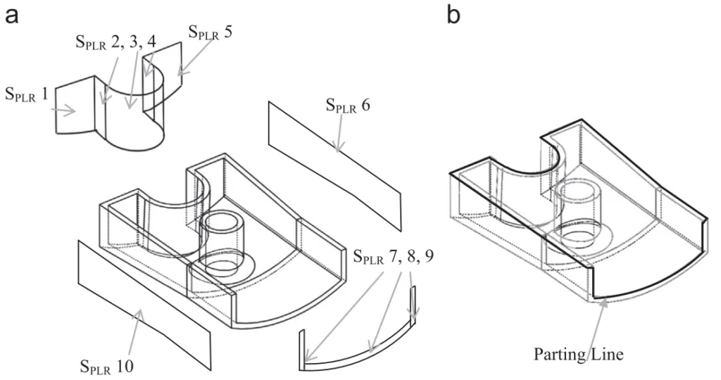
Die-casting is a near net shape metal casting process characterized by forcing molten metal under high pressure into a mold cavity created by a permanent metal mold (die) comprising two halves: core and cavity. The direction of die opening is the parting direction (PD), consisting of positive (+PD) and negative (-PD) directions. A line corresponding to the joint of the mold halves on the die-cast part is the parting line. Geometric regions that cannot be molded in the parting direction are undercuts, requiring separate side-cores. The nomenclature is illustrated in Fig. 1.
Die design is crucial, impacting cost, manufacturing time, and part quality. Activities include selecting the parting direction, determining the parting line, cavity layout, and gating system design. Conventional die design relies heavily on trial-and-error and human expertise, leading to long lead times and increased costs [2]. Automation, leveraging CAD/CAM/CAE, is highly desirable.
Parting line determination is a particularly time-consuming activity [3], requiring consideration of numerous factors related to part geometry and the die-casting process. This paper proposes a systematic approach for the automated determination of the parting line for die-cast parts, aiming to significantly reduce manufacturing lead time and cost. Key terms like Facet, V-Map, Local/Global visibility, Up/Down/Neutral facet, Core/Cavity/Core-cavity surface, Convex/Concave edge, Obstructed surface, and Parting Line Region (PLR) are defined (illustrated in Fig. 2).
4. Summary of the study:
Background of the research topic:
The determination of the parting line is a critical and complex step in die-casting die design. It significantly influences the die's manufacturability, cost, and the final quality of the cast part. Traditionally, this process is manual, experience-based, and iterative, representing a bottleneck in the design cycle.
Status of previous research:
Previous research has addressed parting direction determination [7-11], undercut feature recognition [12-19], and parting line determination [3, 20-33]. However, many approaches focus solely on geometric factors, often generate only a single feasible parting line, or are limited to specific part geometries (e.g., polyhedral, planar surfaces). Crucially, many systems do not adequately consider die-casting process requirements, such as the need for the part to remain on the core half during ejection, the movement constraints of side-cores for undercuts, the impact of protrusions on core-cavity surfaces, or the avoidance of flash on aesthetically important surfaces. Table 1 summarizes the limitations of prior work concerning these aspects. A significant gap exists in systematically integrating both geometric analysis and process constraints for automated parting line generation and selection.
Purpose of the study:
The study aims to develop and present a systematic approach for the automated determination of the parting line for die-cast parts. The key objective is to overcome the limitations of previous work by explicitly incorporating die-casting process requirements alongside geometric analysis. The system is designed to generate multiple feasible parting lines for a given parting direction and then select the most suitable one based on established industry best practices and criteria, thereby reducing design lead time and cost and facilitating design-manufacturing integration.
Core study:
The core study involves a systematic methodology implemented in three main modules (Fig. 15):
- Identification of Undercuts, Protrusions, and Classification of Part Surfaces: This module takes a tessellated part model (STL) as input. It classifies facets as up-facets, down-facets, or neutral-facets based on their orientation relative to the given parting direction (+PD) using dot products (Fig. 5). Non-convex regions are identified [31]. Undercuts (depressions) and protrusions are distinguished within non-convex regions by checking for obstructions using a modified IsObstructing algorithm [26] (Fig. 6, Fig. 7). Remaining facets are then classified into core-molded (Score), cavity-molded (Scavity), and core-cavity molded (Score-cavity) surfaces based on visibility and connectivity (Sections 4.1-4.6). The core side is identified to ensure the part stays with the core half.
- Determination of Parting Line Region (PLR): This module identifies the permissible regions (PLR) on core-cavity surfaces through which the parting line can pass. For core-cavity surfaces without features, the entire surface is the PLR. For surfaces with undercuts, the PLR is determined by subtracting an area swept based on the undercut boundary division (core/cavity segments) and the side-core movement requirement (must move with core half, +PD direction) (Fig. 8, Fig. 9). For surfaces with protrusions, the PLR is found by subtracting areas swept by the protrusion boundary in both +PD and -PD (Fig. 10). User input can exclude aesthetically sensitive areas from the PLR (Section 5, Fig. 11, Fig. 12).
- Determination and Selection of Parting Line: This module generates feasible parting lines and selects the optimal one. Feasible parting lines are constructed as closed loops comprising: (i) common edges between core and cavity surfaces (Lk), (ii) relevant boundary segments of undercuts lying on core-cavity surfaces (ELm), and (iii) feasible line segments dividing the PLR (LĮ), determined based on traversing the PLR respecting Z-coordinate constraints (Fig. 13). Multiple feasible parting line loops can be generated (Fig. 14). The optimal parting line is selected from these feasible alternatives by evaluating them against criteria derived from industry practice [34], such as dimensional stability, flatness, draw, flash, and draft, using a qualitative rating scale (Section 6, Annexure A).
5. Research Methodology
Research Design:
The research employs a constructive approach, designing and implementing a systematic computational methodology for automated parting line determination. The methodology integrates geometric reasoning based on facet visibility and connectivity with die-casting process constraints. It is structured into three sequential modules: surface classification/feature identification, PLR determination, and parting line generation/selection (Fig. 15).
Data Collection and Analysis Methods:
The primary input data is the geometry of the die-cast part, represented as a tessellated model (STL format). Geometric analysis involves calculating dot products between facet normals and the parting direction vector, identifying non-convex regions, performing visibility checks using an obstruction algorithm [26], and determining boundary curves and swept areas. Process rules, such as side-core movement constraints and part retention on the core, are encoded into the PLR determination logic. Multiple feasible parting lines are generated algorithmically based on geometric paths within the PLR and connections to core/cavity edges and undercut boundaries. The analysis culminates in the evaluation and selection of the optimal parting line using a set of qualitative criteria (dimensional stability, flatness, draw, flash, draft) based on established methods [34] and industry best practices, rated on a five-point scale (detailed in Annexure A, Table A1).
Research Topics and Scope:
The research focuses on the automated determination of the parting line for die-cast parts, given a predefined parting direction. Key topics include:
- Classification of part surfaces (core, cavity, core-cavity).
- Identification of undercut and protrusion features affecting the parting line.
- Determination of the Parting Line Region (PLR) considering process constraints (side-core movement, aesthetics).
- Generation of multiple feasible parting line candidates.
- Selection of the optimal parting line based on manufacturability criteria (dimensional stability, flatness, draw, flash, draft).
The scope assumes the input part is moldable, the parting direction is provided by the user, and the part contains no internal undercuts or intersecting/compound undercut features. While tessellated models allow handling of sculptured surfaces, the optimization of parting line geometry on such surfaces is outside the current scope.
6. Key Results:
Key Results:
A systematic approach for automated parting line determination was successfully developed and implemented using MATLAB 7.0. The system effectively integrates geometric analysis of tessellated part models with crucial die-casting process requirements. It automatically classifies surfaces, identifies undercuts and protrusions, determines the valid Parting Line Region (PLR), generates multiple feasible parting line options, and selects the optimal one based on defined criteria.
The methodology was tested on six industrial die-cast parts exhibiting varying geometric complexity (Example parts 1-6, Figs. 16-21). The results demonstrate the system's capability to handle parts with core-cavity surfaces, undercuts, and protrusions. The generated parting lines consistently align with those chosen based on industrial practice. The evaluation criteria (dimensional stability, flatness, draw, flash, draft), detailed for feasible options in Annexure A (Table A1), effectively guided the selection of the most suitable parting line in each case. The system successfully automates a significant and complex task in die design, demonstrating its potential industrial relevance and contribution towards design-manufacturing integration. Execution times ranged from seconds to minutes depending on part complexity.
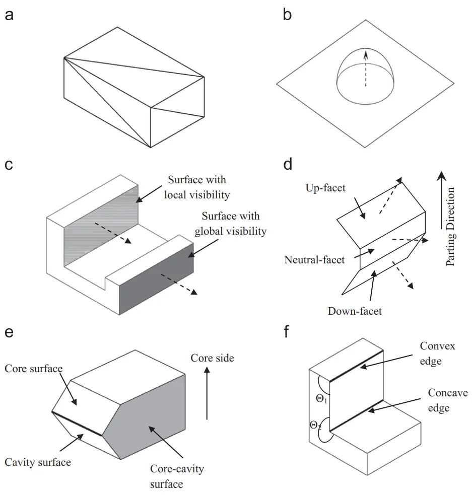
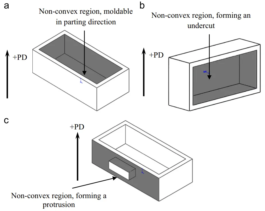
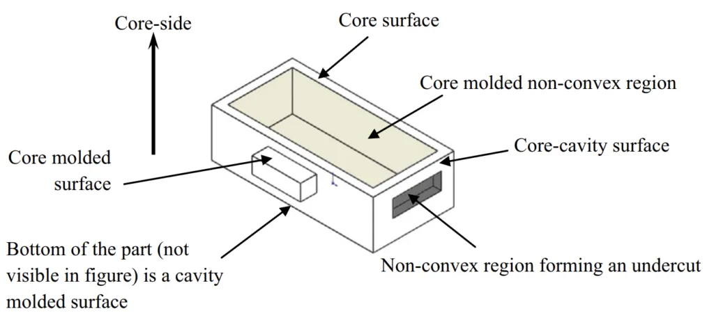
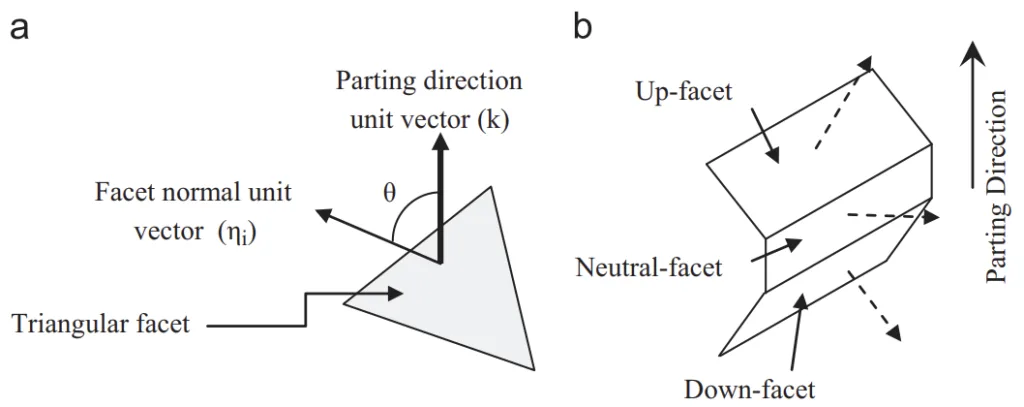
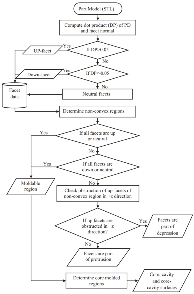
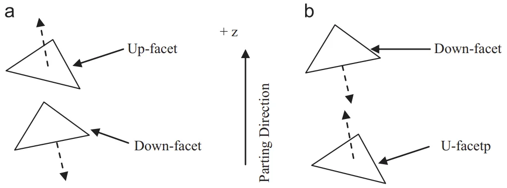
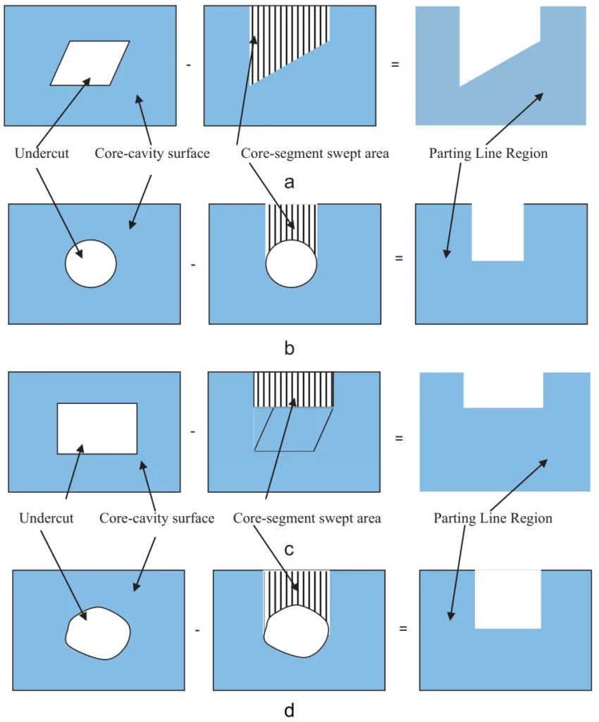
Figure and Table Name List:
- Fig. 1. Nomenclature of a die-casting die.
- Fig. 2. (a) Tessellated model of a cuboid, (b) visibility map of a point on a surface, (c) local and global visibility, (d) up-facet, down-facet and neutral-facet, (e) core surface, cavity surface and core-cavity surface and (f) convex edge and concave edge.
- Fig. 3. Non-convex regions: (a) moldable in parting direction, (b) forming an undercut and (c) forming a protrusion.
- Fig. 4. Types of regions and surfaces of a die-cast part.
- Fig. 5. (a) Dot product (DP) of facet normal and the parting direction and (b) up-facet, neutral-facet and down-facet.
- Fig. 6. (a) Protrusion feature and (b) undercut (depression) feature.
- Fig. 7. Information flow diagram for identification of undercuts, protrusions and classification of surfaces.
- Fig. 8. Determination of PLR for core-cavity surface with an undercut feature.
- Fig. 9. PLR for typical undercut shapes.
- Fig. 10. PLR of core-cavity surfaces with (a) rectangular protrusion and (b) circular protrusion.
- Fig. 11. Information flow diagram for determination of PLR.
- Fig. 12. (a) Example part for die-casting and (b) Parting Line Region for this part.
- Fig. 13. Parting line segment types and Z-range concept.
- Fig. 14. Information flow diagram for parting line determination.
- Fig. 15. Architecture of the systematic approach for parting line determination for the die-cast parts.
- Fig. 16. Example part 1 and its PLR, parting line, and feasible options.
- Fig. 17. Example part 2 and its PLR, parting line, and feasible options.
- Fig. 18. (a) Tensioner housing and its PLRs, (b) selected parting line, (c-d) feasible options.
- Fig. 19. (a) Rocker arm and its PLRs, (b) identified Parting Line, (c-d) feasible options.
- Fig. 20. (a) Example 5 die-cast part and its PLRs, (b) selected parting line, (c-d) feasible options.
- Fig. 21. (a) Die-cast part (Crank case cover) and its PLR and (b) parting line for this part.
- Table 1. Limitations of the previous research work on parting line determination.
- Table 2. Details of PLR and parting line for die-cast parts 1 and 2.
- Table 3. Details of PLR and parting line for example die-cast parts 3 and 4.
- Table 4. Details of PLR and parting line for die-cast parts 5 and 6.
- Table A1. Rating of feasible parting line options.
7. Conclusion:
This paper presented a systematic approach for the automated determination of the parting line for die-cast parts. By integrating die-casting process requirements with geometric reasoning using tessellated models, the developed system addresses key limitations of previous work. It successfully identifies relevant part features (undercuts, protrusions) and surfaces (core, cavity, core-cavity), determines the permissible Parting Line Region (PLR) considering process constraints like side-core movement, generates multiple feasible parting line candidates, and selects the optimal one based on industry-relevant criteria.
The system facilitates automation of the die-design process, reducing the time and effort required by designers, minimizing manufacturing lead time, and lowering die and part costs. It also serves as a valuable tool for design-for-manufacturing analysis. Tests on various industrial die-cast parts demonstrated the system's effectiveness and industrial relevance, producing results consistent with industry practices.
Future work includes incorporating user preferences, enhancing the capability to handle multiple stepped, tapered, and compound parting lines, and addressing intersecting undercuts and protrusions. The methodology can be integrated into commercial CAD software via APIs and contributes to the broader goal of integrated product and process development for near net shape manufacturing [35, 36].
8. References:
- [1] Fuh JYH, Wu SH, Lee KS. Development of a semi-automated die casting die design system. Proceedings of the Institution of Mechanical Engineers 2002;216(B):1575–88.
- [2] Wu SH, Fuh JYH, Lee KS. Semi-automated parametric design of gating systems for die-casting die. Computers and Industrial Engineering 2007;53(2):222–32.
- [3] Wong T, Tan ST, Sze WS. Parting line formation by slicing a 3D CAD model. Engineering with Computers 1998;14:330–43.
- [4] Li Weishi, Ralph R, Martin, Frank C, Langbein Gan GH, Woo TC, et al. Spherical maps: their construction, properties and approximation. ASME Journal of Mechanical Design 1994;116:357–63.
- [5] Elber G, Cohen E. Arbitrarily precise computation of gauss maps and visibility sets for freeform surface. In: Transactions of ACM solid modeling ’95; 1995.
- [6] Chen LL, Chou SY, Woo TC. Parting directions for mould and die design. Computer-Aided Design 1993;25:762–8.
- [7] Hui KC, Tan ST. Mould design with sweep operations—a heuristic search approach. Computer-Aided Design 1992;24(2):81–92.
- [8] Chen YH. Determining parting direction based on minimum bonding box and fuzzy logics. International Journal of Machine Tools and Manufacture 1997;37 (9):1189–99.
- [9] Yin Zhou-Ping, Ding Han, Xiong You-Lun. Mouldability analysis for near net shaped manufacturing parts using freedom cones. International Journal of Advanced Manufacturing Technology 2000;16:169–75.
- [10] Madan J, Rao PVM, Kundra TK. Optimal-parting direction selection for die-casting. International Journal of Manufacturing Technology and Management 2009;18(2):167–82.
- [11] Khardekar R, Burton G, McMains S. Finding feasible mold parting directions using graphics hardware. Computer-Aided Design 2006;38:327–41.
- [12] Fu MW, Fuh JYH, Nee AYC. Generation of optimal parting direction based on undercut features in injection moulded parts. IIE Transactions 1999;31:947–55.
- [13] Lu HY, Lee WB. Detection of interference elements and release directionin die-cast and injection-moulded components. Proceedings of the Institution of Mechanical Engineers 1999;214:431–41.
- [14] Ye XG, Fuh JYH, Lee KS. Automatic undercut feature recognition for side core design of injection molds. Journal of Mechnical Design 2004;126(3):519–26.
- [15] Yin Zhou-Ping, Ding Han, Li Han-Xiong, Xiong You-Lun. Geometric mouldability analysis by geometric reasoning and fuzzy decision making. Computer-Aided Design 2004;36(1):37–50.
- [16] Nee AYC, Fu MW, Fuh JYH, Lee KS, Zhang YF. Determination of optimal parting directions in plastic injection mold design. Annals of the CIRP 1997;46 (1):429–32.
- [17] Banerjee Ashis Gopal, Gupta K. Geometric algorithms for automated design of side actions in injection moulding of complex parts. Computer-Aided Design 2007;39:882–97.
- [18] Zhang Chunjie, Zhou Xionghui, Li Congxin. Feature extraction from freeform molded parts for moldability analysis. International Journal of Advanced Manufacturing Technology 2010;48:273–82.
- [19] Bassi R, Reddy NV, Bedi S. Automatic recognition of intersecting features of side core design in two piece permaneent molds. International Journal of Advanced Manufacturing Technology 2010;50:421–39.
- [20] Ravi B, Srinivasan MN. Decision criteria for computer-aided parting surface design. Computer-Aided Design 1990;22(1):11–8.
- [21] Tan ST, Yuen MF, Sze WS, Kwong KW. Parting lines and parting surfaces of injection moulded parts. Proceedings of the Institution of Mechanical Engineers, Part B: Journal of Engineering Manufacture 1990;204(4):211–21.
- [22] Weinstein M, Manoochehri S. Optimum parting line design of molded and cast parts for manufacturability. Journal of Manufacturing Systems 1997;16(1):1–12.
- [23] Majhi J, Gupta P, Janardan R. Computing a flattest, undercut free parting line for a convex polyhedron, with application to mold design. Computational Geometry 1999;13:229–52.
- [24] Nee AYC, Fu MW, Fuh JYH, Lee KS, Zhang YF. Automatic determination of 3-D parting lines and surfaces in plastic injection mould design. Annals of CIRP 1998;47(1):95–8.
- [25] Fu MW, Nee AYC, Fuh JYH. The application of surface visibility and moldability to parting line generation. Computer-Aided Design 2002;34(6):469–80.
- [26] Priyadarshi K, Gupta K. Geometric algorithms for automated design of multi-piece permanent molds. Computer-Aided Design 2004;36:241–60.
- [27] Zhiqiang Zhao JYH, Fuh AYC, Nee A. Hybrid parting method based on iterative surface growth algorithm and geometric mouldability. Computer-Aided Design & Applications 2007;4(6):783–93.
- [28] Weishi Li, Martin RR, Langbein FC. Molds for meshes: computing smooth parting lines and undercut removal. IEEE Transactions on Automation Science and Engineering 2009;6(3):423–32.
- [29] Madan J, Rao PVM, Kundra TK. Die-casting feature recognition for automated parting direction and parting line determination. Journal of Computing and Information Science in Engineering 2007;7(3):236–48.
- [30] Kumar N, Ranjan R, Tiwari MK. Recognition of undercut feature and parting surface of moulded parts using polyhedron face adjacency graph. International Journal of Advanced Manufacturing Technology 2007;34(1–2): 47–55.
- [31] Chakraborty P, Reddy NV. Automatic determination of parting directions, parting lines and parting surfaces for two-piece permanent moulds. Journal of Materials Processing Technology 2000;209:2464–76.
- [32] Khardekar R, McMains S. Efficient computation of a near-optimal primary parting line. In: Joint conference on Geometric and Physical Modeling (SPM ’09); 2009. p. 319–24.
- [33] Rubio Paramio MA, Perez Garcia JM, Rios Chueco J, Vizan Idoipe A, Sevillano JJMarquez. A procedure for plastic parts demoldability analysis. Robotics and Computer-Integrated Manufacturing. 2006;22:81–92.
- [34] Singh R, Madan J, Singh A. Optimal selection of parting line for die-casting. International Journal of Applied Engineering Research 2010;5(17):2899–906.
- [35] Chen Yuh-Min. Development of a computer-aided concurrent net shape product and process development environment. Robotics and Computer-Integrated Manufacturing 1997;13(4):337–60.
- [36] Chen Yuh-Min, Wen Chiun-Cheng, Ho Chengter Ted. Extraction of geometric characteristics for manufacturability assessment. Robotics and Computer-Integrated Manufacturing 2003;19(4):371–85.
9. Copyright:
- This material is a paper by "Ranjit Singh, Jatinder Madan". Based on "Systematic approach for automated determination of parting line for die-cast parts".
- Source of the paper: http://dx.doi.org/10.1016/j.rcim.2013.02.002
This material is summarized based on the above paper, and unauthorized use for commercial purposes is prohibited.
Copyright © 2025 CASTMAN. All rights reserved.