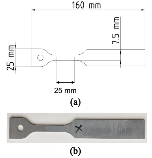
Fig. 3—(a) Schematic diagram showing the dimensions of specimen
used for uniaxial tensile tests, and (b) An actual tensile specimen
machined from the as-cast part with 2-mm wall thickness.
Fig. 3—(a) Schematic diagram showing the dimensions of specimen
used for uniaxial tensile tests, and (b) An actual tensile specimen
machined from the as-cast part with 2-mm wall thickness.