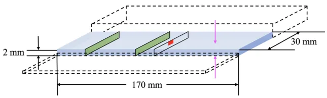
Fig. 2—Graphical representation of an as-cast part of 2-mm wall thickness, with green and red colored boxes, respectively, indicating the locations used for microscopic analysis and hardness measurements. The pink arrows indicate the two casting surfaces on which the skin layer is supposedly formed (Color figure online).
Fig. 2—Graphical representation of an as-cast part of 2-mm wall thickness, with green and red colored boxes, respectively, indicating the locations used for microscopic analysis and hardness measurements. The pink arrows indicate the two casting surfaces on which the skin layer is supposedly formed (Color figure online).