This technical summary is based on the academic paper "Thermal Control of High-Powered Desktop and Laptop Microprocessors Using Two-Phase and Single-Phase Loop Cooling Systems" published by Randeep Singh in RMIT University (March 2006). It was analyzed and summarized for HPDC experts by CASTMAN experts with the help of LLM AI such as Gemini, ChatGPT, and Grok.
Keywords
- Primary Keyword: Two-Phase Loop Cooling Systems
- Secondary Keywords: Miniature Loop Heat Pipe (mLHP), microprocessor thermal control, single-phase liquid cooling, microchannel heat sink, sintered porous heat sink, capillary pumped loop (CPL), high heat flux cooling
Executive Summary
- The Challenge: The rapid increase in power density of microprocessors in desktops (80-130W) and laptops (25-50W) has pushed conventional cooling technologies like heat pipes and vapor chambers to their limits. Future electronic systems require more advanced thermal management solutions.
- The Method: This research developed and characterized different thermal designs based on both passive two-phase heat transfer (miniature Loop Heat Pipes, mLHPs) and active single-phase liquid cooling (using microchannel and sintered porous heat sinks).
- The Key Breakthrough: Two-phase cooling units proved to be a highly reliable passive solution for high heat fluxes (up to 70 W/cm²) in compact devices like laptops. For extreme heat fluxes (up to 400 W/cm²) in high-powered desktops, active single-phase liquid cooling systems are more effective but structurally complex.
- The Bottom Line: The choice between passive two-phase and active single-phase cooling is not one-size-fits-all; it depends critically on the application's specific heat flux, space constraints, and reliability requirements.
The Challenge: Why This Research Matters for HPDC Professionals
As processing power in electronics skyrockets, so does the waste heat generated. At present, CPUs in desktops and servers release 80 to 130 W, while notebook computers dissipate 25 to 50 W—and these numbers are only climbing. This thermal challenge is compounded by the shrinking footprint of the chipsets themselves, leading to extreme heat fluxes that can exceed 70 W/cm².
For engineers and designers, maintaining chip surface temperatures below 100 °C is a non-negotiable requirement for reliability. It's expected that conventional cooling methods, including standard heat pipes and vapor chambers, will not meet the future thermal demands of these high-powered systems. This creates a critical need for innovative, reliable, and powerful thermal control technologies that can be integrated into compact electronic devices. This research tackles this exact problem by exploring the next generation of both passive and active loop cooling systems.
The Approach: Unpacking the Methodology
To find a solution to this pressing thermal challenge, the researcher developed and characterized multiple advanced cooling prototypes based on two distinct principles:
- Two-Phase Cooling Systems (Passive): The study focused on developing and testing investigative prototypes of passively operating miniature Loop Heat Pipes (mLHPs). These devices use the capillary forces in a wick structure to circulate a working fluid, transferring heat via an evaporation-condensation cycle without any active pump. Prototypes included mLHPs with both flat disk-shaped and innovative thin rectangular evaporators.
- Single-Phase Liquid Cooling Systems (Active): To handle even higher, more concentrated heat fluxes, the research explored active liquid cooling. This involved developing heat sinks with innovative microstructures, including microchannels and sintered microporous media. These systems use a pump to actively circulate a liquid coolant, offering the potential for much higher heat removal capacity.
By building, testing, and comparing these distinct systems, the study provides a comprehensive analysis of their performance, capabilities, and suitability for different high-density microprocessor applications.
The Breakthrough: Key Findings & Data
This extensive investigation yielded critical insights into the performance and application of next-generation cooling technologies.
- Finding 1: Two-Phase mLHPs Excel in Compact, High-Flux Applications. The developed miniature Loop Heat Pipe (mLHP) with a flat disk-shaped evaporator proved capable of removing heat fluxes as high as 70 W/cm² and transferring the heat over 150 mm, making it a highly reliable and versatile solution for laptop microprocessors.
- Finding 2: Single-Phase Systems Conquer Extreme Heat Fluxes. For desktop and server applications with extreme power densities, single-phase liquid cooling systems demonstrated superior performance. Heat sinks with microstructures (like microchannels or sintered porous media) were shown to be capable of handling concentrated heat fluxes as high as 400 W/cm².
- Finding 3: A Clear Performance Trade-Off. A comparative study (Chapter 9) revealed a clear distinction: two-phase passive systems are highly reliable and efficient for low-to-moderate high heat fluxes. However, their performance degrades at extreme heat loads where single-phase active systems, despite their complexity and need for a pump, are more effective (see Figure 9.12).
- Finding 4: Evaporator Design is Critical for Miniaturization. The study successfully developed an mLHP with a flat rectangular evaporator only 5 mm thick by relocating the compensation chamber to its sides. While this achieved significant thinning, it came with a minor performance trade-off compared to the 10 mm disk-shaped design, highlighting the critical design considerations in miniaturization (Figure 6.13).
- Finding 5: Material Compatibility and Purity are Paramount. The research confirmed that Non-Condensable Gas (NCG) generation can degrade performance and increase start-up time. Proper cleaning procedures and degassing of the working fluid are essential to ensure long-term, reliable operation (Figure 5.37, Figure 5.41).
Practical Implications for HPDC Products
While this paper focuses on electronics cooling, the principles of advanced thermal management are universally applicable. For engineers working with high-performance components that may be housed in die-cast enclosures, these findings offer valuable insights.
- For Component and System Designers: This research provides a data-driven framework for selecting the right advanced cooling technology. The comparative study in Chapter 9 clearly shows that for high-reliability applications with significant but not extreme heat loads (like laptops or mobile devices), passive two-phase mLHPs are an excellent choice. For systems where maximum heat removal is the priority (like high-performance servers), active single-phase liquid cooling is superior.
- For Quality and Reliability Engineers: The findings on Non-Condensable Gas (NCG) generation (Chapter 5.9) underscore the critical importance of material compatibility and manufacturing cleanliness in any sealed thermal management system. The study shows that even trace impurities can lead to performance degradation over time, a vital lesson for long-life products.
- For R&D and Innovation Teams: The novel design of the 5 mm thick flat rectangular evaporator (Chapter 6) demonstrates a practical path toward miniaturizing powerful thermal solutions. This concept of relocating key components to reduce overall thickness can inspire innovation in integrating thermal management directly into compact product assemblies.
Paper Details
Thermal Control of High-Powered Desktop and Laptop Microprocessors Using Two-Phase and Single-Phase Loop Cooling Systems
1. Overview:
- Title: Thermal Control of High-Powered Desktop and Laptop Microprocessors Using Two-Phase and Single-Phase Loop Cooling Systems
- Author: Randeep Singh
- Year of publication: March 2006
- Journal/academic society of publication: RMIT University (Thesis for Doctor of Philosophy)
- Keywords: two-phase cooling, single-phase cooling, loop heat pipe, microchannel heat sink, sintered porous heat sink, thermal control, microprocessor
2. Abstract:
The development of high-end and compact computers has resulted in a considerable rise in the power dissipation requirements of their microprocessors. At present, the waste heat release by the Central Processing Unit (CPU) of a desktop and server computer is 80 to 130 W and a notebook computer is 25 to 50 W. New systems have already been built with thermal outputs as high as 200 W for desktops and around 70 W for laptops. At the same time, the heating areas of the chipsets have become as small as 1 to 4 cm². This problem is further complicated by both the limited available space and the restriction to maintain the chip surface temperature below 100 ºC. It is expected that conventional two phase technologies like heat pipes and vapour chambers as well as current designs of single phase cooling systems will not be able to meet these future thermal needs of computer systems. With the intention of finding a solution to this problem, different thermal designs based on both two-phase and single-phase heat transfer were developed and characterized for the thermal control of high density microprocessors. In the domain of two phase technology, two investigative prototypes of capillary driven passively operating loop heat pipes with characteristic thickness as small as 5 or 10 mm and capable of dissipating heat fluxes as high as 70 W/cm² were designed and tested. These devices responded very well to the thermal needs of laptop microprocessors. The thermal characteristics of single phase cooling systems were enhanced with the purpose of handling concentrated heat fluxes as high as 400 W/cm². This was made possible by developing heat sinks with innovative microstructures that include microchannels or sintered microporous media. As an outcome of the present research work, it is concluded that two phase cooling units provide a highly reliable thermal solution for the cooling of laptop microprocessors with high heat fluxes and limited available space for accommodating thermal devices. However the thermal performance of the passive devices is limited at very high magnitudes of heat flux. Therefore cooling technology needs to be further explored for the effective management of future high powered electronic systems. Liquid cooling systems can handle extremely high heat fluxes very effectively but they are structurally complex and unreliable due to the requirement for an active component (like a pump) in the system that also requires power for its operation.
3. Introduction:
Thermal control is a generic need of electronic equipment. As detailed in Chapter 1 of the paper, the increasing power dissipation from microprocessors in both laptops and desktops has made traditional cooling methods insufficient. While simple devices rely on natural convection, high-performance computers require advanced thermal solutions. Heat pipes and vapor chambers have been effective, but future power densities demand more capable systems. This has led to the development of innovative two-phase loop heat pipes and enhanced single-phase liquid cooling systems with microstructures, which this research investigates to address the thermal needs of next-generation computers.
4. Summary of the study:
Background of the research topic:
The research addresses the critical challenge of thermal management in modern computers, where increasing microprocessor power density and shrinking size demand solutions beyond conventional air cooling, heat pipes, and vapor chambers.
Status of previous research:
Previous research has established Loop Heat Pipes (LHPs) and Capillary Pumped Loops (CPLs) as robust two-phase systems, primarily for aerospace, and single-phase liquid cooling with microchannels for high-heat-flux applications. However, miniaturized, cost-effective versions for commercial electronics, particularly comparing their performance under similar constraints, required further investigation.
Purpose of the study:
The main objective was to investigate, design, and develop different thermal solutions based on both two-phase and single-phase cooling to manage the high heat fluxes of laptop and desktop microprocessors. This included developing miniature LHP (mLHP) prototypes for laptops and microstructural heat sinks for desktops, and comparing their performance.
Core study:
The core of the study involved the design, fabrication, and experimental testing of two main types of cooling systems:
- Two-phase miniature Loop Heat Pipes (mLHPs) with different flat evaporator designs (10 mm disk and 5 mm rectangular).
- Single-phase liquid cooling systems using a microchannel heat sink and a sintered porous heat sink.
A comparative study was then conducted to evaluate the performance of a two-phase heat pipe module against a single-phase microchannel system for both single and multiple heat sources.
5. Research Methodology
Research Design:
The research was designed as a series of experimental investigations. Prototypes of each cooling system (mLHP with disk evaporator, mLHP with rectangular evaporator, microchannel heat sink, sintered porous heat sink) were designed and fabricated. A theoretical model for the LHP was also developed for performance prediction.
Data Collection and Analysis Methods:
Experimental test beds were constructed for each prototype. Data was collected using T-Type thermocouples at various points, pressure transducers, and digital wattmeters to control and measure heat load. Data acquisition systems recorded temperatures every 5-10 seconds. Thermal performance was analyzed by calculating key metrics like evaporator temperature, thermal resistance (evaporator, total), and heat transfer coefficients as a function of heat load and coolant flow rate.
Research Topics and Scope:
The research covered several key topics:
- Design and characterization of two-phase mLHPs for laptop cooling (up to 70 W).
- Design and characterization of single-phase liquid cooling systems for desktop cooling (up to 200 W, >400 W/cm²).
- Analysis of startup phenomena, fluid inventory effects, tilt effects, and non-condensable gas (NCG) generation in mLHPs.
- Direct performance comparison of two-phase vs. single-phase cooling for single and multiple heat sources.
6. Key Results:
Key Results:
- Miniature Loop Heat Pipes (mLHPs) are an effective and reliable passive technology for cooling high heat flux chipsets (up to 70 W/cm²) in laptops.
- Liquid cooling with microstructures (microchannels, sintered porous wicks) is a viable approach for extreme heat fluxes (tested up to 408 W/cm²) in high-powered desktop systems.
- Two-phase capillary-driven systems are more reliable due to the absence of active components (pumps), but single-phase systems provide better thermal control for ultra-high heat fluxes.
- Downscaling the thickness of an mLHP evaporator (from 10 mm to 5 mm) is possible with novel design concepts, such as relocating the compensation chamber.
- The operational characteristics of mLHPs are highly dependent on wick properties (material, pore size, porosity) and fluid charge. Biporous wicks show better performance than monoporous wicks.
- The thermal performance of a microchannel heat sink was found to be superior to that of a sintered porous heat sink in terms of both thermal resistance and pressure drop.
Figure Name List:
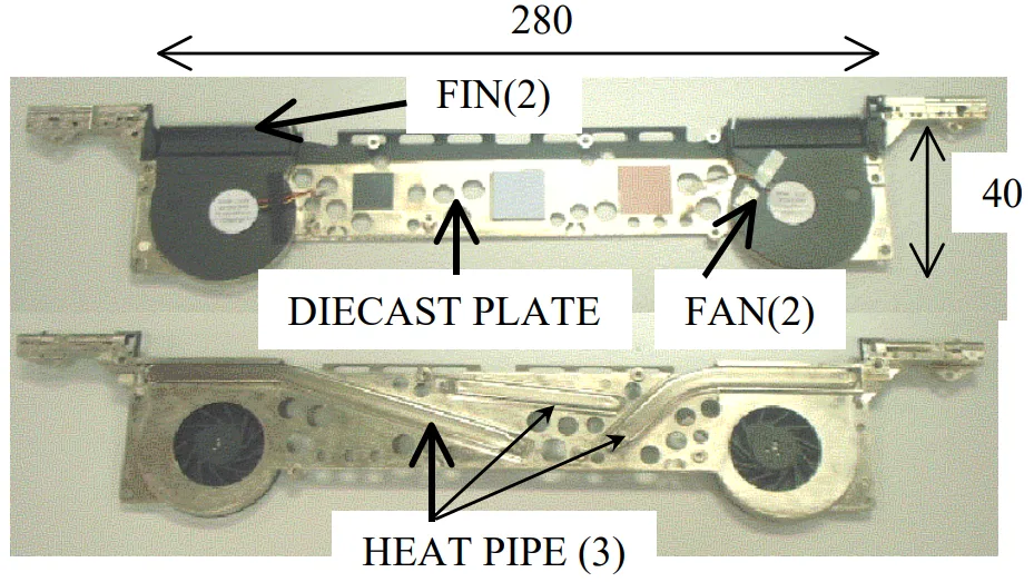
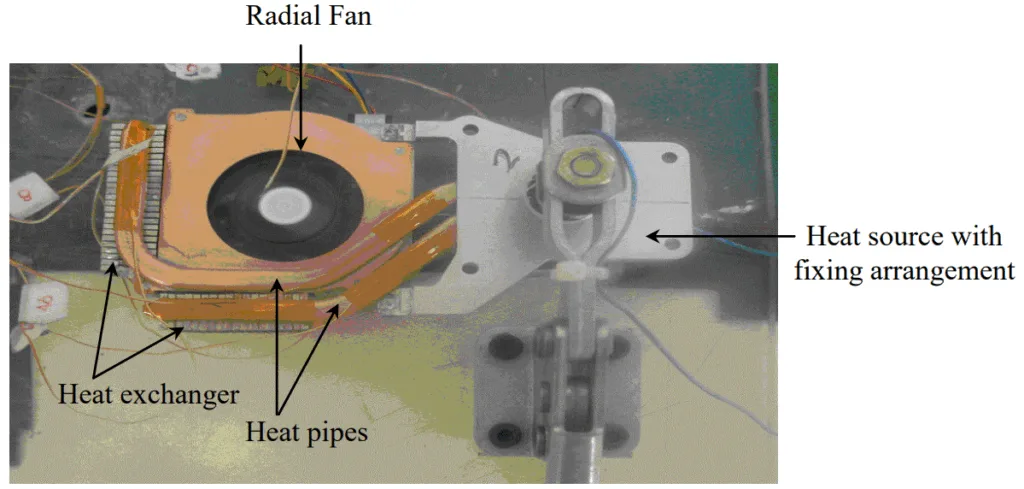
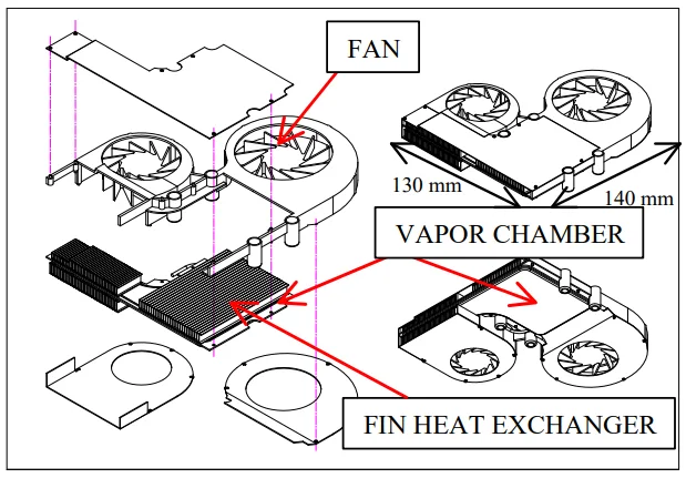
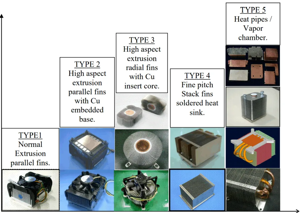
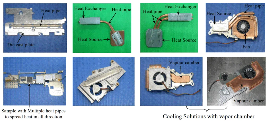
- Figure 1.1 Trends in Thermal Solutions for Laptop PCs
- Figure 1.2 Hybrid thermal control system for laptop microprocessors.
- Figure 1.3 Remote Heat Exchanger for cooling laptop microprocessors.
- Figure 1.4 Different designs of vapour chamber used for laptop cooling
- Figure 1.5 Thermal control system with vapour chamber for laptop cooling
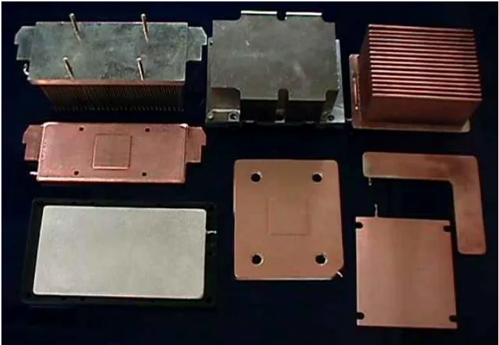
- Figure 1.6 Different Types of Thermal Solution for Desktop Computer Cooling
- Figure 1.7 Thermal Solution Trends
- Figure 2.1 Conventional Capillary Driven Heat Pipe
- Figure 2.2 Arterial Heat Pipes
- Figure 2.3 Separated lines heat pipe
- Figure 2.4 Loop Scheme
- Figure 2.5 Loop Heat Pipe (LHP)
- Figure 2.6 Capillary Pumped Loop (CPL)
- Figure 2.7 Schematic of Loop Heat Pipe
- Figure 2.8 Scheme of organisation of evaporation zone by the principle of an inverted meniscus
- Figure 2.9 Available cooling space inside the laptop computer
- Figure 2.10 Different variants of LHP condenser
- Figure 2.11 Schematic of a Microchannel Heat Sink
- Figure 2.12 Schematic of a Sintered Porous Heat Sink
- Figure 3.1 LHP schematic (Ref: Maydanik & Fershtater, 1997)
- Figure 3.2 P-T diagram of the LHP working cycle
- Figure 3.3 Schematic of the miniature LHP showing various control volumes for the energy balance
- Figure 3.4 Energy Balance inside Control Volume 1
- Figure 3.5 Energy Balance inside Control Volume 2
- Figure 3.6 Energy Balance inside Control Volume 3
- Figure 3.7 Schematics of the LHP condenser
- Figure 3.8 Thermal circuit diagram for the mLHP showing thermal resistances of different components
- Figure 4.1 Prototype of Miniature Loop Heat Pipe (mLHP) showing the different components
- Figure 4.2 Exploded view of the capillary evaporator showing the different parts
- Figure 4.3 mLHP Evaporator
- Figure 4.4 Details of Vapour removal channels
- Figure 4.5 Details of Fin-and-Tube Condenser
- Figure 4.6 Charging procedure for mLHP
- Figure 4.7 Schematic of the experimental prototype and test layout for the mLHP
- Figure 5.1 Start-up of the mLHP at 15W input power
- Figure 5.2 Heat load dependence of the evaporator surface temperature
- Figure 5.3 Heat transfer coefficient versus applied heat load
- Figure 5.4 Heat pipe thermal resistance versus applied heat load
- Figure 5.5 Total thermal resistance versus applied heat load
- Figure 5.6 Evaporator thermal resistance versus applied heat load
- Figure 5.7 Start-up failure due to leakage in external sealing
- Figure 5.8 Start-up failure due to internal leakage
- Figure 5.9 Start-up failure of the mLHP under 30% fluid charge
- Figure 5.10 Start-up failure of the mLHP under 40% fluid charge
- Figure 5.11 Start-up trend shown by the mLHP when the liquid-vapour interface is already present in the evaporator before heat load is applied
- Figure 5.12 Start-up trend shown by the mLHP when in the pre start state the vapour removal channels are completely flooded with liquid
- Figure 5.13 Start-up trend shown by the mLHP when in the pre start state insufficient fluid inventory is present in the compensation chamber
- Figure 5.14 Comparison of theoretically predicted and experimentally determined results for the mLHP design with sintered nickel capillary structure
- Figure 5.15 Comparison of predicted and experimental results for the mLHP design with sintered copper capillary structure
- Figure 5.16 Effect of the fluid charge on the evaporator wall temperature for the given range of applied heat loads
- Figure 5.17 Test setup to measure the thermal performance of the mLHP at different tilt angles
- Figure 5.18 Effect of the tilt angle on the thermal performance of the mLHP
- Figure 5.19 Change in the fluid distribution inside the compensation chamber with the increase in the tilt angle
- Figure 5.20 Start-up of the mLHP with uniform heating of the evaporator active face at input power of 20 W
- Figure 5.21 Start-up of the mLHP with non-uniformly heating of the evaporator active face at input power of 20 W
- Figure 5.22 Thermal performance (evaporator wall temperature versus applied heat load) of mLHP for uniform as well as non uniform heating modes
- Figure 5.23 Evaporator thermal resistance versus applied heat load for uniform and non uniform heating modes
- Figure 5.24 Heat pipe thermal resistance versus applied heat load for uniform and non-uniform heating modes
- Figure 5.25 Total thermal resistance versus applied heat load for uniform and non uniform heating modes
- Figure 5.26 Heat load dependence of the evaporator wall temperature with nickel and copper wicks
- Figure 5.27 Heat load dependence of the evaporator wall temperature for mLHP with nickel and copper wicks
- Figure 5.28 Evaporator thermal resistance versus applied heat load for mLHP with nickel and copper wicks
- Figure 5.29 Heat load dependence of the evaporator wall temperature for monoporous copper wicks with different physical properties
- Figure 5.30 Structure of biporous wick
- Figure 5.31 Combined Copper wick showing monoporous and biporous layers
- Figure 5.32 Heat load dependence of the evaporator wall temperature for mLHP with monoporous and combined wick
- Figure 5.33 Evaporator temperature trend with respect to the applied heat load for the number of trial runs made on the mLHP over a period of time
- Figure 5.34 Change in the absolute pressure inside the loop due to the generation of NCG over a period of time.
- Figure 5.35 Oxidation of the container and wick material due to the reaction and absorption of the NCG gas accumulated inside the compensation chamber
- Figure 5.36 Temperature profile on the surface of the compensation chamber taken with the help of five K-Type thermocouples
- Figure 5.37 Start-up trend shown by the mLHP with and without NCG
- Figure 5.38 Design arrangement for purging the NCG from the mLHP system
- Figure 5.39 Experimental Set-up for purging the NCG from the mLHP
- Figure 5.40 Operational Characteristics of the mLHP before and after purging procedure
- Figure 5.41 Operational Characteristics of the mLHP before and after degassing procedure
- Figure 6.1 Schematic of Flat Rectangular Evaporator mLHP showing the components
- Figure 6.2 Exploded view of the capillary evaporator showing the parts
- Figure 6.3 mLHP Evaporator
- Figure 6.4 Plan view of the evaporator body
- Figure 6.5 Details of vapour removal channels
- Figure 6.6 Details of Fin-and-Tube Condenser
- Figure 6.7 Experimental set up for testing the flat rectangular evaporator mLHP
- Figure 6.8 Start-up of rectangular evaporator mLHP at 20 W input power
- Figure 6.9 Heat load dependence of the rectangular evaporator mLHP evaporator temperature
- Figure 6.10 Evaporator thermal resistance versus applied heat load for the rectangular evaporator mLHP
- Figure 6.11 Total thermal resistance versus applied heat load for the rectangular evaporator mLHP
- Figure 6.12 Comparison of the heater interface temperature for the disk shaped evaporator mLHP and rectangular evaporator mLHP at the same range of input heat loads.
- Figure 6.13 Comparison of the evaporator temperature for the disk shaped evaporator mLHP and rectangular evaporator mLHP at the same range of input heat loads.
- Figure 6.14 Cross section of the disk shaped evaporator showing internal structures and directions of the liquid and heat flows relative to each other
- Figure 6.15 Cross section of the rectangular shaped evaporator showing internal structures and directions of the liquid and heat flows relative to each other
- Figure 6.16 Evaporator thermal resistance for the disk shaped evaporator mLHP and rectangular evaporator mLHP at the same range of input heat loads.
- Figure 6.17 Total thermal resistance for the mLHP with disk shaped evaporator and rectangular evaporator at the same range of input heat loads.
- Figure 7.1 Layout of the Microchannel heat sink assembly
- Figure 7.2 Schematic of the Microchannels
- Figure 7.3 Internal details and liquid flow path inside the microchannel heat sink
- Figure 7.4 Experimental Setup to test microchannel heat sink
- Figure 7.5 Cross sectional view of the microchannel heat sink and distributed finned heat exchanger showing the fluid flow pattern inside the cooling unit.
- Figure 7.6 Test bed for the Microchannel heat sink
- Figure 7.7 Experimental setup for open loop system
- Figure 7.8 Experimental setup for closed loop system
- Figure 7.9 Test facility for the heat sink showing the location of the thermocouples on the microchannel heat sink
- Figure 7.10 Test facility for the heat sink showing the location of the thermocouples on the Finned Heat Exchanger
- Figure 7.11 Heat load dependence of the Interface temperature of the microchannel heat sink with the 11mm x 13mm heat source
- Figure 7.12 Cold plate thermal resistance and total thermal resistance of the microchannel heat sink with respect to the applied heat load using 11mmx13mm heat source
- Figure 7.13 Heat load dependence of the Interface temperature of the microchannel heat sink with different heater sizes (7 x7 mm², 11 x13 mm²)
- Figure 7.14 Variation of the cold plate thermal resistance of the microchannel heat sink with the applied heat load with different heater sizes (7 x7 mm², 11 x13 mm²)
- Figure 7.15 Variation of the total thermal resistance of the microchannel heat sink with the applied heat load for different heater sizes (7 x7 mm², 11 x13 mm²)
- Figure 7.16 Heat load dependence of the interface temperature for the microchannel heat sink for different flow rates
- Figure 7.17 Cold plate thermal resistance of the microchannel heat sink with respect to the applied heat load for different flow rates
- Figure 7.18 Heat transfer coefficient of the microchannel heat sink with respect to the applied heat load for different flow rates
- Figure 7.19 Variation of the heat transfer coefficient with applied heat load: Comparison of the experimental and the predicted results by using different entry length conditions and flow regimes
- Figure 7.20 Variation of the Nusselt number with Reynolds number: Comparison of the experimental and the predicted results by using different entry length conditions and flow regimes
- Figure 8.1 Layout of Sintered Porous Heat Sink
- Figure 8.2 Internal structure of the Sintered Porous Heat Sink
- Figure 8.3 Picture of the cooling section showing the Porous Insert inside the machined rectangular channel
- Figure 8.4 Exploded View of the Sintered Porous Heat Sink
- Figure 8.5 Sample of the sintered porous material at different magnifications showing rounded irregular copper granular particles fused together as the result of the sintering process
- Figure 8.6 Cross Sectional view of the sintered porous heat sink showing the liquid flow pattern inside the cooling section
- Figure 8.7 Experimental Setup of the Sintered Porous Heat Sink
- Figure 8.8 Test Facility for the Sintered Porous Heat Sink showing the location of the thermocouple points
- Figure 8.9 Pressure drop versus flow rate for the Sintered Porous Heat Sink
- Figure 8.10 Interface temperature versus flow rate for applied heat load of 100 W
- Figure 8.11 Relationship between the interface temperature and the applied heat load for different flow rates
- Figure 8.12 Heat transfer coefficient versus applied heat load for different flow rates
- Figure 8.13 Cold plate thermal resistance versus applied heat load for different flow rates
- Figure 8.14 Cold plate thermal resistance versus flow rate for applied heat load of 100 W
- Figure 8.15 Comparison of the cold plate thermal resistance for Microchannel and Sintered Porous Heat Sinks
- Figure 8.16 Comparison of the overall heat transfer coefficient (based on the heater active face area) for Microchannel and Sintered Porous Heat Sink
- Figure 8.17 Comparison of the pressure drop across the heat sink versus flow rate for Microchannel and Sintered Porous Heat Sink
- Figure 9.1 Heat Pipe Cooling Unit
- Figure 9.2 Heat Pipe Module
- Figure 9.3 Cross Section of the Heat Pipe showing internal configuration
- Figure 9. 4 Bottom perspective view of the Heat Pipe cooling unit showing the evaporator sections and related components.
- Figure 9.5 Side View of the Heat Pipe Cooling Unit showing the heater locations
- Figure 9.6 Liquid Cooling Unit
- Figure 9.7 Microchannel for CPU size heater
- Figure 9.8 Microchannel for MPU/GPU size heater
- Figure 9.9 Bottom perspective view of the liquid cooling unit showing the evaporator sections and related components.
- Figure 9.10 Side View of the liquid cooling unit showing the heater locations
- Figure 9.11 Perspective view of the liquid cooling unit showing the fluid flow pattern inside the loop and location of each microchannel section.
- Figure 9.12 Heat load dependence of the interface temperature for the heat pipe and liquid cooling unit
- Figure 9.13 Total thermal resistance versus applied heat load for the heat pipe and liquid cooling unit
- Figure 9.14 CPU Interface temperature versus CPU applied heat load for different power inputs to the GPU and MPU units (Heat pipe cooling unit)
- Figure 9.15 CPU Interface temperature versus CPU applied heat load for different power inputs to the GPU and MPU units (Liquid cooling unit)
- Figure 9.16 CPU Interface temperature versus CPU applied heat load for different power inputs to the GPU and MPU units : Comparison between heat pipe cooling unit and liquid cooling unit
- Figure B.1 Schematic of CPL
- Figure B.2 Layout of the Capillary Pumped Loop Experimental Model
- Figure B.3 Design and detail of the axially grooved evaporator tube
- Figure B.4 Exploded view of the Capillary Evaporator
- Figure B.5 Schematic of CPL Evaporator
- Figure B.6 Heat and Fluid flow inside the capillary evaporator
- Figure B.7 CPL Experimental Setup
- Figure B.8 CPL Test Bed
- Figure B.9 Start up of CPL at 50 W heat load
- Figure B.10 Start-up of CPL at 100 W heat load
- Figure B.11 Evaporator temperature versus applied heat load for low heat inputs
- Figure B.12 Evaporator temperature versus applied heat load for high heat inputs
- Figure B.13 Variation of the evaporator thermal resistance with the applied heat load
- Figure B.14 Variation of the total thermal resistance with the applied heat load
- Figure C.1 Apparatus to measure permeability using a constant pressure reservoir
- Figure C.2 Apparatus to measure permeability using pressure tuning arrangement
- Figure C.3 Variation of specific permeability and mass flow rate with applied pressure across the porous structure
- Figure C.4 U-Tube bubble point testing system
- Figure C.5 Mechanism of bubble formation
- Figure C.6 Modified form of bubble point testing system to measure the largest pore size in the fine pored wicks
- Figure C.7 Method to determine mean pore size of the wick sample
- Figure C.8 Comparison of porosity of the UHMW Polyethylene wick as determine by different methods
- Figure C.9 Test sample showing the location of the heater and the finned heat exchanger
- Figure C.10 Experimental setup for measuring the effective thermal conductivity of the copper wick saturated with water
- Figure C.11 Effective thermal conductivity versus applied heat load for the copper wick saturated with water
7. Conclusion:
(Based on Chapter 10: Conclusions and Recommendations)
This research provides an exhaustive investigation into advanced cooling systems for high-powered microprocessors. The conclusions are clear:
- Two-phase systems (mLHPs) are highly effective and reliable for thermal management of devices like laptops, capable of handling high heat fluxes (up to 70 W/cm²) in a passive, compact form factor.
- Single-phase liquid cooling systems with microstructures are a viable, though more complex, approach for the thermal control of next-generation, high-powered desktop microprocessors facing extreme heat fluxes (approaching 400 W/cm²).
- While capillary-driven two-phase systems offer greater reliability due to the absence of active pumps, single-phase systems provide a better solution for ultra-high heat fluxes due to higher achievable mass flow rates. Ultimately, a trade-off exists between the reliability and passivity of two-phase systems and the extreme performance of active single-phase systems.
8. References:
- Adams, TM, Abdel-Khalik, SI, Jeter, SM & Qureshi, ZH 1998, ‘An Experimental Investigation of Single-Phase Forced Convection in Microchannels’, International Journal of Heat Mass Transfer, Vol. 41, pp. 851-857.
- Adkins, DR & Moss, T 1990, ‘Measuring Flow Properties of Wicks for Heat Pipe Solar Receivers’, in Proceedings of the ASME International Solar Energy Conference, Miami, Florida, April 1-4, 1990.
- Alexander, EG 1972, ‘Structure-Property Relationships in Heat Pipe Wicking Materials’ PhD Dissertation, North Caroline State University, Department of Chemical Engineering, 1972.
- … (A full list of references is available in the original thesis, pages 220-227) …
- Zhmud, BV, Tiberg, F & Hallstensson, K 2000, ‘Dynamics of Capillary Rise, Journal of Colloid and Interface Science, Vol. 228, pp. 263-269.
Expert Q&A: Your Top Questions Answered
Q1: Which system is better for cooling high-powered electronics: two-phase or single-phase?
A1: The study concludes there is no single "better" system; it depends on the application. Two-phase systems like mLHPs are highly reliable, passive (no pump), and excellent for high heat fluxes in compact devices like laptops. Single-phase liquid cooling is active (requires a pump) but is more effective for handling the extreme heat fluxes of high-powered desktops and servers. (Source: Chapter 10, Concluding Remarks).
Q2: What is a miniature Loop Heat Pipe (mLHP) and why is it an important technology?
A2: An mLHP is a passive, two-phase heat transfer device that uses capillary forces in a wick to circulate a fluid and transfer heat. It's an evolution of the traditional heat pipe, designed to handle higher heat loads over longer distances and against gravity. It's important because it offers a highly reliable cooling solution for powerful electronics in very compact spaces where traditional methods are insufficient. (Source: Chapter 2, Introduction and Literature Review).
Q3: How much heat can these advanced systems actually remove?
A3: The two-phase mLHP prototypes were capable of dissipating heat fluxes as high as 70 W/cm². The single-phase cooling systems with microstructures were developed with the purpose of handling concentrated heat fluxes as high as 400 W/cm², demonstrating their suitability for future high-powered systems. (Source: Abstract).
Q4: What were the key design innovations tested for making these cooling systems smaller?
A4: A key innovation was the development of a flat rectangular mLHP evaporator with a thickness of only 5 mm. This was achieved through a novel concept of relocating the compensation chamber from the thickness of the evaporator to its sides, a significant step in miniaturizing powerful passive cooling. (Source: Chapter 6, Chapter 10.2.2).
Q5: The paper mentions Non-Condensable Gas (NCG) as a potential problem. How was this addressed?
A5: The study confirmed that NCGs, which can arise from impurities, degrade performance and increase start-up time. The research showed that NCGs tend to accumulate in the compensation chamber. It was experimentally established that enhancing the fluid charging procedure, specifically by degassing the water before it's introduced into the loop, significantly decreases the extent of NCG generation and improves long-term reliability. (Source: Chapter 5.9.5, Figure 5.41).
Q6: What's the main practical takeaway from this paper for an engineer designing a product with a high-powered microprocessor?
A6: The core takeaway is that as power densities increase beyond the limits of conventional air cooling, advanced loop cooling systems offer viable solutions. The choice between a passive two-phase system (for high reliability and moderate-to-high heat flux) and an active single-phase system (for extreme heat flux) is a critical design decision that must be based on the specific thermal load, space, and reliability requirements of the product. (Source: "Thermal Control of High-Powered Desktop and Laptop Microprocessors Using Two-Phase and Single-Phase Loop Cooling Systems", Concluding Remarks).
Conclusion & Next Steps
This research provides a valuable roadmap for enhancing thermal management in high-performance electronics. The findings offer a clear, data-driven path toward selecting and designing the right cooling architecture—whether passive or active—to improve quality, ensure reliability, and handle the ever-increasing thermal loads of modern microprocessors.
At CASTMAN, we are dedicated to applying the latest industry research to solve our customers' most challenging die casting problems. If the issues of thermal management and component reliability discussed in this paper resonate with your operational goals, contact our engineering team to discuss how our precision components can form the foundation of your advanced thermal solutions.
Copyright
- This material is a paper by "Randeep Singh". Based on "Thermal Control of High-Powered Desktop and Laptop Microprocessors Using Two-Phase and Single-Phase Loop Cooling Systems".
- Source of the paper: The thesis was submitted to RMIT University in March 2006. A public DOI is not available.
This material is for informational purposes only. Unauthorized commercial use is prohibited. Copyright © 2025 CASTMAN. All rights reserved.