This introduction paper is based on the paper "Effect of Shielding Gases on the Wire Arc Additive Manufacturability of 5 Cr – 4 Mo Tool Steel for Die Casting Mold Making" published by "Korean Journal of Metals and Materials".
1. Overview:
- Title: Effect of Shielding Gases on the Wire Arc Additive Manufacturability of 5 Cr – 4 Mo Tool Steel for Die Casting Mold Making
- Author: Jae-Deuk Kim, Jae Won Kim, Joo Yong Cheon, Yang-Do Kim, and Changwook Ji
- Year of publication: 2020
- Journal/academic society of publication: Korean Journal of Metals and Materials (Korean J. Met. Mater.)
- Keywords: GMAW, wire arc additive manufacturing (WAAM), tool steel, shielding gas, die casting mold
2. Abstract:
Generally, molds are fabricated by the machining of massive billets of tool steels, such as AISI4140 or H13, but it has drawbacks, such as a large material loss and long-delivery time. The Wire-Arc Additive Manufacturing (WAAM) process could be an alternative fabrication method. It has the advantages of less material loss, short-delivery time, and the chance to make a reinforced mold using dissimilar materials. 5 Cr – 4 Mo steel wire has high potential to produce molds via the WAAM process. This is a commercial tool steel solid wire initially designed for the repair and modification of tools and molds that has superior hot wear resistance and toughness. However, no study has examined the WAAM of tool steels, even though it has high potential and advantages. Shielding gas has a significant effect on the performance of the WAAM process, which is based on gas metal arc welding (GMAW). Argon (an inert gas) and carbon dioxide (a reactive gas) are generally used for the GMAW of steel alloys, and they are frequently used as mixed gases at various ratios. Shielding gases have a significant influence on the arc stability, weld quality, and formation of weld defects. Therefore, using a proper shielding gas for the material and process is important to sound WAAM performance. This paper discusses the effect of the shielding gas on the additive manufacturability of tool steel, as a first step for the WAAM of die casting molds. The experiments were conducted with two different shielding gases, M21 (Ar + 18% CO2) and C1 (100% CO2). The use of C1 showed neither surface contamination nor internal defects, and resulted in a larger amount of deposition than the M21.
3. Introduction:
Conventional fabrication of die-casting molds from tool steels like AISI 4140 or H13 involves machining massive billets, leading to significant material loss and extended delivery times. Wire-Arc Additive Manufacturing (WAAM), a type of direct energy deposition (DED) AM process, presents an alternative with benefits such as reduced material waste, shorter lead times, high deposition rates, and the ability to use commercial equipment and filler materials. Specifically, 5 Cr – 4 Mo tool steel wire is a promising candidate for WAAM of die-casting molds due to its high heat wear resistance and toughness.
Shielding gas plays a critical role in the GMAW-based WAAM process, protecting the weld pool from atmospheric contamination and influencing arc stability, weld quality, bead geometry, and defect formation. While argon (Ar) and carbon dioxide (CO2) are commonly used for steel alloys, their specific effects on the WAAM of tool steels for die casting molds require investigation.
4. Summary of the study:
Background of the research topic:
The automotive industry's demand for lighter vehicles has increased the use of aluminum die-cast parts, which require molds typically made from tool steels. Traditional mold manufacturing methods are subtractive, resulting in substantial material loss and long production cycles. Additive manufacturing, particularly WAAM, offers a more efficient alternative.
Status of previous research:
While WAAM has been explored for various metal alloys, there is limited research on its application to tool steels for die-casting mold fabrication. The influence of shielding gases, a critical parameter in WAAM, on the manufacturability of 5 Cr – 4 Mo tool steel for this purpose has not been extensively studied.
Purpose of the study:
This study aimed to investigate the effect of two different shielding gases, M21 (Ar + 18% CO2) and C1 (100% CO2), on the additive manufacturability of a commercial 5 Cr – 4 Mo tool steel solid wire deposited on a thick SCM 440 (AISI 4140) substrate using the GMAW-based WAAM process. This serves as an initial step towards developing WAAM for die casting mold production.
Core study:
The core of the study involved a comparative analysis of WAAM deposits produced using M21 (designated UM samples) and C1 (designated UC samples) shielding gases. The investigation focused on:
- Surface characteristics and internal defects of the deposits.
- Geometrical features of single beads and multi-layer deposits (height, width, cross-sectional area).
- Deposition efficiency and overall build characteristics.
- Microstructure and mechanical properties (microhardness, tensile strength) of the AM products.
5. Research Methodology
Research Design:
The study employed an experimental research design. A commercial 5 Cr – 4 Mo tool steel filler wire was deposited on an SCM 440 alloy substrate using a CMT welding machine and a robotic system. Two shielding gases, M21 (Ar + 18% CO2) and C1 (100% CO2), were used under consistent welding parameters (heat input ~600-650 J/mm, CTWD 15 mm). Three types of experiments were conducted: bead-on-plate (BOP) tests, small-scale (3 × 3 stacking) AM, and large-scale two-dimensional AM.
Data Collection and Analysis Methods:
- Visual Inspection: To assess surface conditions, spatter, and weld scale.
- 3D-CT Analysis: To detect internal defects such as porosity.
- Geometrical Analysis: Samples were wire-cut, polished, and etched (Nital and Vilella etchants). Bead dimensions (height, width, penetration depth) and cross-sectional areas were measured using imaging software.
- Microstructural Analysis: Conducted on etched samples.
- Mechanical Testing:
- Micro Vickers hardness tests (0.2 kgf load) were performed on deposited metal and HAZ.
- Tensile shear tests were conducted on large-scale AM samples.
- Fractography analysis was performed using a scanning electron microscope (SEM).
Research Topics and Scope:
The research focused on the influence of M21 and C1 shielding gases on:
- Surface quality and the formation of sessile weld scale.
- Presence and nature of internal defects (porosity).
- Bead geometry and deposition characteristics in single-pass, small-scale multi-layer, and large-scale multi-layer deposits.
- Microstructure, microhardness distribution, and ultimate tensile strength of the WAAM-produced 5 Cr – 4 Mo tool steel.
6. Key Results:
Key Results:
- Surface Condition and Internal Defects:
- Sessile weld scale, leading to surface contamination, was observed on all UM (M21 gas) products but not on UC (C1 gas) products. This was attributed to the different gas compositions.
- Internal defects in the form of porosity (less than 1 mm in size) were found in UM products (both small-scale and large-scale AM), likely due to surface contamination from the sessile weld scale and potentially different gas flow dynamics. UC products were free from such internal defects.
- Bead Geometry and Deposition:
- In BOP tests, small-scale AM, and large-scale AM, the UC samples consistently showed a higher bead height and a larger weld bead cross-sectional area (approx. 19% larger in BOP and small-scale AM) compared to UM samples, while bead width and penetration depth were similar.
- The C1 gas (UC) resulted in a more convex bead shape and a higher deposition amount per pass, which is advantageous for WAAM by potentially reducing the number of passes and overall manufacturing time. For instance, large-scale AM required 57 passes for UC versus 64 passes for UM to achieve a similar height.
- While UM showed slightly better build regularity in small-scale AM, UC's higher deposition led to some unevenness at the sides due to material flow, though not constituting a critical defect like side collapse.
- Microstructure and Microhardness:
- The dominant microstructural constituents (martensite and bainite in the weld, with some allotriomorphic ferrite) and overall microhardness values of the deposited metal were similar for both UM (avg. 620±51 HV) and UC (avg. 600±66 HV) products.
- The HAZ near the substrate showed a mixture of martensite/bainite, pearlite, and ferrite, with hardness values of 350±73 HV (UM) and 383±84 HV (UC), compared to the substrate hardness of 202 HV.
- The shielding gas did not appear to have a critical impact on the dominant microstructural constituents or microhardness from a macroscopic viewpoint.
- Tensile Strength and Fracture Behavior:
- The ultimate tensile strength (UTS) of UC products (1450 MPa) was significantly higher (by more than 200 MPa) than that of UM products (1270 MPa).
- Fractography revealed a dimpled transgranular fracture with porosities and a larger amount of spherical precipitates (likely MX carbides) in UM samples. These features acted as crack initiation sites and contributed to the lower UTS.
- UC samples showed clear cleavage fracture surfaces with almost no precipitates. The lower number of precipitates in UC was attributed to different thermal histories and cooling rates influenced by the C1 shielding gas, which led to higher heat intensity.
- Overall Shielding Gas Effect:
- The C1 (100% CO2) shielding gas resulted in superior WAAM performance for the 5 Cr – 4 Mo tool steel in terms of defect-free deposits (no surface contamination or internal porosity) and higher deposition rates.
- Shielding gas significantly influenced the formation of precipitates at a microscopic level, impacting tensile strength, while having a lesser effect on the bulk microstructure and hardness.
Figure Name List:

- Fig. 1. Equipment setup for the experiment.
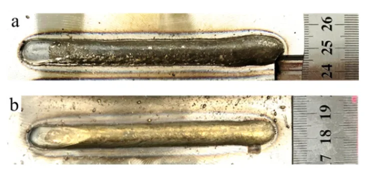
- Fig. 2. Top-view of the BOP test result; a) UM, b) UC.
- Fig. 3. Cross-sectional macro images of the UM and UC with the highlight along the outer line. The yellow and red color highlights represent the UM and UC, respectively.
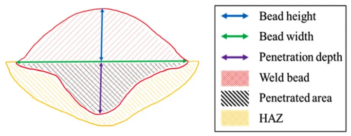
- Fig. 4. Schematic diagram of the measured length and cross-sectional area of the weld bead.
- Fig. 5. Plot of the measured length and cross-sectional area of each sample. The length and area values are shown as columns and marks, respectively.
- Fig. 6. Images of small-scale additive manufactured products; a) and b) are the top-view of the UM and UC, and c) and d) are the cross-section of the UM and UC, respectively. a-b) and c-d) are taken at the same magnification, respectively.
- Fig. 7. Result of 3D-CT analysis; a)UM, b)UC
- Fig. 8. (a) Cross-sectional macro images of the UM and UC with the highlight along the outer line. The yellow in the left and red in right highlights represent the UM and UC, respectively. (b) The image delineates the merging of the actual borderline of the UM and UC to compare the cross-sectional areas. (c) The images are shown the merging of the actual borderline of BOP on the small-scale AM to match-up.
- Fig. 9. Micro Vickers hardness of the UM and UC. The test of the UM and UC was conducted as shown in a), c), e), and b), e), f), respectively. This was done along both the horizontal and vertical directions and are plotted, as shown in c), d), and e) f), respectively. Each point in the plots is the averaged value of 3 points with a distance of 1 mm.
- Fig. 10. Microstructure images of the UM and UC. The pure weld and HAZ in the last pass where it does not affected by subsequent pass are shown in (a) and (b), respectively. The HAZ near the substrate is shown in (a) and (b), respectively. And the substrate is shown in (e). The (a) and (b) correspond to the green arrows, and (c) and (d) to the purple arrows in Fig. 9, respectively. (x 500).
- Fig. 11. Front-view of the large-scale additive manufactured products on the substrate. a) UM and b) UC were additively manufactured five products per each at a length and height of 125 mm.
- Fig. 12. 3D-CT analysis results. Porosities captured by the 3D-CT analysis in the UM products in a) and b). The red arrows are indicating the porosities, which are the internal defect. None of the volumetric defect was captured in UC as shown in c).
- Fig. 13. Ultimate tensile strength values of UM and UC with the standard deviation.
- Fig. 14. Fracture surfaces of UM (a - c) and UC (d and e). The magnification of images are varied.
7. Conclusion:
This study investigated the additive manufacturability of a commercial 5 Cr – 4 Mo tool steel wire using the GMAW-based WAAM process with two different shielding gases, M21 (Ar + 18% CO2) and C1 (100% CO2). The key conclusions are:
i) Sessile weld scale was observed on all UM (M21 gas) products, leading to surface contamination that adversely affected product performance. UC (C1 gas) products were free from this scale.
ii) Internal defects (porosity) were found only in UM products, attributed to surface contamination by the sessile weld scale.
iii) UC products consistently exhibited a higher bead height and larger cross-sectional area compared to UM products, indicating a higher deposition rate which is advantageous for reducing manufacturing time and effort in AM.
iv) While the main microstructural constituents and micromechanical properties (hardness) of UM and UC products were similar, the UTS of UC products was significantly higher (by over 200 MPa). The lower UTS in UM products was attributed to the presence of porosities and a larger amount of precipitates.
v) The choice of shielding gas has a significant effect on the depletion of alloying elements and the formation of precipitates from a microscopic viewpoint, thereby impacting tensile strength, while having a limited impact on the dominant microstructural constituents from a macroscopic viewpoint. The C1 (100% CO2) shielding gas demonstrated superior performance for WAAM of the 5 Cr – 4 Mo tool steel.
8. References:
- [1] T. D. Ngo, A. Kashani, G. Imbalzano, Kate T. Q. Nguyen, and D. Hui, Compos. B. Eng. 143, 172 (2018).
- [2] W. E Frazier, J. Mater. Eng. Perform. 23, 1917 (2014).
- [3] P. Kah and J. Martikainen, Int. J. Adv. Manuf. Technol. 64, 1411 (2013).
- [4] H. S. Jeong, J. Weld. Join. 19, 1 (2001).
- [5] ISO 14175:2008, Welding consumables-Gases and gas mixtures for fusion welding and allied processes (2008).
- [6] I. Pires, T. Rosado, A. Costa, and L. Quintino, In Proceedings of the 10th International Aachen Welding Conference, Aachen, Germany (2007).
- [7] P. Kikani, J. Mater. Metall. Eng. 6, 6 (2019).
- [8] M. Tanaka, S. Tashiro, T. Satoh, A. B. Murphy, and J. J. Lowke, Sci. Technol. Weld. Join. 13, 225 (2008).
- [9] R. Killing, S. H. Hwang, J. P. Jung, and Y. J. Park, J. Weld. Join. 12, 51 (1994).
- [10] KOBE STEEL, LTD., Weld Imperfections and Preventive Measures, pp.1-19, KOBE STEEL, LTD., Japan (2015).
- [11] F. C. Campbell, Inspection of Metals: Understanding the Basics, pp. 411-417, ASM International, Ohio (2013).
- [12] T. Prabakaran, M. Prabhakar, and P. Sathiya, Surf. Rev. Lett. 24, 1750069-1 (2017).
- [13] M. Terner, T. A. Bayarsaikhan, H. U. Hong, and J. H. Lee, J. Weld. Join. 35, 16 (2017).
- [14] T. Rodrigues, V. Duarte, R. M. Miranda, T. G. Santos, and J. P. Oliveira, Materials 12, 1121 (2019).
- [15] Y. Luo, J. Li, J. Xu, L. Zhu, J. Han, and C. Zhang, J. Mater. Process. Tech. 259, 353 (2018).
- [16] J. S. Seo, H. S. Ryoo, and H. J. Kim, J. Weld. Join. 30, 300 (2012).
- [17] J. Dong, Y. He, G. Song, J. Jung, and K. Shin, Mater. Technol. 27, 70 (2012).
- [18] G. Golański and P. Wieczorek, Arch. Foundry Eng. 9, 97 (2009).
- [19] S. Lynch, Eng. Fail. Anal. 100, 329 (2019).
- [20] P. Michaud, D. Delagnes, P. Lamesle, M. H. Mathon, and C. Levaillant, Acta Mater. 55, 4877 (2007).
- [21] B. Moon, J. Lee, N. Kang, T. Lee, W. Jung, C. Park, and K. Cho, Korean J. Met. Mater. 57, 422 (2019).
- [22] M. Kim, Y. Kang, N. Kim, S. Lee, S. Song, and N. Kang, Korean J. Met. Mater. 57, 430 (2019).
- [23] X. He, C. Hu, Z. Wang, H. Zhao, X. Wei, and H. Dong, Mater. Res. Express 7, 036511(2020).
9. Copyright:
- This material is a paper by "Jae-Deuk Kim, Jae Won Kim, Joo Yong Cheon, Yang-Do Kim, and Changwook Ji". Based on "Effect of Shielding Gases on the Wire Arc Additive Manufacturability of 5 Cr – 4 Mo Tool Steel for Die Casting Mold Making".
- Source of the paper: https://doi.org/10.3365/KJMM.2020.58.12.852
This material is summarized based on the above paper, and unauthorized use for commercial purposes is prohibited.
Copyright © 2025 CASTMAN. All rights reserved.