This introduction paper is based on the paper "Fatigue assessment of hot-chamber zinc die-casting components in relation to the casting process and casting process simulation" published by "Fraunhofer Verlag".
1. Overview:
- Title: Fatigue assessment of hot-chamber zinc die-casting components in relation to the casting process and casting process simulation
- Author: Christian Pittel, Axel Kansy, Christos Mangos, Saliha Gündogan
- Year of publication: 2025
- Journal/academic society of publication: Proceedings of the 3rd Congress for Intelligent Combining of Design, Casting, Computer Simulation, Checking and Cyclic Behaviour for Efficient Cast Components, March 5th-6th, 2025, Darmstadt (InCeight Casting C⁸)
- Keywords: die casting, hot chamber, zinc, Z410, casting parameters, casting process simulation, cyclic material behavior.
2. Abstract:
Zinc die-casting alloys are used in many industries for static or low-cycle applications due to their high strength and surface quality. The hot chamber die-casting process generally has very short cycle times which go hand in hand with high productivity. Compared to aluminum, zinc die-casting alloys have a low melting point and can be cast with significantly thinner walls while maintaining a nearly finished surface (“near net shape”) and high dimensional accuracy. This reduces energy consumption in the process, increases die lifetime and contributes to an overall reduction in CO2 equivalents.
However, zinc die-casting alloys are rarely used for components under high cyclic loading, as there is a lack of fatigue data and fatigue assessment methods to describe the cyclical behavior of these materials. Up to now, no scientific research has been done into the cyclic material behavior especially when the samples are influenced by casting parameters. To provide a baseline for a fatigue assessment concept, the cyclic material behavior of samples made from Z410 was investigated and correlated with the local microstructure. A design concept was derived by linking the data from the cyclic analyses with the process parameters during the casting process, the local conditions and solidification effects caused by the casting process and the microstructure.
To validate the fatigue assessment concept, components were cast with variations in die temperature and gate velocity. Furthermore, components from different positions within the die were selected to account for the influence of flow length as an additional factor. Stress-controlled fatigue tests were performed to determine the fatigue strength of the cast components. In conclusion, the determined fatigue strength of the components were compared with the allowable loadings, which were estimated using the fatigue assessment concept.
3. Introduction:
Zinc die casting alloys [1] are used in many industrial sectors for quasi-static or low-cycle applications due to their high surface and component quality. The hot chamber die casting process is of particular importance due to their extremely short cycle times and high productivity. When comparing zinc die casting alloys for example with aluminum the low melting point and the possibility of a significantly thinnerwalled casting with simultaneously high surface qualities and dimensional accuracy are particularly noteworthy. This enables a lower energy consumption in the process, increases die lifetimes and contributes to a reduction in CO2 emissions. This paper aims to investigate the fatigue behavior of zinc diecasting alloys, specifically the Z410 alloy, under varying casting process parameters.
However, zinc die casting alloys are rarely used for components subjected to high cyclic stresses, as there is a lack of data and design methods for describing the cyclic behavior of the material. There are no results available to describe the cyclic material behavior, especially considering the microstructure and the process parameters. Investigations found in the literature [2, 3, 4, 5] do not provide enough details in the documentation of the test procedures and the evaluation methods used. Common design guidelines, such as the FKM guideline [6], do not contain any parameters for zinc die casting. Furthermore, such guidelines are usually based on the tensile strength of the material.
This approach is not suitable for zinc die casting, as the tensile strength cannot be determined from the component, and therefore the transferability of results is not guaranteed. To address the identified gaps in fatigue data and assessment methods, the following section outlines the design of experiments conducted to evaluate the cyclic material behavior of the Z410 alloy.
4. Summary of the study:
Background of the research topic:
Zinc die-casting alloys, particularly Z410 processed via hot chamber die casting, offer advantages like high strength, surface quality, productivity, thin-wall capability, dimensional accuracy, reduced energy consumption, and increased die life compared to aluminum. These benefits contribute to lower CO2 emissions.
Status of previous research:
Despite their advantages, zinc die-casting alloys are infrequently used for components under high cyclic loading. There is a significant lack of fatigue data and established fatigue assessment methodologies, especially those considering the influence of microstructure and casting process parameters. Existing literature [2, 3, 4, 5] lacks sufficient detail on test procedures and evaluation methods. Standard design guidelines, like the FKM guideline [6], do not include parameters for zinc die casting, and traditional approaches based on tensile strength are unsuitable due to the difficulty in determining component tensile strength and ensuring result transferability.
Purpose of the study:
The primary objective was to establish a baseline for a fatigue assessment concept applicable to Z410 hot-chamber die-cast components. This involved investigating the cyclic material behavior, correlating it with the local microstructure, and developing a design concept. The concept aims to link cyclic material data with casting process parameters, local casting conditions, solidification effects, and the resulting microstructure. A further goal was to validate this fatigue assessment concept through component testing under varied casting conditions.
Core study:
The core of the study involved a comprehensive experimental and numerical investigation:
- Material Characterization: The cyclic material behavior of Z410 alloy was determined using unnotched and notched specimens under varying conditions (wall thickness, die temperature, gating speed). Microstructure was evaluated using casting process simulation (MAGMASOFT®) and metallographic analysis. Quasi-static tensile tests were performed for comparison.
- Fatigue Testing: Both strain-controlled (Low Cycle Fatigue - LCF) and stress-controlled (High Cycle Fatigue - HCF) tests were conducted on specimens (near-net-shape and machined from plates) and a validation component (zinc die-cast coupling plate). Different stress ratios (R = -1, R = 0) were used.
- Process Simulation: Solidification and mold filling simulations were performed using MAGMASOFT® to analyze the influence of process parameters (die temperature, gating speed, wall thickness, Frech Dosing System - FDS) on melt temperature at end of fill and cooling rates.
- Fatigue Assessment Concept Development: A concept was developed incorporating:
- The P_RAM damage parameter to account for mean stress influence.
- Statistical size effect based on highly stressed volume (HSV_90%).
- Geometrical size effect (notch effect) quantified by the support factor (n_st) derived from the stress gradient (G_σ) and Weibull coefficient (k_st).
- Technological size effect and surface condition influence, represented by a factor K_CS derived from casting simulation parameters (temperature at end of filling, cooling rate) using multiple linear regression.
- Consideration of survival probability using the f_2.5% factor.
- Validation: The developed fatigue assessment concept was validated by comparing predicted fatigue life/strength with experimental results from component tests conducted under different casting conditions (die temperature, FDS usage, cavity position).
5. Research Methodology
Research Design:
The study employed a combined experimental and numerical research design. A Design of Experiments (DoE) approach guided the investigation, systematically varying key casting process parameters (wall thickness, die temperature, gating speed, Frech Dosing System (FDS) usage, die cavity position) for both specimen-level characterization and component-level validation. The core methodology involved determining the cyclic material properties of Z410, correlating these with microstructure and process simulation results, developing a multi-parameter fatigue assessment concept, and validating this concept against component fatigue tests.
Data Collection and Analysis Methods:
- Material Production: Specimens and components were produced using a Frech DAW125E hot chamber die casting machine.
- Mechanical Testing:
- Fatigue tests: Stress-controlled tests (R=-1, R=0) on electrical resonance testing rigs (F_max = 5 kN, f = 56-81 Hz) for HCF regime (N > 5·10⁴ cycles, N_G = 10⁷ cycles). Strain-controlled tests on a servo-hydraulic rig (F_max = 25 kN, f = 0.1-25.0 Hz) for LCF regime and cyclic stress-strain curve determination. Maximum likelihood method [10] used for S-N curve evaluation.
- Quasi-static tests: Tensile tests according to [9] on a Schenck RSA 100 machine.
- Strain Measurement: Strain gauges used for experimental strain analysis on components.
- Simulation:
- Casting Process: Solidification and mold filling simulation using MAGMASOFT® software to determine temperature at end of filling and cooling rates under various process conditions.
- FE Analysis: Used to calculate design-related parameters (notch factors K_t, highly stressed volume HSV_90%, stress gradient G_σ) for specimens and components. Linear-elastic analysis for component stress determination. Analytical determination of local elastic-plastic loading using Neuber [26] and Masing [27] modifications.
- Microstructural Analysis: Metallographic cross-sections and Scanning Electron Microscopy (SEM) for microstructure documentation and fractography.
- Fatigue Assessment Modeling: P_RAM damage parameter [17, 18, 19] for mean stress. Statistical size effect (n_st) based on HSV_90% and Weibull coefficient k_st [6, 19, 23, 24]. Technological size/surface factor (K_CS) derived via multiple linear regression correlating fatigue strength reduction with simulation outputs (Temp. end of fill, Cooling rate). Survival probability factor f_2.5% based on scatter band [19, 25].
Research Topics and Scope:
The research focused on the fatigue behavior of hot-chamber die-cast zinc alloy Z410 components. Key topics included:
- Quantification of cyclic material properties (LCF, HCF, mean stress influence).
- Correlation of fatigue behavior with local microstructure and casting process parameters (die temperature, gate velocity, wall thickness, FDS, cavity position).
- Influence of near-surface defects (e.g., cold shuts) and microstructure variations (due to cooling rate) on fatigue strength.
- Development of a fatigue assessment concept incorporating statistical, geometrical, and technological size effects, surface condition, and survival probability.
- Use of casting process simulation (MAGMASOFT®) to predict parameters relevant to fatigue (temperature, cooling rate) and integrate them into the assessment concept.
- Validation of the assessment concept using a generic die-cast component (coupling plate).
The scope was limited to the Z410 alloy, the specific specimen and component geometries tested, and the investigated range of casting parameters.
6. Key Results:
Key Results:
- A baseline fatigue life curve (P_RAM – N curve) was established for near-net-shape Z410 specimens with milled edges for wall thicknesses up to 1.5 mm (Fig. 20). Specimens with 3.0 mm thickness showed significantly lower fatigue strength in the HCF range.
- The mean stress influence was quantified using the P_RAM parameter, resulting in a mean stress sensitivity factor M_a = 0.41 for Z410 (Section 6.1).
- Z410 exhibits high notch sensitivity, comparable to high-strength steels, with a determined Weibull coefficient k_st = 39.2 (Fig. 21-A, Section 6.2). The support effect showed a strong dependence on the stress gradient (Fig. 21-B).
- A parameter K_CS was developed using multiple linear regression (R² = 0.64) to quantify the technological size effect and surface condition influence based on casting simulation results (Temperature at end of filling, Cooling rate). Temperature at end of filling showed the largest influence on fatigue strength reduction (Fig. 23, Fig. 24, Section 6.3).
- A survival probability factor f_2.5% = 0.85 (corresponding to T_σ = 1:1.23) was determined from the baseline scatter band for converting 50% to 97.5% survival probability (Section 6.4).
- Quasi-static tensile strength and elongation showed poor correlation with fatigue strength for Z410 die castings (Fig. 18). While minimum elongation requirements were met, tensile strength values were below standard minimums [1].
- Metallographic and SEM analyses confirmed that near-surface defects (microstructural separation, pores, potential cold shuts) significantly influence fatigue behavior, particularly crack initiation at specimen edges (Fig. 14, Fig. 15). These defects are linked to casting parameters like die temperature and wall thickness (cooling rate).
- The Frech Dosing System (FDS) showed minimal impact on porosity and simulated temperature/cooling rates in the component compared to conventional casting under the tested conditions (Fig. 10-13, Fig. 16).
- Validation tests on the coupling plate component showed consistent experimental fatigue strength across different casting variations (CT-01 to CT-04). However, the developed fatigue assessment concept provided a conservative estimation (predicted 90 MPa vs. experimental 129 MPa at N=10⁷, P_S=50%) (Fig. 28). This discrepancy was partly attributed to uncertainties in casting simulation parameters and potentially the small highly stressed volume (HSV_90%) of the component relative to defect sizes.
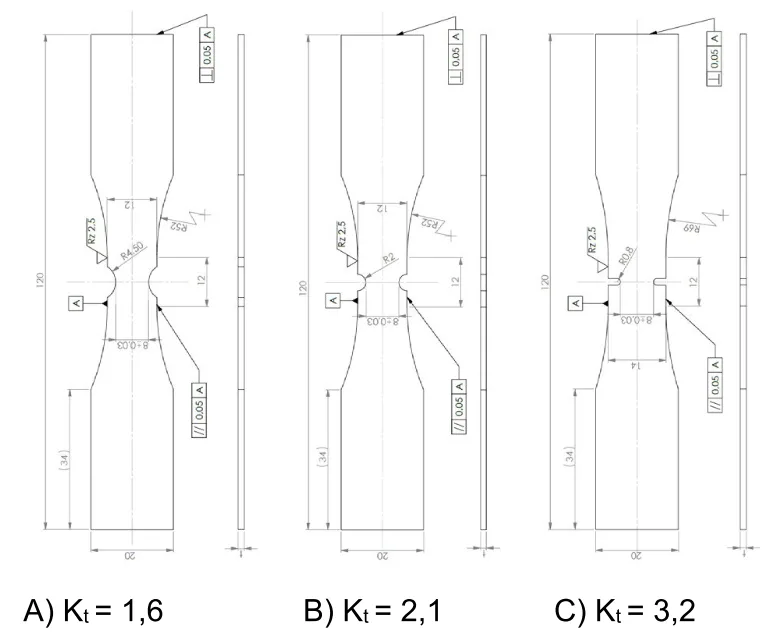
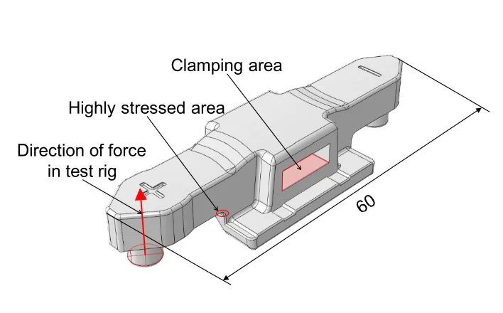
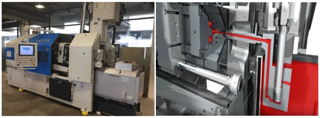
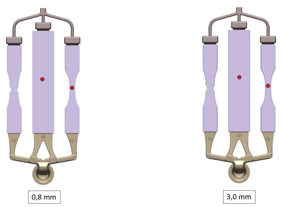
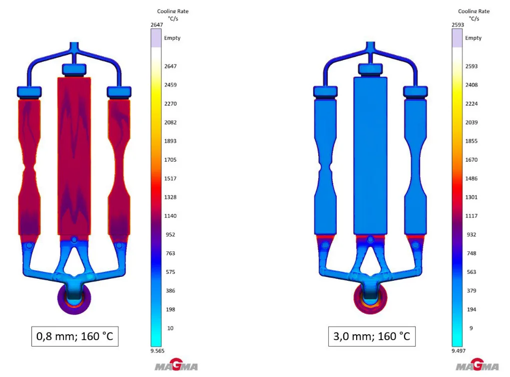
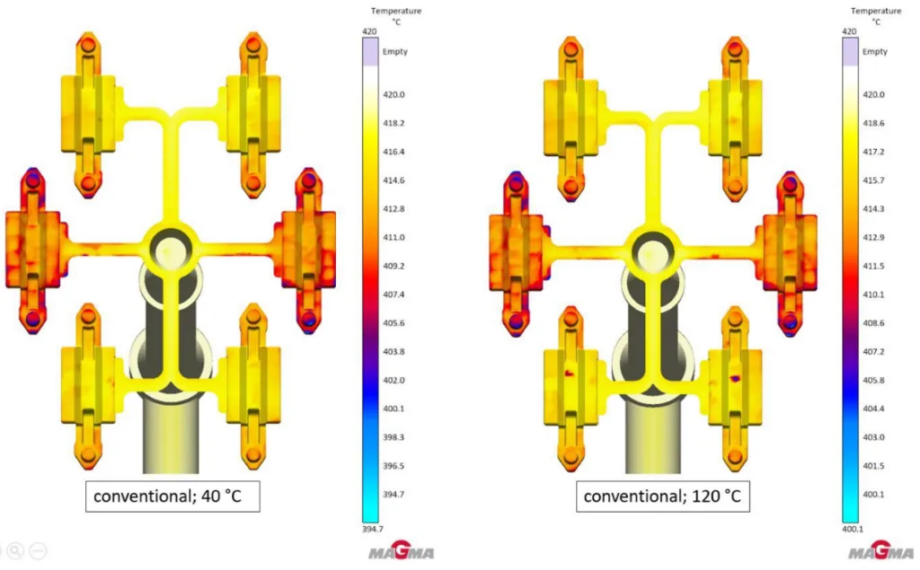
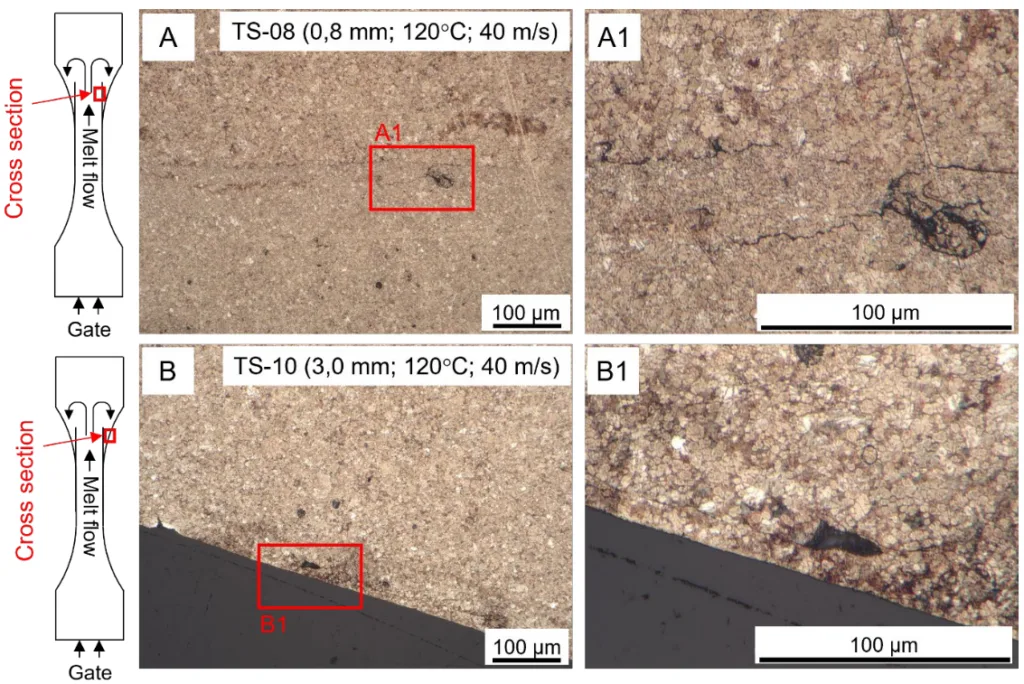
Figure Name List:
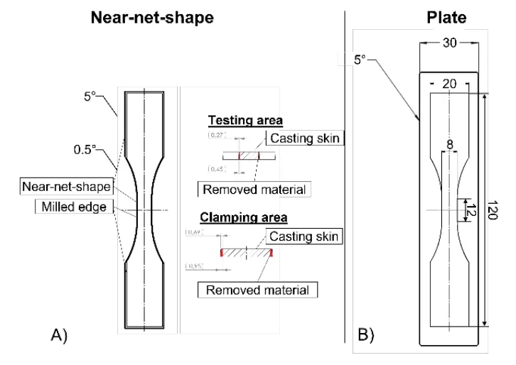
- Fig. 1 Unnotched specimens with three different manufacturing routes; A) Near-net-shape and near-net-shape with milled edges; B) Cast plate with milled edges.
- Fig. 2 Notched specimens with 3 different notch factors.
- Fig. 3 Geometry of the component for validation and schematic representation of forces and boundary conditions of the test rig
- Fig. 4 Frech DAW125E hot chamber die casting machine at Aalen University (left); Schematic layout of a Frech hotchamber machine during the filling process (right). The flow of the melt is marked in red [
- Fig. 5 Overview of the test samples with sprue and overflow system 0.8 mm wall thickness (left) 3.0 mm wall thickness (right). The red points mark the measuring points at which the values for the cooling rate and the temperature at the end of the mold filling were taken from.
- Fig. 6 Temperature at the end of mold filling with 0.8 mm wall thickness(left) and with 3.0 mm wall thickness (right).
- Fig. 7 Cooling rate with 0.8 mm wall thickness (left) compared to the cooling rate with 3.0 mm wall thickness (right).
- Fig. 8 Conventional pouring process (left) compared to the Frech Dosing System (FDS) (right).
- Fig. 9 Conventional casting process (left) compared to the Frech Dosing System (FDS) (right). The red dots mark the measuring point at which the values for the cooling rate and the temperature at the end of the mold filling were taken from.
- Fig. 10 Temperature at the end of mold filling with the conventional pouring process (left) and with FDS (right).
- Fig. 11 Temperature at the end of mold filling conventional at 40 °C mold temperature (left) and at 120 °C mold temperature (right).
- Fig. 12 Cooling rate at 40 °C flow temperature in the mold with the conventional pouring process (left) and with FDS (right).
- Fig. 13 Cooling rate for conventional condition at 40°C mold temperature (left) at 120°C mold temperature (right).
- Fig. 14 Metallographic micrograph in the transition area of 2 representative specimens.
- Fig. 15 SEM image of two specimen fractured in the transition area remote from the gate
- Fig. 16 Metallographic micrograph of the components from CT-01 and CT-03.
- Fig. 17 Metallographic micrograph of the components in the area of the stress hot spot.
- Fig. 18 Results of the tensile tests compared to the fatigue strength of the test series TS-08 to TS-17.
- Fig. 19 Test rigs for the cyclical investigations; A) Electric test-rig for stress-controlled fatigue tests; B) servo-hydraulic test-rig for strain-controlled fatigue tests
- Fig. 20 Baseline P_RAM − N curve of near-net-shaped specimens with milled edges.
- Fig. 21 Investigation regarding influence of the notch factor on fatigue strength.
- Fig. 22 Investigation regarding influence of casting parameters on fatigue strength.
- Fig. 23 Comparison of the casting parameters derived from casting process simulation to the fatigue strength.
- Fig. 24 Comparison of the casting parameters derived from the casting process simulation to the reduction of fatigue strength due to the surface condition.
- Fig. 25 Transformation of the elastic load to elastic-plastic stresses and strains.
- Fig. 26 A) Test rig for component fatigue test; B) Model for the FEM simulation (Visualization with 50x deformation); C) Loading results from the FEM simulation; D) Results of the experimental strain analysis.
- Fig. 27 Design P_RAM − N curve for the component derived from the baseline P_RAM − N curve using the fatigue factors for transferability.
- Fig. 28 Comparison of the design P_RAM − N curve with the experimental results of the component fatigue tests.
7. Conclusion:
[28] describes the tensile strength as a function of the die temperature, the elongation at break and the wall thickness. This correlation can be partially replicated for the quasi-static strength properties. For the fatigue strength, however, there is an opposite behavior depending on the die temperature. Particularly in the case of thin-walled specimens (0.8 mm) where the heat capacity of the melt is smaller, and the cooling rate is higher. This can lead to cold shuts and a resulting reduced surface condition with surface-near defects. This effect can apparently be characterized by the combination of the casting parameters ‘Temperature at end of filling’ and ‘Cooling rate’ from the casting process simulation. The results of the metallographic investigations confirm the assumption that the fatigue behavior of the specimens under cyclic loading is mainly determined by nearsurface defects and the microstructure of the surface layer. This paper highlights the critical role of casting parameters, particularly the temperature at the end of filling and cooling rate, in influencing the fatigue behavior of zinc die-casting alloys. The findings suggest that optimizing these parameters can significantly enhance the fatigue performance of components used in high-stress applications
The introduction of the parameter for considering of the surface condition was able to represent the reduction in the fatigue strength of the specimens. However, the transferability to individual test series with components only worked to a certain degree.
Despite the differences in the parameters from the casting process simulation, the cyclic investigations of the components showed no significant variations in fatigue strength. An explanation could be found in the small HSV_90% of the components in comparison to the defect size, which could mean that the existing defects are not to be found in the region of the HSV_90%. Furthermore, the differences in the parameters of the casting process simulation have not be validated by measurements in the actual casting process, so that there is a fairly large uncertainty on those parameters. Moreover, it was possible to develop design-relevant parameters, such as the support effect and scatter bands for the zinc die-casting alloy. This enables designers and foundries of zinc die-cast components to achieve a reliable estimate of the fatigue strength of such components. Future research should focus on further investigating the fatigue properties of zinc die-casting components and refining the proposed fatigue assessment concept, while also establishing standardized guidelines for the industry.
8. References:
- [1] DIN EN 12844:1998: Zink und Zink-Legierungen – Gussstücke – Spezifikationen; Deutsche Fassung.
- [2] Goodwin, F. E.; Ponikvar, A. L.: Engineering Properties of Zinc Alloys, International Lead Zinc Research Organization, 3rd edition, 1988.
- [3] Szczotka, S.; Klein, F.: Wechselfestigkeitseigenschaften von Zinkdruckgusslegierungen, 1991.
- [4] Goodwin, F. E.; Gagné, M.: Recent Developments in Impact, Flexural and Fatigue Data for Zinc Die Casting Anti-Theft Applications, SAE Technical Paper 2011-01-1088, 2011.
- [5] Leis, W.; Kallien, L. H.: Alterungsvorgänge bei Zinkdruckgusslegierungen, Gießerei 98, 07, S. 26–38, 2011.
- [6] FKM-Richtlinie – Rechnerischer Festigkeitsnachweis für Maschinenbauteile aus Stahl, Eisenguss- und Aluminiumwerkstoffen, 7. Auflage 2020, Forschungskuratorium Maschinenbau (FKM), Frankfurt am Main, 2020.
- [7] Kloos, K.-H.: Einfluss des Oberflächenzustandes und der Probengröße auf die Schwingfestigkeitseigenschaften, VDI-Berichte, 268, Darmstadt, VDI, 63-76, 1976.
- [8] Frech Warmkammer. [Youtube]. Oskar Frech GmbH + Co. KG, 2016; https://www.youtube.com/watch?v=p9uFyI N2fiE.
- [9] DIN EN ISO 6892-1:2019: Metallic materials – Tensile testing – Part 1: Method of test at room temperature; English version EN ISO 68921:2019.
- [10] Störzel, K.; Baumgartner, J.: Statistical Evaluation of Fatigue Tests Using Maximum Likelihood, Materials Testing, De Gruyter, 63 (2021) No. 8, 2021.
- [11] Testing and Documentation Guideline for the Experimental Determination of Mechanical Properties of Steel Sheets for CAE-Calculations, SEP 1240:2006-07, Jul. 2006 [Online]. Available: https://www.beuth.de/en/technical-rule/sep-1240/102501063.
- [12] Coffin, L. A.: A study of the effects of cyclic thermal stresses on a ductile metal, Trans. ASME, vol. 76, no.6, 1954, pp. 931 – 950, DOI: https://doi.org/10.1115/1.4015020.
- [13] Manson, S. S.: Fatigue: A complex subject – some simple approximations, Experimental Mechanics, vol. 5, no. 4, 1965, pp. 193 – 226, 1965, DOI: https://doi.org/10.1007/BF02321056.
- [14] Basquin, O. H.: The exponential law of endurance tests, in Materials Proceedings, no. 10, American Society Test, 1910, p. 625 – 630.
- [15] Morrow, J. D.: Cyclic plastic strain energy and fatigue of metals, American Society for Testing and Materials, ASTM STP 378, 1965, pp. 45 – 87, DOI: https://doi.org/10.1520/STP43764S
- [16] Ramberg, W.; Osgood, W. R.: Description of stress–strain curves by three parameters, NACA, Washington, USA, NACA Technical Report No. 902, 1943.
- [17] Smith, K. N.; Watson, P.; Topper, T. H.: A stress-strain function for the fatigue of metals. Journal of Materials, 5(4):767-778, 1970.
- [18] Bergmann, J.W.: Zur Betriebsfestigkeitsbemessung gekerbter Bauteile auf der Grundlage der örtlichen Beanspruchungen, Dissertation, Heft 37, 1983.
- [19] FKM-Guideline: Richtlinie nichtlinear, 1th. Ed. 2019, ISBN 978-3-8163-0729-7.
- [20] Bleicher, C.; Pittel, C.; Kansy, A.; Niewiadomski, J.; Kaufmann H.: On the strain-life behavior of thick-walled nodular cast iron, Materials Testing, 2024.
- [21] Pittel, C.; Niewiadomski, J., Bleicher, C.: Linking the microstructure with strain-life curves for improved utilization of the lightweight potential of thick-walled nodular cast iron. Journal of Physics: Conference Series. Vol. 2745. No. 1. IOP Publishing, 2024.
- [22] Niewiadomski, J.; Pittel, C.; Kaufmann, H., Berücksichtigung des trilinearen Ansatzes in der gemeinsamen Auswertung kraft- und dehnungsgeregelter Schwingfestigkeitsversuche bei High-Si-GJS, Tagungsband Werkstoffprüfungstagung, 2023.
- [23] Kuguel, R.: A Relation between theoretical stress concentration factor and fatigue notch factor deduced from the concept of highly stressed volume. ASTM Proceedings, 1961.
- [24] Sonsino, C. M.: Zur Bewertung des Schwingfestigkeitsverhalten von Bauteilen mit Hilfe örtlicher Beanspruchungen. Konstruktion, 45, S. 25 – 33, 1993.
- [25] Sonsino, C. M.: Course of SN-curves especially in the high-cycle fatigue regime with regard to component design and safety. International Journal of Fatigue, Nr. 29, 2007, S. 2246 – 2258.
- [26] Neuber, H.: Theory of stress concentration for shear-strained prismatical bodies with arbitrary nonlinear stress-strain law, J.Appl.Mech. 28 (1961), S. 544/50.
- [27] Masing, G.: Eigenspannungen und Verfestigung beim Messing. Proc. 2nd Int. Congress of Applied Mechanics, Zürich, 332-335, 1926.
- [28] Goodwin; F. E. et al.: The Influence of Casting Process Parameters on the Properties and Microstructures of Zinc Alloys 3 and 5, NADCA Congress and Exposition, Detroit, 1991.
9. Copyright:
- This material is a paper by "Christian Pittel, Axel Kansy, Christos Mangos, Saliha Gündogan". Based on "Fatigue assessment of hot-chamber zinc die-casting components in relation to the casting process and casting process simulation".
- Source of the paper: https://doi.org/10.24406/publica-4153
This material is summarized based on the above paper, and unauthorized use for commercial purposes is prohibited.
Copyright © 2025 CASTMAN. All rights reserved.