This introduction paper is based on the paper "Design of Two-stage Side Core-pulling Injection Mold for Special-shaped Parts with Four Sides and Six Undercuts" published by "CHINA PLASTICS".
1. Overview:
- Title: Design of Two-stage Side Core-pulling Injection Mold for Special-shaped Parts with Four Sides and Six Undercuts
- Author: XIONG Yi1,2, WANG Wei2
- Year of publication: 2021
- Journal/academic society of publication: CHINA PLASTICS, Vol. 35, No. 2
- Keywords: shell; undercut; slider; secondary core-pulling; hydraulic cylinder; spring; delay
2. Abstract:
Aim at the difficulty in the large area of undercut in all four sides of the supporting shell in the mold design, we design a scheme to divide all of the side areas into 6 sliders S₁~S₆ for molding according to the demolding direction. Owing to two sliders on the right side of the product, S₂ and S₃, with inconsistent stripper directions and large molding areas, a two-stage sequential core-pulling mechanism with an inclined guide column + hydraulic cylinder was designed. The left side of the product was formed by slider S₅, and a local round hole was formed by the tunnel slider S₆, which was located in the main slider S₅. When the mold was opened, the core-pulling delay was caused by the gap between the holes of the slider angle pin in the slider S₅. After the core-pulling action was completed by the spring-driven slider S₆, the slider S₅ starts to move. The sequential structure of the spring + slider angle pin simplified the secondary core-pulling mechanism. Finally, a single parting hot runner injection mold was designed with a longitudinal layout of one mold and two cavities, a latent gate feeding, and an oblique pushing out. The lateral movement of all the sliders was completed by a single opening of the mold. The mold has a simple structure with a good stability in operation and a high degree of automation.
3. Introduction:
Undercuts represent a common structural feature in plastic parts. Within injection mold design, mechanisms such as inclined guide pins [2], bent pins [3], inclined sliders [4], lifters [5], and hydraulic systems [6] are typically employed to facilitate the lateral demolding of such features. When a product exhibits multiple undercuts on the same side with inconsistent demolding directions, multiple side core-pulling mechanisms are necessitated to ensure independent movement for each demolding direction. To prevent interference between these movements, the sequence of core-pulling actions must be precisely controlled [7-9]. Previous research [10-13] has explored sequential core-pulling systems, often utilizing combinations of hydraulic cylinders and inclined guide pins, different drive methods, fixed mold ejection strategies, or multiple mold opening stages to achieve the required sequence.
4. Summary of the study:
Background of the research topic:
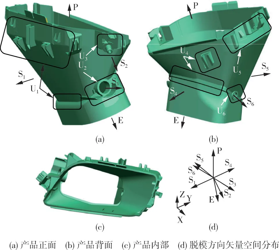
The primary challenge addressed is the design of an injection mold for a complex special-shaped supporting shell part. This complexity arises from the presence of significant undercut features on all four sides of the component, necessitating multiple core-pulling actions from different directions (six in total).
Status of previous research:
Existing approaches for sequential core-pulling, as documented in references [7-14], often involve increasing the number of mold opening steps or designing intricate mechanisms. While effective in resolving sequencing issues, these methods can elevate the structural complexity and manufacturing cost of the mold.
Purpose of the study:
The objective was to develop an efficient and reliable injection mold design for the specific supporting shell part. The design aimed to manage the six distinct undercuts across four sides by implementing sequential core-pulling actions within a single mold opening cycle, utilizing mechanisms that simplify the overall mold structure and enhance operational stability and automation.
Core study:
The core of the research involved a systematic mold design approach. The lateral features of the part were divided among six sliders (S₁ to S₆) based on their respective demolding directions. The central innovation lies in the design of two distinct two-stage sequential core-pulling mechanisms:
- For sliders S₂ and S₃ on the right side, characterized by inconsistent demolding directions and large molding areas, a mechanism combining an inclined guide column and a hydraulic cylinder was implemented for sequential actuation.
- For sliders S₅ and S₆ on the left side, a simplified sequential mechanism was developed. It incorporates a spring-driven tunnel slider (S₆) located within the main slider (S₅). A delay feature, achieved through clearance in the angle pin hole of slider S₅, ensures S₅ moves only after S₆ has completed its core-pulling action initiated by the spring upon release by a wedge lock.
The study also encompassed the design of the overall mold configuration, including a 1-mold 2-cavity longitudinal layout, a single parting surface, a hot runner system transitioning to submarine gates, and an oblique ejection system.
5. Research Methodology
Research Design:
The research employed a structured mold design methodology. This involved detailed analysis of the product geometry, identification of undercuts and determination of optimal demolding directions. Based on this analysis, main and side parting surfaces were designed. The core of the design process focused on conceptualizing and detailing the specialized two-stage sequential core-pulling mechanisms (inclined pin/hydraulic and inclined pin/spring/delay). Standard mold components like the gating system (hot runner to cold runner submarine gates), ejection system (oblique hydraulic ejection), and cooling system were integrated following established design principles. The design process implicitly utilized CAD tools for geometric modeling and mechanism visualization.
Data Collection and Analysis Methods:
The methodology relied primarily on geometric analysis of the plastic part and kinematic analysis of the proposed core-pulling mechanisms. Standard engineering calculations and mold design principles were applied to determine component sizing, material selection (implied), and operational sequencing. Validation of the design was presented through a detailed description of the mold's working principle and the assertion of its simple structure, stable operation, and high automation level, rather than empirical testing data within the paper.
Research Topics and Scope:
The research focused specifically on the design of an injection mold for a particular complex supporting shell. The scope included:
- Management of multiple undercuts on four sides of a part.
- Design and implementation of two distinct two-stage sequential side core-pulling mechanisms.
- Integration of a hot runner gating system with submarine gates for automated production.
- Design of an oblique ejection system suitable for the part geometry.
- Overall mold structure design incorporating these features into a 1-mold 2-cavity configuration.
6. Key Results:
Key Results:
The study resulted in the successful design of a single parting surface, 1-mold 2-cavity injection mold for the complex supporting shell. Key achievements include:
- A systematic division of the part's four-sided undercut features into six sliders (S₁-S₆) based on demolding directions.
- The development and integration of two novel two-stage sequential core-pulling mechanisms:
- An inclined guide column + hydraulic cylinder system actuating sliders S₂ and S₃ sequentially on the right side.
- A simplified system for the left side, employing a spring-driven tunnel slider (S₆) nested within slider S₅, with sequential motion achieved via a delay mechanism incorporated into the inclined guide pin engagement with S₅.
- Implementation of a hot runner system feeding two submarine gates on the part's inner wall for automated operation and reduced waste.
- Incorporation of an oblique ejection system driven by a hydraulic cylinder to demold the part according to its required ejection direction (E).
- The final mold design is characterized by a simplified structure compared to alternatives requiring multiple opening steps, stable operation, and a high degree of automation, achieving all six core-pulling motions within a single mold opening cycle.
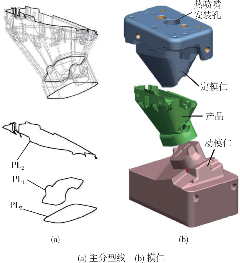
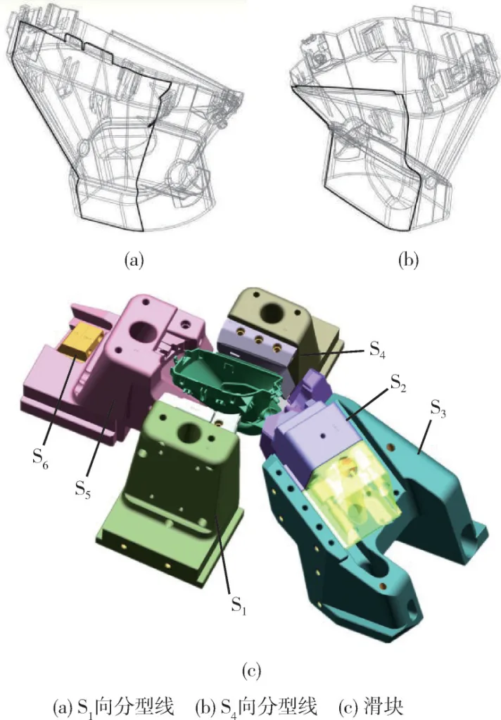
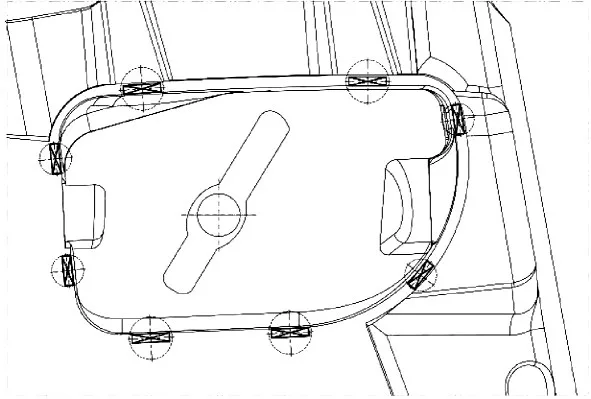
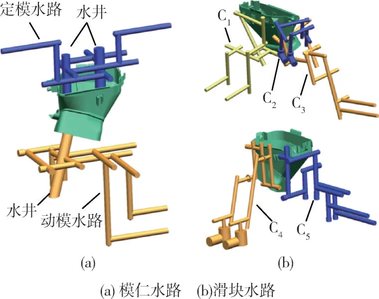
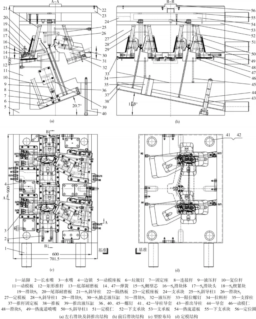
Figure Name List:
- Fig. 1 Structure of the product
- Fig. 2 Main parting of the mold
- Fig. 4 Secondary core-pulling mechanisms of S₂ and S₃
- Fig. 5 Secondary core-pulling mechanisms of S₅ and S₆
- Fig. 6 Gating system
- Fig. 7 Ejection layout
- Fig. 8 The cooling system
- Fig. 9 Structure of the mold
7. Conclusion:
The research successfully addressed the challenges posed by the complex geometry of the supporting shell part, specifically its multiple undercuts on four sides with varying demolding requirements.
(1) By strategically dividing the side features into six distinct sliders (S₁-S₆) according to their demolding directions, the core and cavity structure was simplified, and a basis for sequential core-pulling control was established.
(2) A robust two-stage sequential core-pulling mechanism, combining an inclined guide pin and a hydraulic cylinder, was designed to manage the large, inconsistently directed undercuts formed by sliders S₂ and S₃ on the product's right side.
(3) For the left side, a simplified and effective two-stage mechanism was developed utilizing a spring-driven tunnel slider (S₆) operating within the main slider (S₅). Sequential operation was achieved by incorporating a delay feature (clearance) in the interaction between the inclined guide pin and slider S₅, effectively controlling the timing of the two undercut releases (S₆ then S₅) and simplifying the mechanism structure.
The resulting mold design integrates these solutions, enabling automated production with stable operation.
8. References:
- [1] 齐卫东. 塑料模具设计与制造[M]. 2版. 北京: 高等教育出版社, 2008: 206.
- [2] 郑伶俐, 王 乾. 复杂盖板塑料件模具创新优化设计[J]. 工程塑料应用, 2017, 45(8):84-87. ZHENG L L, WANG Q. Innovative Optimal Design of Mould for Complex Cover Plastic Part [J]. Engineering Plastics Application, 2017, 45(8):84-87.
- [3] 张 强, 李国富, 王正才. 一种斜孔弯销三次抽芯机构的设计[J]. 工程塑料应用, 2017, 45(1):76-79. ZHANG Q, LI G F, WANG Z C. Design of Three Inclined-Hole Angular Cam Core-Pulling Mechanism [J]. Engineering Plastics Application, 2017, 45(1):76-79.
- [4] 韩宝菊. 强力电锤仿生手柄注塑模具设计[J]. 工程塑料应用, 2016, 44(5):60-64,98. HAN B J. Injection Mould Design of Strong Hammer Boionic Handle [J]. Engineering Plastics Application, 2016, 44(5):60-64,98.
- [5] 刘 鑫, 冯 刚. 四面内抽斜顶的圆盖塑料模设计[J]. 塑料工业, 2014, 42(12):49-51. LIU X, FENG G. Four Sides Inner Loose Core and Lifter round Cover Plastic Mould Design [J]. China Plastics Industry, 2014, 42(12):49-51.
- [6] 唐 晖. 一种新型自动自锁液压抽芯机构设计[J]. 塑料科技, 2016, 44(6):76-80. TANG H. Design of a New Type of Automatic Self-Locking Hydraulic Core Pulling Mechanism [J]. Plastics Science and Technology, 2016, 44(6):76-80.
- [7] 陈黎明, 熊建武, 沈忠良. 内壁六面包围框形塑料件脱模机构及模具设计[J]. 工程塑料应用, 2019(9):87-93. CHEN L M, XIONG J W, SHEN Z L. Design of Compound Core-pulling Mechanism and Injection Mold for Six-bread Frame-Shaped Parts with Inner Wall[J]. Engineering Plastics Application, 2019(9):87-93.
- [8] 卞 平, 肖国华. 除尘器手柄特殊滑块抽芯机构及其注塑模具设计[J]. 塑料, 2017, 46(3):69-73,78. BIAN P, XIAO G H. Core Pulling Mechanism and Injection Mold Design of Special Slide Block of Dust Collector [J]. Plastics, 2017, 46(3):69-73,78.
- [9] 陈吉平, 丁智平, 陈宏洲. 一种多元组合抽芯机构注射模设计[J]. 工程塑料应用, 2016, 44(6):76-79. CHEN J P, DING Z P, CHEN H Z. Injection Mould Design for Core-Pulling Mechanism of a Multiple Combination [J]. Engineering Plastics Application, 2016, 44(6):76-79.
- [10] 谭 伟, 程 芳. 具有多抽芯机构的转向器壳体压铸模设计[J]. 特种铸造及有色合金, 2017, 37(8):873-874. TAN W, CHENG F. Design of Die Casting Die for Steering Gear Housing with Multi Core Pulling Mechanism [J]. Special Casting & Nonferrous Alloys, 2017, 37(8):873-874.
- [11] 梅 益, 朱春兰, 宋沛毅, 等. 短固定手柄套多侧向抽芯注塑模具设计[J]. 工程塑料应用, 2018, 46(4):75-79. MEI Y, ZHU C L, SONG P Y, et al. Design of Injection Mould with Multi Side Core-Pulling for Short Fixed Handle Sleeve [J]. Engineering Plastics Application, 2018, 46(4):75-79.
- [12] 高 瑾, 周建军. 微型电机罩壳多类型抽芯机构及前后模顶出注塑模具设计[J]. 塑料工业, 2016, 44(11):83-87. GAO J, ZHOU J J. Design of Injection Mould for Micro Motor Shell with Multi-Type Core Pulling Mechanism and Mould Front-back Ejector Mechanism [J]. China Plastics Industry, 2016, 44(11):83-87.
- [13] 张建卿. 洗涤机屏蔽盖双滑动三次抽芯注塑模脱模机构设计[J]. 塑料科技, 2016, 44(1):87-89. ZHANG J Q. Demoulding Mechanism Design for the Injection Molding of Washing Machine Shield Cover with Thrice Slide-Drawing and Double T-Grooves [J]. Plastics Science and Technology, 2016, 44(1):87-89.
- [14] 刘庆东. 热流道复杂抽芯斜顶出双色注塑模具设计[J]. 中国塑料, 2018, 32(10):138-142. LIU Q D. Design of Bi-Color Inj Ection Mould with Hot Runner, Complex Slides and Inclined Ej Ector[J]. China Plastics, 2018, 32(10):138-142.
- [15] 申开智. 塑料成型模具[M]. 3版. 北京: 中国轻工业出版社, 2013: 79.
9. Copyright:
- This material is a paper by "XIONG Yi, WANG Wei". Based on "Design of Two-stage Side Core-pulling Injection Mold for Special-shaped Parts with Four Sides and Six Undercuts".
- Source of the paper: https://doi.org/10.19491/j.issn.1001-9278.2021.02.017
This material is summarized based on the above paper, and unauthorized use for commercial purposes is prohibited.
Copyright © 2025 CASTMAN. All rights reserved.