This introduction paper is based on the paper "Undercut feature recognition for core and cavity generation" published by "IOP Publishing".
1. Overview:
- Title: Undercut feature recognition for core and cavity generation
- Author: Mursyidah Md Yusof and Mohd Salman Abu Mansor
- Year of publication: 2018
- Journal/academic society of publication: IOP Conference Series: Materials Science and Engineering (Volume 290, Article 012070)
- Keywords: Computer-aided design, undercut, two-plate mould
2. Abstract:
Core and cavity is one of the important components in injection mould where the quality of the final product is mostly dependent on it. In the industry, with years of experience and skill, mould designers commonly use commercial CAD software to design the core and cavity which is time consuming. This paper proposes an algorithm that detect possible undercut features and generate the core and cavity. Two approaches are presented; edge convexity and face connectivity approach. The edge convexity approach is used to recognize undercut features while face connectivity is used to divide the faces into top and bottom region.
3. Introduction:
In the contemporary plastic injection mould industry, mould design predominantly relies on commercial Computer-Aided Design (CAD) software. Operating this software necessitates significant experience, knowledge, and skill from design engineers, potentially leading to inconsistencies due to variations in individual practices. Furthermore, the substantial time investment required for mould design, from initial product conceptualization to manufacturing specifications, contributes significantly to operational costs. Mould design represents a critical phase, defining final product quality and serving as the crucial link for information transfer between product design and manufacturing teams. Research efforts aim to automate the mould design process to enhance consistency, increase productivity, and reduce design cycle time. Within the injection moulding process, undercut feature recognition is a fundamental initial step. This paper builds upon previous research concerning undercut feature recognition (e.g., through holes, pockets) and proposes a novel algorithm for core and cavity generation.
4. Summary of the study:
Background of the research topic:
The design of core and cavity components for injection moulds is conventionally performed using commercial CAD systems by experienced designers. This process is acknowledged as being time-intensive and potentially inconsistent, impacting operational efficiency and costs within the plastic injection moulding industry. Automation is sought to mitigate these challenges.
Status of previous research:
Prior research into automating undercut feature recognition has explored various methodologies. These include graph-based recognition [1], polyhedron face adjacency graph techniques [2], surface visibility analysis [3], feature-based approaches [4,5], volume-based methods [6], and plane projection techniques [7].
Purpose of the study:
This paper aims to propose an algorithm capable of generating core and cavity geometries by first recognizing potential undercut features utilizing an edge convexity approach, and subsequently dividing the part faces into distinct top and bottom regions through a face connectivity approach.
Core study:
The central element of this research is the development and implementation of an algorithm designed to automate undercut detection and core/cavity generation for two-plate injection moulds. The algorithm employs two primary strategies: (1) Edge Convexity Analysis: To identify edges associated with potential undercut features based on the geometric relationship between adjacent faces. (2) Face Connectivity Analysis: To classify and group the remaining faces of the 3D model into 'top' and 'bottom' regions relative to a specified parting direction, which are essential for defining the core and cavity blocks.
5. Research Methodology
Research Design:
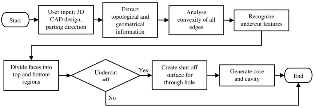
The proposed algorithm follows a structured sequence, as depicted in Figure 1. It begins with user input (3D CAD model and parting direction), proceeds through data extraction, edge convexity analysis, undercut feature recognition, face division into top/bottom regions, and culminates in core and cavity generation (if no undercuts are detected) or system exit (if undercuts are present). The algorithm was implemented using C++ programming language, the ACIS geometric modeling kernel, and solid modeller software.
Data Collection and Analysis Methods:
- Input (Step 1): User provides a 3D CAD part model and specifies the vector of the parting direction (Pd).
- Data Extraction (Step 2): The system extracts topological (vertices, edges, faces) and geometrical information from the input CAD model and stores it.
- Edge Convexity Analysis (Step 3): Each edge is analyzed for convexity. This involves creating temporary extruded bodies from the two faces sharing the edge, extruded along their respective face normals. If the intersection of these bodies results in a solid, the edge is classified as concave (Figure 2 (a)); if the intersection is NULL, the edge is convex. This aligns with the principle that concave edges subtend an angle less than 180° between adjacent faces (Figure 2 (b)).
- Undercut Recognition (Step 4): Faces sharing a concave edge are grouped into a potential undercut face region. This region is then conceptually extruded infinitely along both positive and negative parting directions. If the extruded body intersects other model faces in both directions, it is identified as an undercut feature. If it intersects in only one direction (e.g., positive), it is assigned to the corresponding region (e.g., bottom region).
- Face Division (Step 5): Remaining faces (not part of undercut regions) are grouped into 'top' or 'bottom' regions using a face connectivity approach. A face belongs to the top region if (1) its extrusion along the positive parting direction does not intersect other faces, and (2) it shares an edge with a face already in the top region (this second rule is exempted for the initial face). Similar rules apply for the bottom region using the negative parting direction.
- Undercut Check (Step 6): The algorithm proceeds only if the number of detected undercut features is zero. Otherwise, the system exits.
- Shut-off Surface Creation (Step 7): For parts without undercuts, shut-off surfaces are generated for any existing through holes.
- Core/Cavity Generation (Step 8): The final core and cavity geometries are generated based on the classified top and bottom face regions and any created shut-off surfaces, referencing methodology from [8].
Research Topics and Scope:
The research focuses specifically on the recognition of undercut features in 3D CAD models intended for injection moulding and the subsequent generation of core and cavity geometry for two-plate moulds. The scope is defined by the implemented algorithm utilizing edge convexity and face connectivity approaches. The study evaluates the algorithm's performance on parts with and without undercut features, assuming a single, user-defined parting direction.
6. Key Results:
Key Results:
The algorithm was tested using two distinct 3D CAD inputs, designated Part A and Part B (Figure 3), with the parting direction set along the z-axis for both. Part A (dimensions: 56mm L x 23mm W x 32mm H, 17 faces) contained no undercut features. Part B (dimensions: 160mm L x 140mm W x 10mm H, 29 faces) incorporated undercut features.
Table 1 details the face region classification and edge convexity analysis for selected faces/edges of both parts (convexity/region codes: top=1, bottom=0, none=2, concave=3, convex=4). For Part A, the analysis correctly identified no undercut features. Consequently, the algorithm successfully grouped faces into top (6 faces) and bottom (5 faces) regions (Figure 4) and generated the corresponding core and cavity (Figure 6).
For Part B, the algorithm detected two distinct undercut regions, each comprising 4 faces (Figure 8, Figure 5(a)). As per the algorithm's design (Step 6), the presence of undercuts prevented the generation of core and cavity geometry. However, the system correctly identified and grouped the top region faces (9 faces) and bottom region faces (12 faces) that were not part of the undercuts (Figure 7, Figure 5(b)).
The computational time recorded was 4.21 seconds for Part A and 5.13 seconds for Part B. The difference is attributed to the larger number of faces in Part B requiring processing. The results demonstrate the algorithm's capability to recognize undercuts via edge convexity and partition faces using face connectivity automatically.
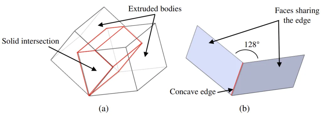
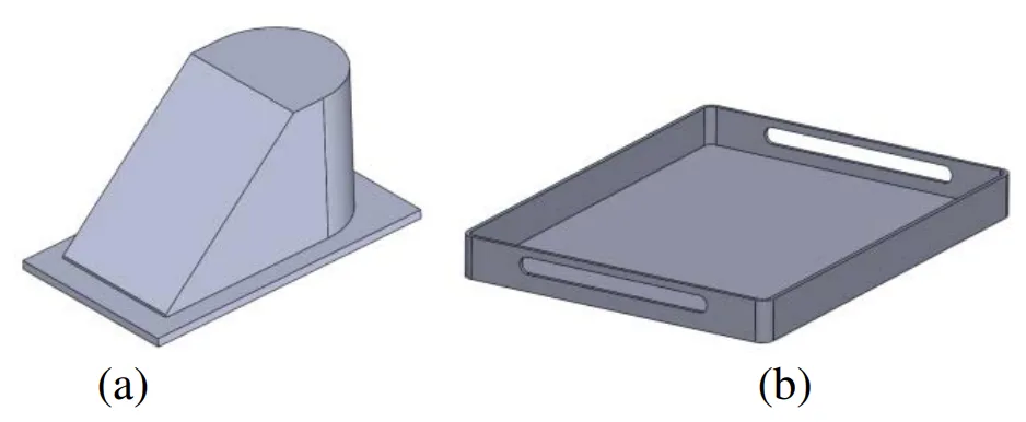
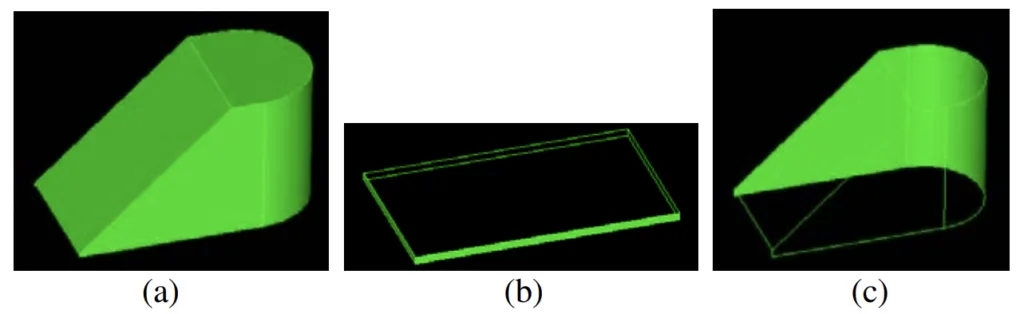
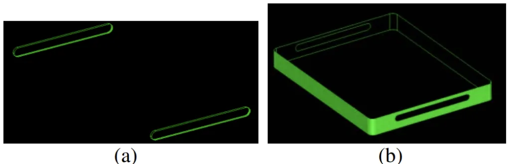
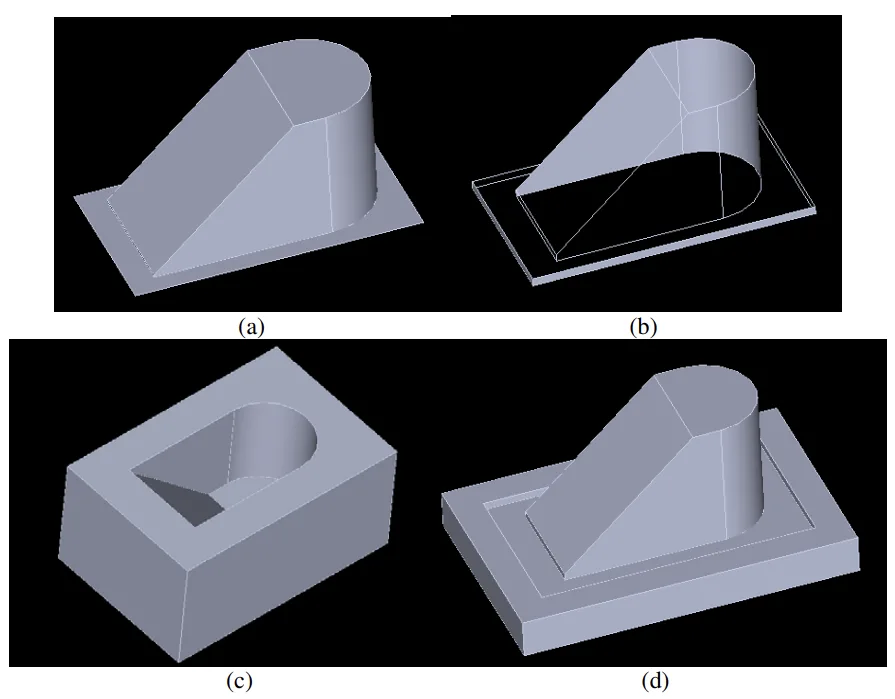
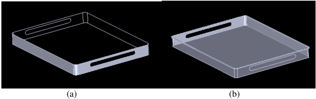
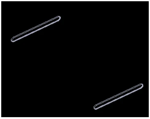
Figure Name List:
- Figure 1. Flowchart of proposed algorithm
- Figure 2. Concave edge (a) intersection of two extruded bodies (b) faces sharing the edge is less than 180°
- Figure 3. 3D CAD inputs (a) Part A (b) Part B
- Figure 4. Part A face regions (a) top region (b) bottom region (c) bottom region
- Figure 5. Part B face regions (a) undercut region (b) bottom region
- Figure 6. Part A output (a) top region (b) bottom region (c) cavity (d) core
- Figure 7. Part B output (a) bottom region (a) top region
- Figure 8. Undercut features of Part B
7. Conclusion:
The presented results validate the efficacy of the proposed algorithm. The edge convexity approach successfully recognized undercut features, while the face connectivity approach effectively divided part faces into top and bottom regions automatically. The system demonstrated its ability to generate core and cavity geometry for parts devoid of undercuts and, crucially, to detect undercut features in parts where they exist, thereby facilitating necessary design adjustments by the user. The computational performance was satisfactory and notably faster compared to manual design using commercial CAD software. Although the current system possesses limitations and is not yet fully robust, future extensions hold the potential to significantly enhance mould designer productivity by reducing design time.
8. References:
- [1] Shao J, Shen G. Research on graph-based recognition of undercut features from molded part. 2nd Int Conf Inf Sci Eng ICISE2010 - Proc 2010:1468–71. doi:10.1109/ICISE.2010.5689693.
- [2] Kumar N, Ranjan R, Tiwari MK. Recognition of undercut features and parting surface of moulded parts using polyhedron face adjacency graph. Int J Adv Manuf Technol 2006;34:47–55. doi:10.1007/s00170-006-0574-7.
- [3] Fu MW, Nee AYC, Fuh JYH. The application of surface visibility and moldability to parting line generation. CAD Comput Aided Des 2002;34:469–80. doi:10.1016/S0010-4485(01)00117-8.
- [4] Bok AY, Abu Mansor MS. Generative regular-freeform surface recognition for generating material removal volume from stock model. Comput Ind Eng 2013;64:162-78. doi:10.1016/j.cie.2012.08.013.
- [5] Zhou ZZZ, Gao SGS, Gu ZGZ, Shi JSJ. A feature-based approach to automatic injection mold generation. Proc Geom Model Process 2000 Theory Appl 2000. doi:10.1109/GMAP.2000.838238.
- [6] Yin, Z., Ding, H. & Xiong, Y., 2001. Virtual prototyping of mold design : geometric mouldability analysis for near-net-shape manufactured parts by feature recognition and geometric reasoning. CAD Computer Aided Design, 33, pp.137-154
- [7] Ran, J.Q. & Fu, M.W., 2010. Design of internal pins in injection mold CAD via the automatic recognition of undercut features. CAD Computer Aided Design, 42, pp.582-597
- [8] Md Yusof M, Abu Mansor MS. Core and Cavity Generation Using Slicing and Boolean-Based Algorithm. Appl Mech Mater 2015;761:175–9. doi:10.4028/www.scientific.net/AMM.761.175.
9. Copyright:
- This material is a paper by "Mursyidah Md Yusof and Mohd Salman Abu Mansor". Based on "Undercut feature recognition for core and cavity generation".
- Source of the paper: https://doi.org/10.1088/1757-899X/290/1/012070
This material is summarized based on the above paper, and unauthorized use for commercial purposes is prohibited.
Copyright © 2025 CASTMAN. All rights reserved.