This article introduces the paper ['Impact behaviour of A356 alloy for low-pressure die casting automotive wheels'] published by ['Journal of Materials Processing Technology'].
1. Overview:
- Title: Impact behaviour of A356 alloy for low-pressure die casting automotive wheels
- Author: Mattia Merlin, Giulio Timelli, Franco Bonollo, Gian Luca Garagnani
- Publication Year: January 2009
- Publishing Journal/Academic Society: Journal of Materials Processing Technology
- Keywords: Aluminium alloys, Impact strength, Castings defects, Microstructure, Numerical simulation
2. Abstracts or Introduction
Instrumented impact strength tests have been carried out on KV sub-size Charpy samples drawn from A356 aluminium alloy 17-in. wheels, produced by a low-pressure die casting. The wheels show different geometry and thermal treatment. In this paper, the effects of microstructure and defects on the impact properties are studied. The results indicate that the impact energy is lower in as-cast wheel than in T6 heat-treated wheels. A finer microstructure always corresponds to higher impact strength, while a direct correlation between the resistance to crack propagation values and secondary dendrite arm spacing (SDAS) exists. Casting defects, revealed by means of X-ray and density measurements techniques, become critical when concentrated around the V-notch, where they reduce the load bearing area of Charpy specimens. The fracture profile and surface of Charpy specimens have been investigated revealing how the crack crosses the interdendritic eutectic region where a significant fraction of cracked eutectic silicon and intermetallic particles is found.
Numerical simulations have been performed to study the filling and solidification behaviour of the alloy of the wheels analysed, in order to predict the final microstructure and shrinkage formation. Solidification times, estimated by means of SDAS measurements and calculated with a numerical simulation approach, show a good correspondence. Critical areas, as concern hot spots and shrinkage porosities, are generally revealed in the zone of the wheels between the spoke and the rim, as well as in the rim area.
3. Research Background:
Background of the Research Topic:
Lowering pollutant emission is a priority objective of international policies together with lowering energy consumption and increasing recycled materials. In the automotive sector, the application of aluminium alloys is considered an economically sustainable innovation. Aluminium-silicon alloys are widely used casting alloys for components with complex shapes, and wheels are a consolidated example. Wheels require a combination of high-quality surface finish, impact and fatigue performance. Low-pressure die casting (LPDC) is the main technology for casting aluminium alloy wheels, offering a good compromise between mechanical properties, high production, cost-effectiveness and design demand.
Status of Existing Research:
Previous research has explored the impact properties of aluminium alloys. Li et al. (2004) analyzed the effect of alloying elements and heat treatments in A319 alloys using instrumented impact tests. Paray et al. (2000) evaluated the absorbed energy of Al-Si foundry alloys. Srivastava et al. (2006) showed the effect of notches on impact values in cast aluminium alloys. Murali et al. (1992) evaluated magnesium content in AlSi7Mg0.3 alloy, and Shivkumar et al. (1994) studied strontium modification and solidification rate in A356-T6 alloys. Zhang et al. (2002) specified the benefits of T6 heat treatment on yield strength and ductility in cast aluminium components, and Cáceres et al. (1995) and Wang and Cáceres (1998) observed the role of inter-particle spacing in crack nucleation and propagation. Cáceres and Selling (1996) quantified the effect of casting defects on mechanical properties.
Necessity of the Research:
While T6 heat treatment benefits are recognized, the additional cost and time are substantial. There is a need to understand the impact properties of LPDC A356 alloy wheels with different geometries and tempers, considering the influence of microstructure and casting defects. Numerical simulation is also needed to predict microstructure and defect formation during the LPDC process.
4. Research Purpose and Research Questions:
Research Purpose:
The aim of this study is to investigate the impact properties of KV sub-size Charpy specimens, drawn from A356 17-in. wheels with different geometry and temper, by means of instrumented Charpy impact testing including discussion of individual energy portions during fracture.
Key Research:
- To correlate microstructural features, such as secondary dendrite arm spacing (SDAS) and eutectic silicon particles, to impact properties (absorbed energy, maximum load, crack nucleation and propagation energy).
- To evaluate the presence of porosity using density measurements and X-ray investigations.
- To utilize numerical simulations to assess the filling and solidification behaviour of the wheels to predict microstructure and shrinkage formation.
Research Hypotheses:
The paper does not explicitly state research hypotheses. However, based on the research purpose and questions, the implicit hypotheses are:
- T6 heat treatment will improve the impact properties of A356 alloy wheels compared to as-cast wheels.
- Finer microstructure (lower SDAS) will lead to higher impact strength.
- Casting defects, particularly porosity, will negatively impact the impact properties.
- Numerical simulation can accurately predict solidification and microstructure, correlating with experimental observations.
5. Research Methodology
Research Design:
The research employed an experimental and numerical simulation approach to investigate the impact behaviour of A356 alloy wheels produced by low-pressure die casting. Instrumented Charpy impact tests were conducted on KV sub-size specimens from wheels with different tempers and geometries. Microstructural analysis, porosity measurements, X-ray investigation, fractography, and numerical simulations were performed to correlate processing, microstructure, defects, and impact properties.
Data Collection Method:
- Instrumented Impact Tests: KV sub-size Charpy impact tests were performed using a Ceast instrumented Charpy pendulum. Total impact energy (Wt), maximum load (Fm), energy at maximum load (Wm), and crack propagation energy (Wp) were measured.
- Microstructural Analysis: Optical microscopy and image analysis were used to observe and quantify microstructures, including SDAS measurements using the linear intercept method. SEM and EDS were used for fractography and analysis of fracture surfaces.
- Porosity Measurement: Density measurements based on Archimedes' principle and X-ray investigations (macro-focus and micro-focus) were used to quantify and localize porosity.
- Numerical Simulation: MAGMASOFT® v.4.2 software with MAGMAlpdc module was used to simulate filling and solidification behaviour. Virtual thermocouples were used to validate temperature profiles.
Analysis Method:
- Correlation Analysis: Statistical correlation was used to analyze the relationship between SDAS, porosity, and impact properties (impact energy, Wp).
- Fractography Analysis: SEM and optical microscopy were used to analyze fracture surfaces and profiles to understand crack initiation and propagation mechanisms in relation to microstructure and defects.
- Numerical Simulation Validation: Simulated solidification times and temperature profiles were compared with SDAS measurements and thermocouple data to validate the numerical model.
Research Subjects and Scope:
The research subjects were three A356 aluminium alloy 17-in. automotive wheels produced by low-pressure die casting (LPDC).
- Wheel-1: 7-spoke, as-cast temper.
- Wheel-2: 5-spoke, T6 heat-treated condition.
- Wheel-3: 5-spoke, T6 heat-treated condition (different geometry and spoke thickness compared to wheel-2).
Samples were drawn from spoke and rim regions of these wheels for testing and analysis.
6. Main Research Results:
Key Research Results:
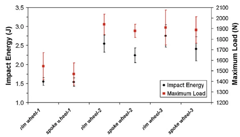
- Impact Energy and Heat Treatment: Impact energy is lower in as-cast wheel-1 compared to T6 heat-treated wheels (wheel-2 and wheel-3). T6 heat treatment increases impact energy by more than 60%.
- Microstructure and Impact Strength: Finer microstructure (lower SDAS) corresponds to higher impact strength. A direct correlation between crack propagation energy (Wp) and SDAS was observed.
- Casting Defects and Impact Properties: Casting defects, particularly porosity, reduce impact properties, especially when concentrated around the V-notch of Charpy specimens, reducing the load-bearing area.
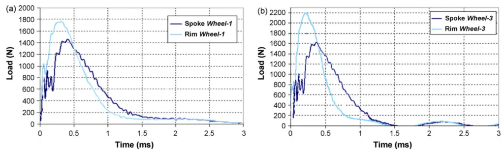
- Fracture Mechanism: Crack propagation follows the interdendritic eutectic region, involving cracked eutectic silicon and intermetallic particles. Fracture surfaces showed transcrystalline and ductile fracture in spoke samples and interdendritic fracture in rim samples.
- Numerical Simulation Validation: Solidification times estimated by SDAS measurements and numerical simulation showed good correspondence. Critical areas for hot spots and shrinkage porosities were identified in the junction zone between spoke and rim and in the rim area.
- Porosity Distribution: Wheel-3 exhibited the highest porosity content, mainly in the spoke region. Porosity distribution was non-homogeneous. Micro-focus X-ray revealed porosity presence around the notch in Charpy samples.
Analysis of presented data:
- Figure 6: Shows that T6 heat treatment significantly increases both impact energy and maximum load compared to as-cast conditions. Rim regions generally exhibit slightly higher impact energy and maximum load than spoke regions within the same wheel temper condition.
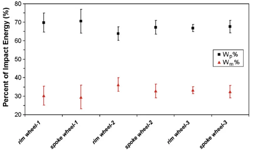
- Figure 8: Indicates that crack propagation energy (Wp) constitutes a significant portion (60-75%) of the total impact energy. As-cast wheel-1 shows the highest percentage of Wp, despite having the lowest overall impact energy.
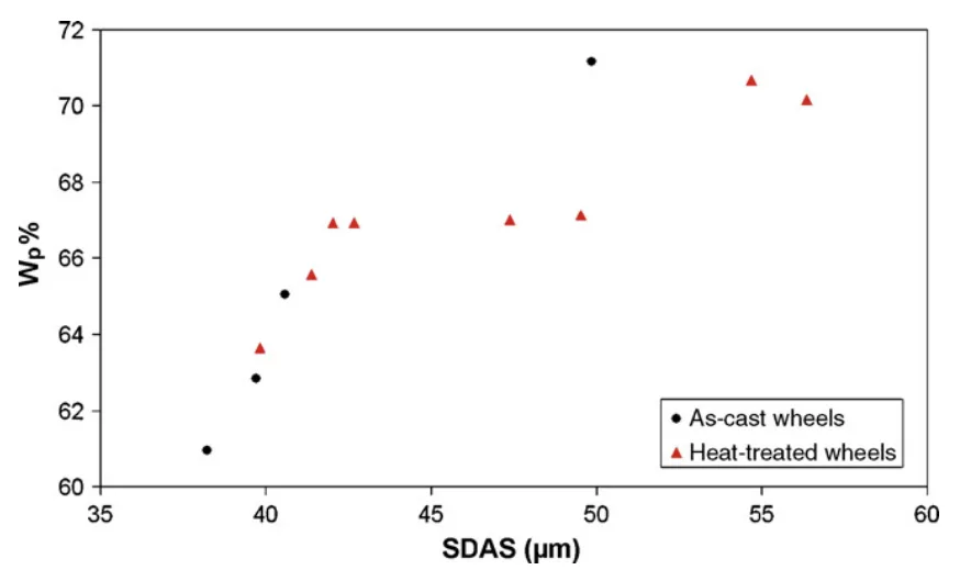
- Figure 9: Demonstrates a negative correlation between SDAS and Wp%, suggesting that finer microstructures (lower SDAS) tend to have a lower percentage of energy absorbed in crack propagation, possibly due to increased crack initiation resistance in finer structures.
- Table 2: Quantifies the inverse relationship between SDAS and impact energy. Lower SDAS values (finer microstructure) are associated with higher impact energy, particularly evident when comparing rim vs. spoke regions and as-cast vs. T6 conditions.
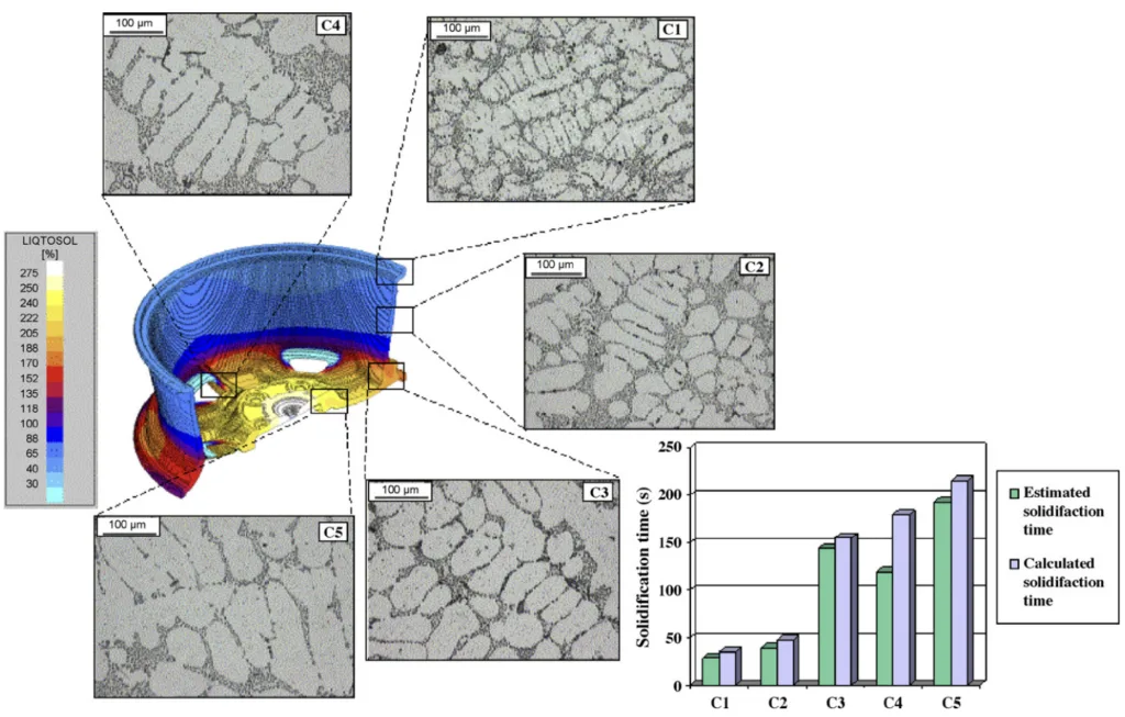
- Figure 17: Shows a reasonable agreement between calculated and estimated (SDAS-based) solidification times, validating the numerical simulation's ability to predict solidification behaviour.
Figure Name List:
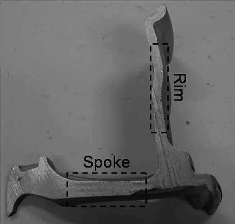
- Fig. 1 - Position of the spoke and the rim zone in the wheels analysed.
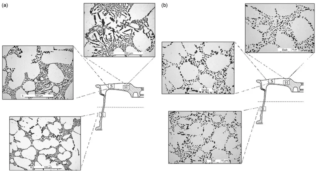
- Fig. 2- Microstructure of (a) wheel-1 and (b) wheel-2 with reference to the different positions analysed.
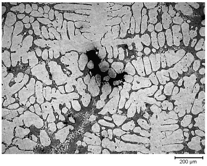
- Fig. 3 - Optical micrograph of a shrinkage porosity in the rim zone.
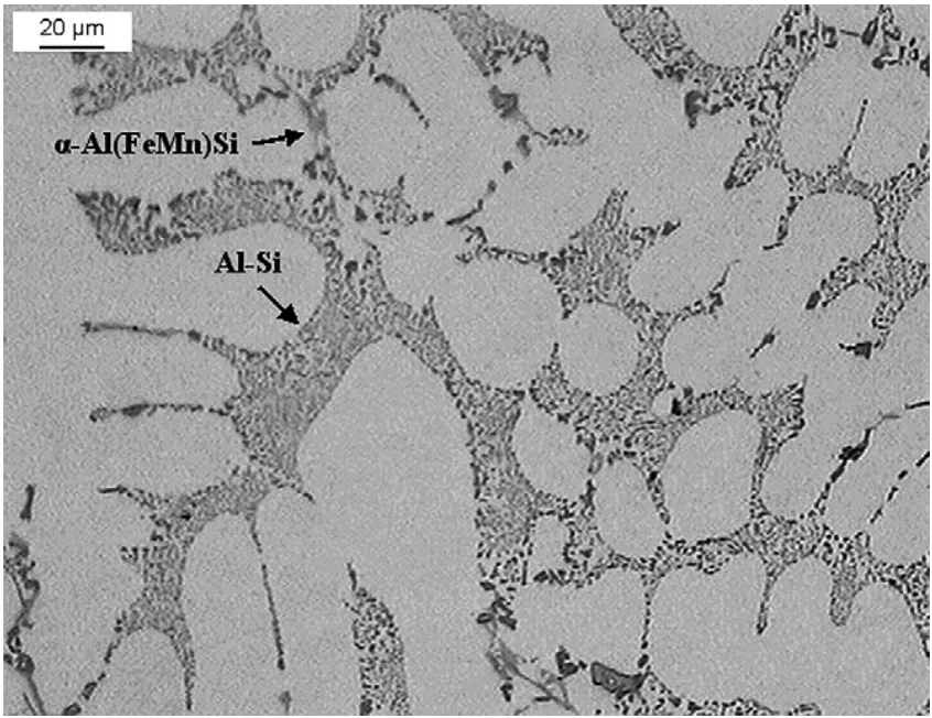
- Fig. 4- Optical micrograph showing secondary phase particles in rim area of wheel-1. The eutectic silicon is in the form of fibrous particles in the interdendritic channels.
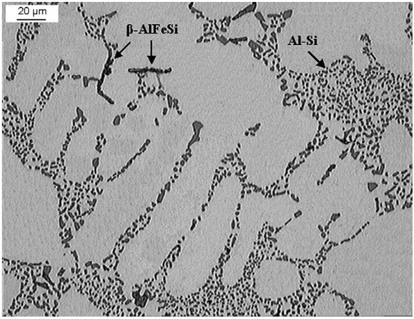
- Fig. 5 Optical micrograph showing secondary phase particles in rim area of wheel-3. The distribution of eutectic silicon is homogeneous and globular.
- Fig. 6 - Impact energy and maximum load measured in the different positions of the wheels. The standard deviations are shown as error bars.
- Fig. 7 - Load-time curves of samples obtained from spoke and rim area of (a) wheel-1 and (b) wheel-3.
- Fig. 8 - Percentage of energy absorbed during crack nucleation and propagation and measured at different positions of the wheels analysed. The standard deviations are shown as error bars.
- Fig. 9 - Correlation between SDAS and Wp% (percentage of energy absorbed during crack propagation).
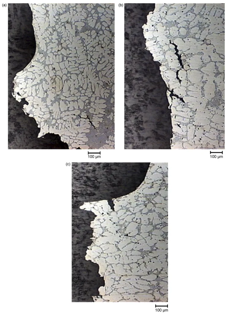
- Fig. 10 Optical micrographs of the fracture profiles of samples drawn from (a) the rim of wheel-1 and from (b) the spoke of wheel-2 and (c) wheel-3. Secondary cracks are evident.
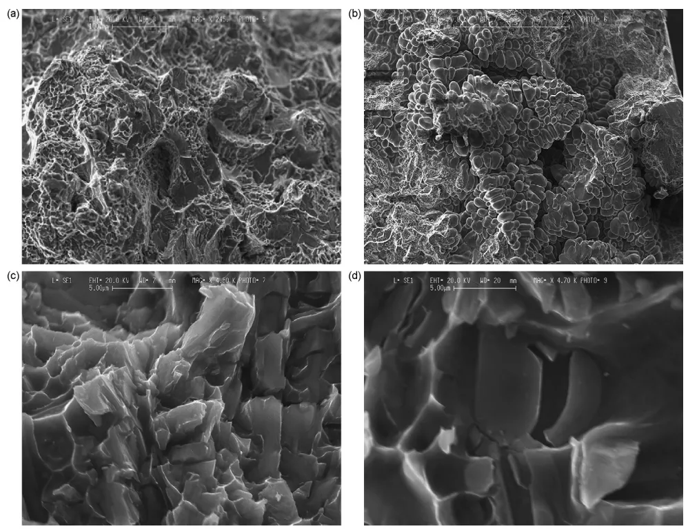
- Fig. 11 - Features of the fracture surfaces of the Charpy specimens drawn from the wheels analysed as revealed by SEM. (a) Transcrystalline and ductile fracture from the spoke of wheel-2; (b) interdendritic fracture from the rim of wheel-1; (c) micronecks and dimples from the rim of wheel-1; (d) cleavage fracture in the silicon precipitate from the rim of wheel-3.
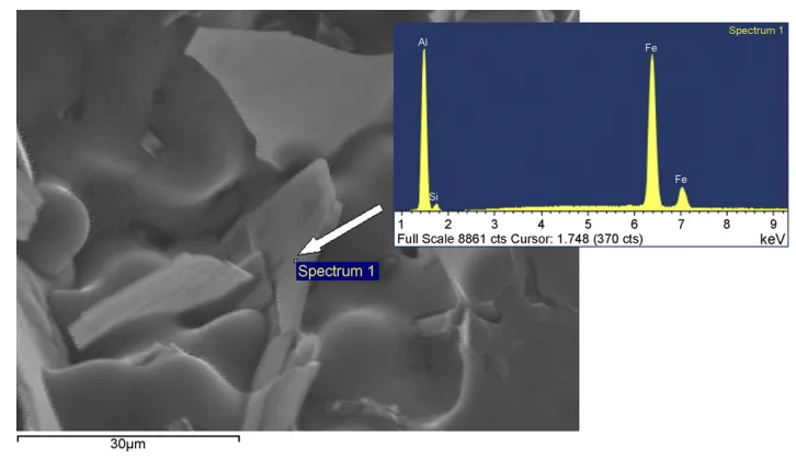
- Fig. 12 - SEM micrograph of β-AlFeSi platelet, on the fracture surface of sample drawn from the spoke of wheel-3, with EDS spectra.
- Fig. 13 - Percentage porosity measured at different positions of the wheels analysed. The standard deviations are shown as error bars.
- Fig. 14 - Micro-focus X-ray image of Charpy sample showing the presence of porosity around the notch.
- Fig. 15 - Impact energy of some samples drawn from the spoke of wheel-3 associated with respective X-ray images, taken in the zone around the V-notch. The X-ray images refer to a high-defect (a), medium-defect (b) and low-defect (c) content.
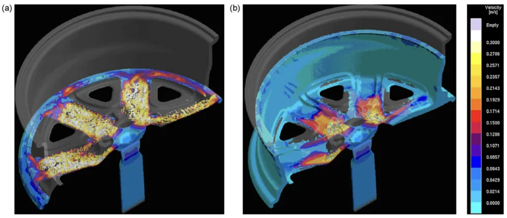
- Fig. 16 - Calculated melt velocity at (a) 20% and (b) 70% of die filling of wheel-1.
- Fig. 17 - Calculated solidification times with corresponding microstructure within wheel-2. Solidification times, estimated by means of SDAS measurements and calculated with a numerical simulation approach, were compared.
- Fig. 18 - Shrinkage porosity in the rim area and in the junction between the spoke and the rim within wheel-2. These zones are critical for feeding. The casting shrinkage is indicated by a feeding criterion.
7. Conclusion:
Summary of Key Findings:
This study investigated the impact behaviour of LPDC A356 aluminium alloy automotive wheels. Key findings include: T6 heat treatment significantly improves impact properties; finer microstructure enhances impact strength; casting defects, especially porosity near stress concentration points, are detrimental; crack propagation occurs along interdendritic eutectic regions; and numerical simulation effectively predicts solidification and defect formation.
Academic Significance of the Study:
This research contributes to a deeper understanding of the relationship between processing parameters (LPDC, heat treatment), microstructure (SDAS, eutectic silicon), casting defects (porosity), and impact properties of A356 aluminium alloy wheels. It highlights the importance of microstructure control and defect minimization in achieving desired mechanical performance in die-cast components. The study also validates the use of numerical simulation as a predictive tool in die casting process design and optimization.
Practical Implications:
The findings provide practical guidelines for optimizing the LPDC process and heat treatment for manufacturing high-performance aluminium alloy wheels. Minimizing porosity, particularly in critical stress areas, and achieving a finer microstructure through process control are crucial for enhancing impact resistance. Numerical simulation can be used as a valuable tool for process design, defect prediction, and quality control in wheel manufacturing.
Limitations of the Study and Areas for Future Research:
The study is limited to A356 alloy and specific wheel designs. Further research could explore:
- Impact behaviour of other aluminium alloys and wheel designs.
- Effect of different T6 heat treatment parameters on impact properties.
- Detailed analysis of the influence of specific types and distributions of casting defects.
- Correlation of fatigue performance with microstructure and casting defects in LPDC wheels.
- Application of advanced numerical simulation techniques for more accurate defect prediction and process optimization.
8. References:
- Berto, F., Lazzarin, P., Wang, C.H., 2004. Three-dimensional linear elastic distributions of stress and strain energy density ahead of V-shaped notches in plates of arbitrary thickness. Int. J. Fract. 127, 265-282.
- Blackmun, E.V., 1968. Casting. In: Kent, R., Van Horn (Eds.), Aluminum Vol. III—Fabrication and Finishing, 3rd ed. American Society for Metals, Metals Park, OH, pp. 43–80.
- Bonollo, F., Gramegna, N., Odorizzi, S., 1999. La pressocolata delle leghe di alluminio: simulazione numerica del processo, 1st ed. Edimet, Brescia.
- Brown, R., 1999. Foseco Non-Ferrous Foundryman's Handbook, 11th ed. Butterworth-Heinemann, Oxford.
- Cáceres, C.H., Davidson, C.J., Griffiths, J.R., 1995. The deformation and fracture behaviour of an Al-Si-Mg casting alloy. Mater. Sci. Eng. A 197, 171–179.
- Cáceres, C.H., Selling, B.I., 1996. Casting defects and the tensile properties of an Al-Si-Mg alloy. Mater. Sci. Eng. A 220, 109-116.
- Campbell, J., 2003. Castings, 2nd ed. Elsevier/Butterworth-Heinemann, Oxford.
- Flinn, R.A., 1963. Fundamentals of Metal Casting, 1st ed. Addison-Wesley Publishing Company, Massachusetts.
- Kuo, J.-H., Hsu, F.-L., Hwang, W.-S., 2001. Development of an interactive simulation system for the determination of the pressure-time relationship during the filling in a low pressure casting process. Sci. Technol. Adv. Mater. 2, 131-145.
- Kurz, W., Fisher, D.J., 1998. Fundamentals of Solidification, 4th ed. Trans. Tech. Publications, Switzerland.
- Li, Z., Samuel, A.M., Samuel, F.H., Ravindran, C., Doty, H.W., Valtierra, S., 2004. Parameters controlling the performance of AA319-type alloys. Part II. Impact properties and fractography. Mater. Sci. Eng. A 367, 111-122.
- MAGMASOFT® v.4.2, 2002. MAGMAlpdc Module Manual, MAGMA Giessereitechnologie GmbH.
- Murali, S., Raman, K.S., Murthy, K.S.S., 1992. Effect of magnesium, iron (impurity) and solidification rates on the fracture toughness of Al-7Si-0.3Mg casting alloy. Mater. Sci. Eng. A 151, 1-10.
- Paray, F., Kulunk, B., Gruzleski, J.E., 2000. Impact properties of Al-Si foundry alloys. Int. J. Cast Met. Res. 13, 17-37.
- Pedersen, L., 1999. Solution Heat Treatment of AlSiMg Foundry Alloys. PhD Thesis. Norwegian University of Science and Technology (NTNU), Trondheim.
- Schroth, A., Schemme, D., 2003. Simulation in modern quality management systems-simulation assists the implementation of quality management systems in foundries. Cast. Plant Technol. 19, 8-18.
- Shivkumar, S., Wang, L., Keller, C., 1994. Impact properties of A356-T6 alloys. J. Mater. Eng. Perform. 3, 83-90.
- Sicha, W.E., 1971. Properties of commercial casting alloys. In: Kent, R., Van Horn (Eds.), Aluminum Vol. I-Properties, Physical Metallurgy and Phase Diagram, 4th ed. American Society for Metals, Metals Park, OH, pp. 277-302.
- Srivastava, M.C., Lohne, O., Arnberg, L., Laukli, H.I., Gjestland, H., 2006. Energy absorption of HPDC aluminium and magnesium alloys. In: Proc. High Tech Die Casting 2006, Vicenza, Italy, paper 10.
- Street, A.C., 1986. The Diecasting Book, 2nd ed. Portcullis Press, London.
- Vedani, M., Mapelli, C., 2001. Effect of thermal treatments on microstructure and impact toughness of die-cast Mg-Al-Mn alloys. Mater. Sci. Technol. 17, 938-944.
- Wang, Q.G., Cáceres, C.H., 1998. The fracture mode in Al-Si-Mg casting alloys. Mater. Sci. Eng. A 241, 72-82.
- Warmuzek, M., 2004. Aluminium-Silicon Casting Alloys: Atlas of Microfractographs, 1st ed. ASM International.
- Zhang, D.L., Zheng, L.H., StJohn, D.H., 2002. Effect of a short solution treatment time on microstructure and mechanical properties of modified Al-7 wt.% Si-0.3 wt.% Mg alloy. J. Light Met. 2, 27-36.
9. Copyright:
- This material is "Mattia Merlin, Giulio Timelli, Franco Bonollo, Gian Luca Garagnani"'s paper: Based on "Impact behaviour of A356 alloy for low-pressure die casting automotive wheels".
- Paper Source: https://www.researchgate.net/publication/222707551
This material was summarized based on the above paper, and unauthorized use for commercial purposes is prohibited.
Copyright © 2025 CASTMAN. All rights reserved.