This article introduces the paper "A new hybrid method for demoldability analysis of discrete geometries" presented in Computer-Aided Design.
1. Overview:
- Title: A new hybrid method for demoldability analysis of discrete geometries
- Author: Jorge Manuel Mercado-Colmenero, M. A. R. Paramio, Jesus Maria Perez-Garcia, Cristina Martin-Doñate
- Publication Year: 2022 (Based on journal information, copyright notice in document is 2025)
- Publishing Journal/Academic Society: Computer-Aided Design
- Keywords: Demoldability analysis, geometric analysis, injection molding, computer aided manufacturing
2. Research Background:
- Social/Academic Context of the Research Topic: Injection molding is a widely used manufacturing process for plastic parts with complex geometries and freeform surfaces. Demoldability analysis is crucial in mold design to ensure part quality and reduce manufacturing costs. Validating demoldability quickly and accurately, especially during the conceptual design phase, is essential for efficient product development and cost estimation.
- Limitations of Existing Research: Current commercial CAD systems for demoldability analysis often require significant manual interaction from designers. Existing research methods may be linked to specific modelers, require additional hardware like GPUs, or are not applicable to all types of plastic parts. These methods may also lack accuracy compared to feature-recognition based approaches.
- Necessity of the Research: There is a need for a more automated, efficient, and universally applicable method for demoldability analysis in injection molding. This is driven by the need to reduce design and manufacturing time, improve part quality, and enable rapid design changes in the industry.
3. Research Purpose and Research Questions:
- Research Purpose: To present a new method for automatic demoldability analysis of plastic parts manufactured by injection molding. The method is based on the discrete model of the plastic part, using a triangular mesh, and performs a hybrid analysis of both mesh nodes and facets.
- Key Research Questions: The paper aims to address the limitations of existing methods by developing an algorithm that:
- Is valid for all kinds of plastic parts.
- Is independent of the CAD modeler used.
- Does not require additional hardware.
- Detects both lateral undercuts resolvable by side cores and non-demoldable areas.
- Research Hypotheses: The proposed hybrid method, analyzing both mesh nodes and facets, will provide a more comprehensive and accurate demoldability analysis compared to existing methods, improving upon limitations related to applicability, automation, and hardware requirements.
4. Research Methodology:
- Research Design: Development of a new hybrid algorithm for demoldability analysis based on a discrete mesh model. The algorithm involves preprocessing, facet cataloging, reclassification of semi-demoldable facets, and parting line definition.
- Data Collection Method: The algorithm was tested on five industrial parts manufactured by injection molding and two real parts to validate its performance.
- Analysis Method: The algorithm was implemented in C++. The performance was evaluated by analyzing simulation time and comparing results across different part geometries. The computational cost of the algorithm was also assessed.
- Research Subjects and Scope: The research focuses on the geometric demoldability analysis of plastic parts represented by triangular mesh models for injection molding processes. The algorithm analyzes demoldability with respect to a given parting direction.
5. Main Research Results:
- Key Research Results: The proposed algorithm successfully performs demoldability analysis by classifying mesh facets into demoldable, non-demoldable, and semi-demoldable categories. It generates a new virtual discrete geometry that incorporates manufacturing information, providing a demoldability map of the plastic part. The algorithm detects lateral undercuts and non-demoldable areas.
- Statistical/Qualitative Analysis Results: The paper presents simulation times for different parts (Cases A-G') in Table 1 and Table 2, and graphically in Fig. 22. For example, for Part A (306 facets), the simulation time was 30.282 seconds. A linear relationship between the number of facets and the computation time was observed, with a ratio of time/number of facets being approximately 0.85.
- Data Interpretation: The results demonstrate the effectiveness of the hybrid method in analyzing demoldability for various part geometries. The algorithm is computationally efficient, as indicated by the linear relationship between facet count and processing time. The Inproject algorithm, a sub-algorithm of the method, was found to be significantly faster than the Isoobstructing algorithm, taking only 6% of its computation time.
- Figure Name List:
- Fig.1a.- Converting a CAD model to a virtual faceted model.
- Fig.1b.- Definition of facets and nodes, triangular shell elements.
- Fig 2- Defining the set of nodes / facets belonging to Plk.
- Fig 3- Representation of facets Fi for the level k of Ik, definition of Ck
- Fig 4.- Projection of facets Fi and contour border Fr(Ck) for the level k of Ik .
- Fig5.- Partial demoldability analysis for a plane (Plk)
- Fig6.- Result of the algorithm InProject in the analysis (+V₂).
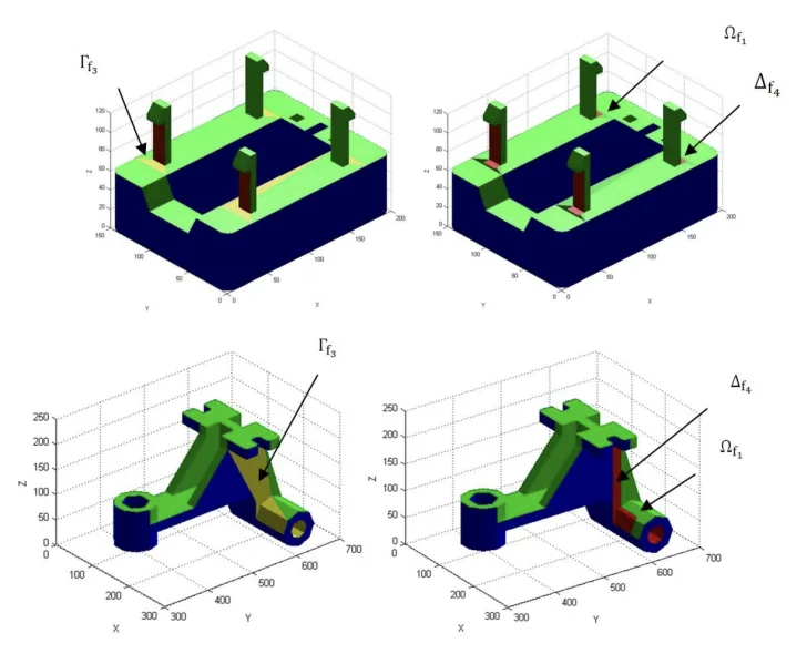
- Fig7.- Example of location of the region Of₁
- Fig8.- Example of location of the region [If U Af₄].
- Fig 9.- Example location of demoldable facets, perpendicular to V2.
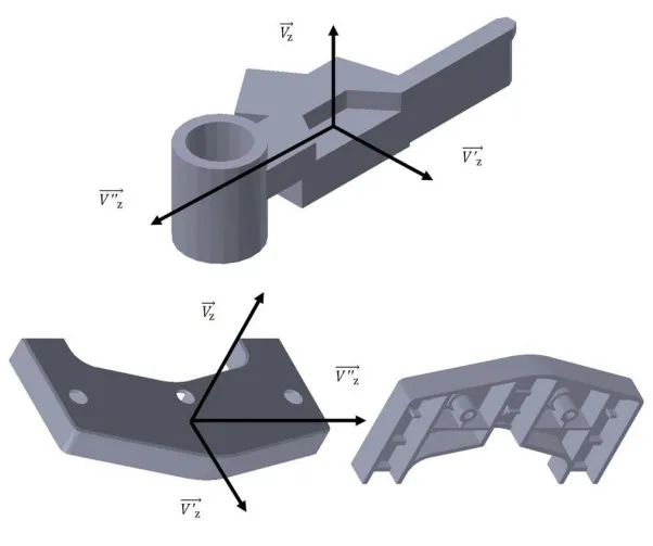
- Fig 10.- Reorientation of the geometry as the new direction of analysis, and comparison of results of different analyses performed.
- Fig 11.- Results of the analysis of demoldability in +Vz, -Vz after the implementation of the boundary conditions 3.3.2
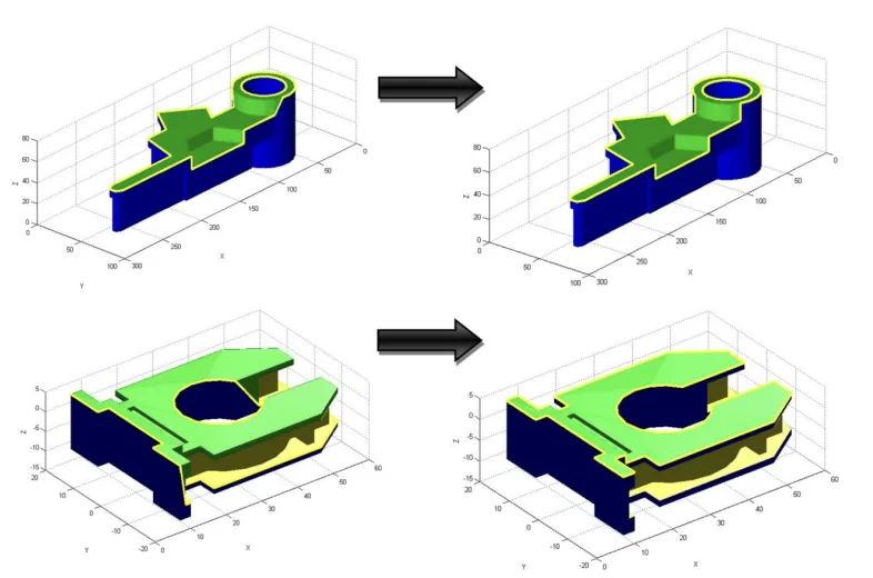
- Fig12.- Example of resolution of semi-demoldable facets, Boolean operation (intersection and subtraction).
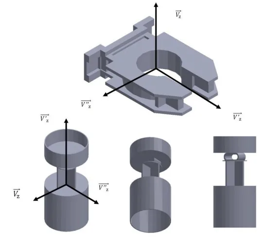
- Fig 13a.- Allocation of non-demoldable facets to side core facets, Example I.
- Fig13b.- Allocation of non-demoldable facets to side core facets, Example II.
- Fig 14.- Geometric definition of the parting line.
- Fig 15.- Optimizing the geometrical definition of the parting line.
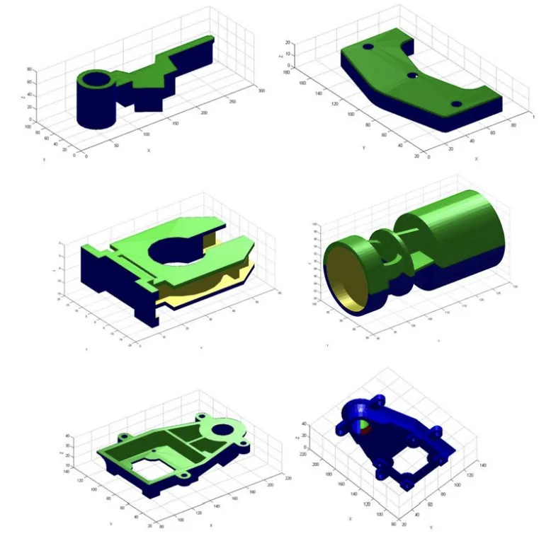
- Fig 16.- Case A and B, demoldable parts by means of upper and lower cavities.
- Fig 17.- Parts C, D with resoluble demolding regions by means of side cores.
- Fig18.- Part E, parts with non-demoldable regions.
- Fig 19.- Cases F and G. Parts with non demoldable regions, geometrically modified to improve their demoldability.
- Fig20.- Results of demoldability, Cases A, B, C, D, E.
- Fig21.- Results of demoldability, Cases F, G original part and Cases F',G' optimized part..
- Fig22.- CPU Computational Cost of Demoldability Algorithm.
- Fig23.- Formal definition of Gauss points of a facet.
Parts F and G have been used as an example of optimizing the geometry of the part as a methodology in order to enhance its demoldability, Table 2 shows the results of applying the demoldability analysis algorithm over both parts.
6. Conclusion and Discussion:
- Summary of Main Results: The paper concludes that the proposed hybrid method effectively analyzes demoldability by combining node and facet analysis on a discrete mesh. The algorithm is validated on industrial parts, demonstrating its ability to identify demoldable, non-demoldable, and side-core resolvable areas.
- Academic Significance of the Research: The research contributes a novel approach to demoldability analysis by using a hybrid discrete method, offering an alternative to existing techniques that may be limited by modeler dependency or computational demands. The method's efficiency, particularly the Inproject sub-algorithm, is highlighted.
- Practical Implications: The developed algorithm provides a valuable tool for designers in the injection molding industry. It enables automated demoldability checks early in the design process, facilitating design modifications to improve manufacturability and reduce production costs. The algorithm's CAD modeler independence and low hardware requirements enhance its practical applicability.
- Limitations of the Research: The paper acknowledges that while the method is valid for any geometry, further research could explore performance across a wider range of plastic materials and molding conditions.
7. Future Follow-up Research:
- Directions for Follow-up Research: Future work could focus on:
- Integrating the algorithm into commercial CAD/CAE systems.
- Extending the algorithm to consider different plastic materials and molding parameters.
- Further optimization of the algorithm's computational efficiency, potentially through GPU acceleration.
- Exploring the application of the algorithm in conjunction with other mold design stages, such as cooling and ejection system design.
- Areas Requiring Further Exploration: Improving the accuracy of demoldability analysis for complex and micro-featured parts and developing automated mold design systems based on demoldability analysis results are suggested areas for future exploration.
8. References:
- [1] Chen L.L., Woo T.C. Computational geometry on the sphere with application to automated machining. ASME Transactions. Journal of Mechanical Design 114, 288-295.
- [2] Chen L.L., Chou S.Y, Woo T.C. Parting directions for mould and die design. Computer Aided Design 1993;25 (12): 762-8.
- [3] Chen L.L., Chou S.Y, Woo T.C. Partial visibility for selecting a parting direction in mold and die design. Journal of Manufacturing Systems 1995; 14 (5):.
- [4] Weinstein M, Manoochehri S. Optimal parting direction of molded and cast parts for manufacturability. Journal of Manufacturing Systems 1997; 16(1):1-12.
- [5] Fu M.W, Fuh J.Y.H., Nee A.Y.C. Undercut feature recognition in an injection mould design system. Computer Aided Design 1999; 31(12):777-790.
- [6] Fu M.W., Fuh J,Y.H., Nee A.Y.C. Generation of optimal parting direction based on undercut features in injection molded parts. IIE Transactions 1999; 31: 947-55.
- [7] Fu M.W, Nee A.Y.C., Fuh J.Y.H. The application of surface visibility and moldability to parting line generation. Computer Aided Design 2002; 34(6): 469-480.
- [8] Fu M.W., Nee A.Y.C., Fuh J.Y.H. A core and cavity generation method in injection mold design. International Journal of Production Research 2001; 39:121-38.
- [9] Fu M.W., The application of surface demoldability and moldability to side core design in die and mold CAD. Computer Aided Design 2008; 40(5): 567-575.
- [10] Ran JQ, Fu MW. Design of internal pins in injection mold CAD via the automatic recognition of undercut features. Computer Aided Design . 2010;42(7):582-597.
- [11] Wuerger D, Gadh R. Virtual prototyping of die design part one: theory and formulation. J Concurrent Engng: Res Appl 1997; 5(4):307–15.
- [12] Wuerger D, Gadh R. Virtual prototyping of die design part two: algorithmic, computational, and practical considerations. J Concurrent Engng: Res Appl 1997; 5(4):317–26.
- [13] Kurth GR, Gath R. Virtual prototyping of die-design: determination of die-open directions for neat-net shape manufactured parts with extruded or rotational features. Computer Integrated Manufacturing Systems 1997; 10(1):69- 81.
- [14] Lu HY, Lee WB. Detection of interference elements and release directions in die-cast and injection-moulded components. Proceedings of the Institution of Mechanical Engineers, Part B Journal of Engineering Manufacture 2000; 214(6):431–41.
- [15] Yin ZP, Han Ding, You-Lun Xiong: Virtual prototyping of mold design: geometric mouldability analysis for near-net-shape manufactured parts by feature recognition and geometric reasoning. Computer-Aided Design 2001: 33(2): 137-154
- [16] Ye X.G. Fuh JYH, Lee K.S.: A hybrid method for recognition of undercut features from molded part. ComputerAided Design 2001; 33(14):1023-34.
- [17] Ye X.G. Fuh JYH, Lee K.S.: Automotive undercut feature recognition for side core design of injection molds. Journal of Mechanical Design 2004; 126:519-26.
- [18] Zhang Chunjie, Zhou Xionghui, Li Congxin. Feature extraction from freeform molded parts for moldability analysis. International Journal of Advanced Manufacturing Technology. 2010;48(1-4):273-82.
- [19] Bassi R., Reddy NV, Bedi S.Automatic recognition of intersecting features of side core design in two piece permanent molds. International Journal of Advanced Manufacturing Technology. 2010;50(5-8):421-39.
- [20] Surti A., Reddy NV. Non discretized approach to visibility analysis for automatic mold feature recognition using step part model. Journal of Advanced Manufacturing Systems. 2012;11(1): 1-16.
- [21] Singh R, Madan J, Kumar R. Automated identification of complex undercut features for side core design for die casting parts. Journal of Engineering Manufacture. 2014;228(9):1138-1152.
- [22] Nee A.Y.C., Fu, M.W., Fuh J.Y.H., Lee K.S., Zhang Y.F. Determination of optimal parting direction in plastic injection mould design. Annals of the CIRP.1997:,46(1): 429-432.
- [23] Nee A.Y.C., Fu M.W., Fuh J.Y.H, Lee K.S., Zhang Y.F. Automatic determination of 3D parting Lines and Surfaces in Plastic Injection Mould Design. Annals of the CIRP. 1998: 47(1): 95-99.
- [24] Hui K.C., Tan S.T. Mould design with sweep operations, a heuristic search approach.Computer Aided Design . 1992; 24 (2): 81-92.
- [25] Ravi B., Srinivasan M.N. Decision criteria for computer aided parting surface design-Computer Aided Design.1990; 22(1):11-18.
- [26] Rappaport D, Rosenbloom A. Moldable and castable polygons. Comput Geom: Theory Appl 1994;4:219–33.
- [27] Ahn, H.K., Berg, M.T. de, Bose, J., Cheng, S.W., Halperin, D. & Matouvsek, J. Separating an object from its cast. In Proceedings 13th Annual ACM Symposium on Computational Geometry 1997; 61-83. New York, U.S.A.: ACM Press.
- [28] Ahn, De Berg, Bose, Cheng ,Halperin , Matousek , Swartzkopf, Separating an object from its cast. Computer Aided Design. 2002;34: 547-59,.
- [29] Chen X, McMains S. Finding all undercut-free parting directions for extrusions. In: Geometric modeling and processing. Lecture notes in computer science, 2006; 4077: 514–27.
- [30] Mcmains S, Chen X. Determining moldability and parting directions for polygons with curved edges.In: International mechanical engineering congress and exposition. ASME Anaheim , CA; 2004.
- [31] Mcmains S, Chen X. finding undercut free directions for polygons with curved edges. ASME Journal of Computing and Information Science in Engineering.2006; 6(1):60-68.
- [32] Yin ZP, Han Ding, Han-Xiong Li, You-Lun Xiong: Geometric mouldability analysis by geometric reasoning and fuzzy decision making. Computer Aided Design. 2004; 36(1): 37-50.
- [33] Chen YH, Wang YZ, Leung TM. An investigation of parting direction based on dexel and fuzzy decision making. International Journal of Production Research.2000;38:1357–75.
- [34] Huang J, Gupta SK, Stoppel K. Generating sacrificial multi-piece molds using accessibility driven spatial partitioning. Computer Aided Design 2003;35(3):1147–60.
- [35] Dhaliwal S, Gupta SK, Huang J, Computing exact global accessibility cones for polyhedral objects. In ASME Design for Manufacturing Conference Baltimore MD, September 2000.
- [36] Dhaliwal S, Gupta SK, Huang J, Priyadarshi A. Algorithms for computing global accessibility cones. Journal of Computing and Information Science in Engineering 2003;3(3):200–9.
- [37] Priyadarshi A.K.L., Gupta S.K. Geometric Algorithms for automated design of multipiece permanent molds. Computer Aided Design 2004; 36(3): 241-260.
- [38] Bourne D, Corney J, Gupta S.K. Recent advances and future challenges in automated manufacturing planning. Journal of Computing and Information Science in Engineering 2011; 11(2).
- [39] Chen Y, Rosen D. A region based approach to automated design of multipiece molds with application to rapid tooling .In ASME Design Engineering Technical conference, Pittsburgh PA, 2001;613-623.
- [40] Chen Y, Rosen DW. A reverse glue approach to automated construction of multi-piece molds. J. Comput Inf Sci Eng 2003;3(3):219–30.
- [41] Ganter M.A., Tuss L.L. Computer-Assisted Parting Line Development for Cast Pattern Production. AFS Transactions 1990; 795-800 .
- [42] Wong T., Tan S.T., Sze W.S. Parting line formation by slicing a trimmed surface model.Proceedings of the 1996 ASME Design Engineering Technical Conference and Computers in Engineering Conference 1996.August 18-22, Irvine, California.
- [43] Rubio M.A.,Pérez J.M., Rios J. A Procedure for plastic parts demoldability analysis Robotics and Computer Integrated Manufacturing 2006; 22(1):81-92.
- [44] Martin Doñate C, Rubio Paramio, M. A. New methodology for demoldability analysis based on volume discretization algorithms. Computer Aided Design.2013; 45(2): 229-240.
- [45] Martin Donate Cristina, Rubio Paramio Miguel Angel, Mesa Villar Aurelio. Método de validación automatizada de la fabricabilidad de diseños de objetos tridimensionales en base a su geometría. Patent number: ES2512940
- [46] Khardekar R, McMains S. Finding mold removal directions using graphics hardware. In: ACM workshop on general purpose computing on graphics processors; 2004, pp. C-19, (abstract).
- [47] Khardekar, Burton and McMains. Finding feasible mold parting directions using graphics hardware. Computer Aided Design 2006; 38(4):327-41.
- [48] Chakraborty P., Reddy NV. Automatic determination of parting directions, parting lines and parting surfaces for two piece permanent moulds. Journal of Materials Processing Technology 2000;209(5):2464-76.
- [49] Singh R, Madan J. Systematic approach for automated determination of parting line for die-cast parts. Robotics and Computer-Integrated Manufacturing. 2013;29(5):346-366.
- [50] Shin K.H. Lee K.W. Design of side cores of injection molds from automatic detection of interference faces. Journal of Design and Manufacturing 1993;3:225-36
- [51] Banerjee A.G., Gupta S.K.Geometrical algorithms for automated design of side actions in injection moulding of complex parts. Computer Aided Design. 2007;39(10): 882-897.
- [52]Li W, Martin RR, Langbein FC. Molds for meshes: Computing smooth parting lines and undercut removal. IEEE Transactions on Automation Science and Engineering 2009; 6(3):423-32.
9. Copyright:
- This material is Jorge Manuel Mercado-Colmenero et al.'s paper: Based on A new hybrid method for demoldability analysis of discrete geometries.
- Paper Source: [DOI URL: https://doi.org/10.1016/j.cad.2022.103432]
This material was summarized based on the above paper, and unauthorized use for commercial purposes is prohibited.
Copyright © 2025 CASTMAN. All rights reserved.