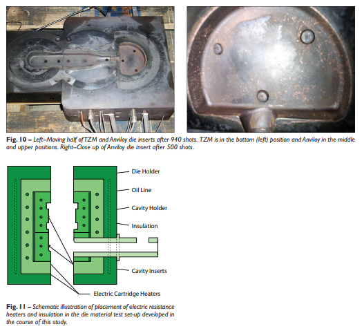
Fig. 10 – Left–Moving half of TZM and Anviloy die inserts after 940 shots. TZM is in the bottom (left) position and Anviloy in the middle and upper positions. Right–Close up of Anviloy die insert after 500 shots. Fig. 11 – Schematic illustration of placement of electric resistance heaters and insulation in the die material test set-up developed in the course of this study
Fig. 10 – Left--Moving half of TZM and Anviloy die inserts after 940 shots. TZM is in the bottom (left) position and Anviloy in the middle and upper positions. Right--Close up of Anviloy die insert after 500 shots. Fig. 11 – Schematic illustration of placement of electric resistance heaters and insulation in the die material test set-up developed in the course of this study