S. Cecchel, D. Ferrario
The purpose of the present paper is to enhance and deepen the lightweight optimization in automotive, in particular for commercial vehicles and buses. In detail, aim of this research is to develop a technically reliable and cost effective safety component for Light Commercial Vehicles (LCVs) in aluminum alloy. At this purpose, different solutions of Aluminium Cross beams for an independent front suspension for LCVs have been analyzed, with a weight saving target in comparison with the traditional welded sheet metal structure of almost 40/50%. Moreover, further environmental advantages have to be considered; for instance improved corrosion resistance, no painting or cataphoresis required, benefits on recyclability and residual value at the end of life. In detail, the goal of this project has been achieved through: technical and economical study of some different lightweighting solution and selection of the best case; improvement of the solution selected with the help of structural FEA and casting process simulations, a Life Cycle Assessment from cradle to grave (not here described), prototypes realization and preliminary experimental correlation.
Keywords
Aluminum - high pressure die casting - suspension - cross beam - commercial vehicle -
lightweight - automotive
INTRODUCTION
Vehicle weight decrease is a remarkable method to moderate the automotive carbon footprint, by reducing fuel consumptions and environmental emissions. Furthermore, the lightweighting improves power to weight ratio and passenger safety and allows an increase of the payload [1]. For these reasons, in the last years the lightweighting design in automotive has exponentially increased. Although, the use of “steel” and “iron” is still predominant for commercial vehicles and buses especially for safety relevant components [2]. Aim of this research is to overcome this state of the art by developing a technically reliable and cost effective safety relevant suspension component for Light Commercial Vehicles (LCVs) in aluminum alloy. With the purpose to evaluate the element that gives the higher lightweighting benefit a preliminary benchmark on a complete suspension assembly has been performed, outlining the object of the study in a suspension cross beam element.
In particular, the function of a suspension cross beam is to guarantee the connection with the frame and to support all the suspension elements (i.e. control arms, bumpers, springs, etc.), steering systems and driveline components, connecting all the kinematic theoretical suspension “hard points”. In order to ensure the fulfillment of these important functions, these components have to resist to the mission loads (fatigue, overloads, impulsive single events, etc.), to guarantee high stiffness for good vehicle handling, to reduce road vibrations, to support potential overloads (standard, payload, acceleration, etc.) frequent in LCVs and to correctly distribute the consequent stress along the chassis frame.
Therefore, a suspension cross beam for commercial vehicles is usually made with metal sheet parts or steel tubes welded together and protected to avoid corrosion. In order to meet the lightweighting requirements, the main technological trends are looking to alternative materials such as Advanced High Strength Steel, light alloys or composites, depending on the specific automotive sectors. For instance, even if light alloys and composites would offer the best weight benefit, the use of these technologies in LCVs is limited both for the necessity of high er stress at break and stiffness, both for cost limits. In particular, at the current known state of the art none suspension cross beam in aluminum has never developed in this range of vehicles.
With the purpose to overcome these limits, during the present work the shape and the production technology of the studied component have been completely devised by optimizing the mechanical properties and by reducing the material used. The final structure will be comparable or better than the traditional system in terms of mechanical resistance and stiffness.
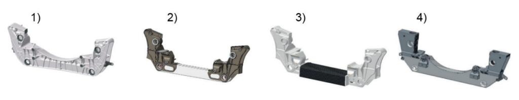
After these analyses, case study 3 and case study 4 have been discarded respectively for economical reasons and for technicaleconomical feasibility.
Therefore, case study 1 and case study 2 components’ design have been enhanced thanks to further iterations of structural and process finite element analyses. In detail, an elastokinematic multibody model of the suspension system has been defined and performed in MSC/AdamsCar in order to determine the forces of the main load set conditions.
These loads have been used as inputs for the structural FEA performed in MSC Marc/Mentat and the results compared with the outputs of the ESI/PROCAST process FEA. Finally, the comparison of the different analyses’ results has led to the conclusion that the solution with the most lightweight and economic potential was high pressure die casting aluminum. The feasibility of this solution has been achieved by the use of proper materials and by a new concept of design that allowed to overcome the structural limits explained in the introduction.
The alloy selected for the production has been AlSi9MgMn (Tab. 1), that guarantees as-cast elevated mechanical properties (Tab.1). Indeed, this is a matter of great importance because a high temperature heat treatment (i.e. T6) may cause considerable deformations and blisters. Anyway, an additional lower temperature T5 heat treatment has been evaluated in order to slightly increase the resistance for heavy applications (Tab.1).
![Tab. 1 - Chemical composition AlSi9MgMn (left) [5], Mechanical properties AlSi9MgMn (right)[5]](https://castman.co.kr/wp-content/uploads/Tab.-1-Chemical-composition-AlSi9MgMn-left-5-Mechanical-properties-AlSi9MgMn-right5.png)
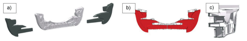
Furthermore, the high corrosion resistance of this low-iron and copper aluminum alloy allowed to remove cataphoresis and painting treatments requested in the previous steel production with consequently economical, environmental and quality benefits. Indeed, not only materials determine mechanical properties of components but also design. In this context, the main innovation was the substitution of the traditional high pressure die casting plane or “U” shape with a completely hollow structure obtained through the addition of sliders for the total length of the component (Fig. 2).
As is well known, sliders are a technology widely used to avoid undercuts but are not applied for the manufacturing of hollow structural components, especially in the field of LCVs. With the same purpose, some alternative methods (i.e. salt cores, ceramic cores, gas injection process, etc.) [3],[4] have been recently developed but needs further efforts to achieve a sustainable industrialization (i.e. decoring problems). In conclusion, the high mechanical properties required by safety commercial vehicles’ components have been achieved thanks to the stiffness improvement obtained with a hollowed structure realized through the implementation of a traditional technique in a new application.
Moreover, mechanical FEA confirmed that this solution leads to a component stiffness improvement - in the direction of the main vertical load - of about 40% in comparison with the steel baseline. In this context, it’s important to underline that sliders have to cover the entire length of the part in order to obtain a completely hollow structure.
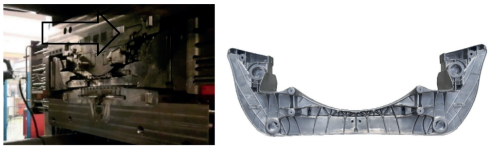
In addition, in order to guarantee their proper alignment and a constant component’s thickness proper devices have been developed and included into the die. It’s worthwhile to note that this component’s manufacturing requests a high tonnage (at least 3000 t) vacuum machine as a result of the remarkable dimensions of casting (about 1260x450 mm) and sliders (approximately equal to the piece) and the die (about double of the piece).
Afterwards, additional iterations of structural and process finite element analyses have been performed in order to obtain a final optimized design. Therefore, this sequence of steps brought to an increased lightweighting (from the initial 35% to 47%) of the suspension cross beam. Then, the dies have been manufactured and some prototypes have been casted (Fig. 3). The finite element analyses conducted during the design have been useful for the manufacturing of the dies (i.e. local cooling, squeeze, chill-vents, gate injection, etc. ) and for the definition of the initial process parameters.
After that, some castings have been analyzed through a proper X-ray machine and with a 3D scanner device in order to identify the macro-defect (porosity and deformation). The X-ray results confirmed the presence of some porosities in the thickest sections, already evaluated during FEM simulations (Fig. 4).
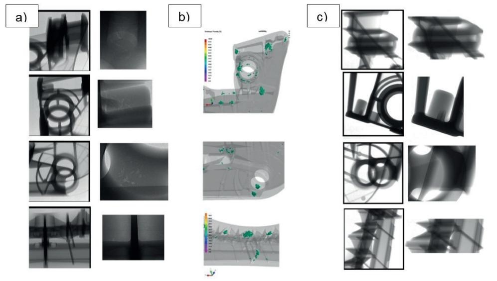
Dimensional analysis has given the following results: no relevant twist and maximum bending deformation towards the symmetry middle plane of about 1.8 mm/edge. The direction of the general deformation behavior measured are coherent with the casting simulations, while the absolute values are smaller than expected (max measured about 1.8 mm instead max simulated about of 3.8 mm) mainly because it is hard to give an a priori exact estimation of the numerous process parameters and boundary conditions, especially for the production of a so complex component. Following these considerations, some die modification have been conducted and further experimental casting activities have been performed with a careful iterative selection of the proper process parameters. It is worthwhile to note that afterwards porosities have been minimized and a correct hard points’ alignment has been reached (Fig.3). Next steps include a detailed validation and testing activity composed by test bench road simulator, tensile, mechanical and microstructural tests, salt spray test, etc.
CONCLUSION
The present paper enhances the lightweight optimization for commercial vehicles developing a technically reliable and cost effective safety component for Light Commercial Vehicles (LCVs) in aluminum alloy. In particular, a preliminary benchmark on a complete suspension assembly for LCVs has been performed, outlining the object of the study in a suspension cross beam element, usually made with metal sheet parts or steel tubes welded together in order to fulfil costs and resistance requirements. Subsequently, different lightweight suspension cross beams have been developed and materials, processes, technologies and business case have been analyzed finding the best solution in a high pressure die casting aluminum component. The shape and the technology production of the studied component have been completely devised by optimizing the mechanical properties and by reducing the material used. The design have been enhanced thanks to further iterations of structural and process finite element analyses. In detail, a proper component resistance has been achieved by the selection of a primary AlSi9MgMn alloy and by the substitution of the traditional high pressure die casting plane or “U” shape with a completely hollow structure obtained through the addition of sliders for the total length of the component. Thereafter, the manufacturing of the prototypes has been performed on a high tonnage (at least 3000 t) vacuum machine as a result of the remarkable dimensions of casting (about 1260x450 mm) and sliders (approximately equal to the piece), and the die (about double of the piece). Afterwards, some castings have been analyzed through a proper X-ray machine and with a 3D scanner device. In particular, the X-ray results confirmed the presence of some porosities in the thickest sections, already evaluated during FEM simulations. Anyway, the direction of the deformations measured is coherent with the casting simulations, while the absolute values are smaller than expected (about 1.8 mm instead of 3.8 mm). Finally, porosities have been minimized and a correct hard points’ alignment has been reached thanks to some die modification and a careful iterative selection of the proper process parameters. Next steps includes a detailed validation and testing activity composed by test bench road simulator, tensile, mechanical and microstructural tests, salt spray test, etc.
ACKNOWLEDGEMENTS
Streparava Spa is grateful to Co.Stamp Srl for the open technical cooperation during the project.
REFERENCES
[1] J. HIRSCH, Materials forum volume 28, (2004), p 15.
[2] S.DAS, JOM, 8, (2000), p.41-44.
[3] L. KALLIEN, T. WEIDLER, M. BECKER, International foundry research, 4, (2014), p. 20-27.
[4] R.MOSCHINI, R.MOLINA, XXXI Congresso tecnico di fonderia ASSOFOND, (2012).
[5] RHEINFELDEN, Leghe d’alluminio da pressocolata.