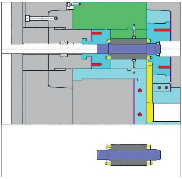
Fig. 8 – Horizontal pressure die caster with tooling for rotor
casting in closed position. The arbor (dark blue) and the steel
rotor laminations (dark gray) are shown in the insert and in
position in the machine. Copper from the shot sleeve biscuit,
runner bar and end rings is shown in yellow. The nickel alloy end
ring inserts are shown in medium blue with electrical resistance
heater elements in red. These are backed with insulation (pink)
as are the runner inserts which would be nickel alloy or tungsten.
Red circles here indicate heater positions. The moveable slide
to allow insertion and removal of the rotor is shown in green.
Ordinary steel backing plates of the master mold set are shown
in light gray. (Courtesy of DieTec, GmbH)