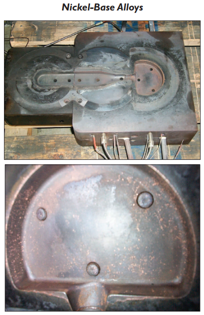
Fig. 6 – Top: Moving half TZM and Anviloy die inserts after
940 shots. TZM is in the bottom (left) position and Anviloy in
the middle and upper positions. Electrical resistance heaters
and thermocouple leads are visible on the lower edge of the
mounting plate. Bottom: Close-up of Anviloy die inserts after
500 shoots.