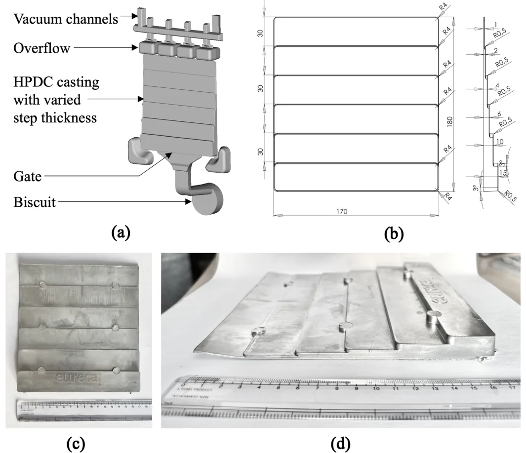
Fig. 1—(a) Diagram of HPDC configuration showing different parts, (b) Schematic diagram showing the dimensions of the die used in the HPDC process, (c) Top view of an actual cast part, and (d) Side view of an actual cast part showing the steps with different wall thicknesses.
Fig. 1—(a) Diagram of HPDC configuration showing different parts, (b) Schematic diagram showing the dimensions of the die used in the HPDC process, (c) Top view of an actual cast part, and (d) Side view of an actual cast part showing the steps with different wall thicknesses.