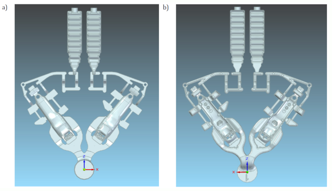
Fig. 1. Photograph of the project under analysis. View: a) from the fixed half; b) from the mobile halfFig. 2. Thermal images of the mould used in the study: a) fixed half; b) mobile halfFig. 3. The result of an input simulationa)b)a)b)
Fig. 1. Photograph of the project under analysis. View: a) from the fixed half; b) from the mobile halfFig. 2. Thermal images of the mould used in the study: a) fixed half; b) mobile halfFig. 3. The result of an input simulationa)b)a)b)